


DFG-100 AND DFG -200 SERIES
CONVECTION OVEN
INSTALLATION -- OPERATION -- MAINTENANCE
LA SÉRIE DFG-100 ET DFG-200
FOURS À CONVECTION
MANUEL D’INSTALLATION -- FONCTIONNEMENT -- ENTRETIEN
BLODGETT OVEN COMPANY
www.blodgett.com
44 Lakeside Avenue, Burlington, Vermont 05401 USA Telephone (800) 331-5842, (802) 860-3700 Fax: (802)864-0183
PN 90055 Rev U (1/03)
E 2003 --- G.S. Blodgett Corporation

IMPORTANT
WARNIN G:IMPROPER INSTALLATION, ADJUSTMENT, ALTERATION, SERVICE OR
MAINTENAN C E CAN CAUSE PROPERTY DAMAGE, INJURY OR DEATH .READ THE
INSTALLA TION, OPERATING AND MAINTENANCE INSTRUCTIONS THOROUGHLY
BEFORE INSTALLING OR SERVICING THIS EQUIPMENT
AVERTI SSEMEN T: UNE INST A L LATION, UN AJUSTEMENT, UNE ALTÉRATION, UN
SERVICE OU UN ENTRETIEN NON CONFORME AUX NORMES PEUT CAUSER DES
DOMMAGESÀ LA PROPRIÉTE,DES BLESSURES OU LA MORT. LISEZ ATTENTIVEMENT LES DIRECTIVES D’INST A L LATION, D’OPÉRATI ON ET D’ENTRETIENAV A N T
DE FAIRE L’INST A L LATION OU L’ENTRETIEN DE CET ÉQUIPEMENT.
INSTRUCTIONS TO BE FOLLOWED IN THE EVENT THE USER SMELLS GAS
MUST BE POSTED IN A PROMINENT LOCATION. THIS INFORMATION MAY BE
OBTAINED BY CONTACTING YOUR LOCAL GAS SUPPLIER.
LES INSTRUCTIONS À RESPECTER AU CAS OÙ L’UTILISATEUR PERÇOIT UNE
ODEUR DE GAZ DOIVENT ÊTRE AFFICHÉES DANS UN ENDROIT BIEN VISIBLE.
VOUS POUVEZ VOUS LES PROCURER AUPRÈS DE VOTRE FOURNISSEUR DE
GAZ LOCAL.
FORYOURSAFETY
Do not store or use gasoline or other flammable vapors or liquids in the vicinity
of this or any other appliance.
AVERTISSEMENT
Ne pas entreposer ni utiliser de l’essence ni d’autres vapeurs ou liquides inflammables dans le voisinage de cet appariel, ni de tout autre appareil.
The information contained in this manual is important for the proper installation,
use, and maintenance of this oven. Adherence to these procedures and instructions will result in satisfactory baking results and long, trouble free service.
Please read this manual carefully and retain it for future refere nce.
Les informations données dans le présent manuel sont importantes pour installer,
utiliser et entretenir correctement ce four. Le respect de ces instructio n s et procédures permettra d’obtenir de bons résultats de cuisson et une longue durée de service sans problèmes. Veuillez lire le présent manuel et le conserver pour pouvoir
vous y reporter à l’avenir.
Errors: Descriptive, typographic or pictorial errors are subject to correction. Specifica-
tions are subject to change without notice.
Erreurs:Les erreurs de description, de typographie ou d’illustration font l’objet de
corrections. Les caractéristiques sont sujettes à modifications sans préavis.

THE REPUTATION YOU CAN COUNT ON
UNE RÉPUTATION SUR LAQUELLE VOUS POUVEZ COMPTER
For over a century and a half, The Blodgett Oven Company has been building
ovens and nothing but ovens. We’ve set the industry’s quality standard for all
kinds of ovens for every foodservice operation regardless of size, application
or budget. In fact, no one offers more models, sizes, and oven applications
than Blodgett; gas and electric, full-size, half-size, countertop and deck, convection, Cook’n Hold, Combi-Ovens and the industry’s highest quality Pizza
Oven line. For more information on the full line of Blodgett ovens contact your
Blodgett representative.
Cela fait maintenant dessus un siècle et demi que Blodgett se spécialisedans
la fabrication de fours. Nous avons établi les normes de qualité qui s’appliquent dans l’industrie à tous les types de fours utilisés dans les services alimentaires, quel qu’en soit la taille, l’exploitation ou le budget. En fait, ni n’offre
plus de modèles, de tailles et d’applications de fours que Blodgett. À gaz et
électriques. De tailles différentes, sur plan de travail et superposables. Qu’il
s’agisse de fours à convection, des modèles Cook’n Hold et Combi-Oven, ou
de la gamme de fours à pizzas de la plus haute qualité offerte sur le marché.
Pour de plus amples informations sur la gamme complète de fours Blodgett,
veuillez contacter votre représentant Blodgett.

Your Service Agency’s Address:
Adressedevotreagencedeservice:
Model/Modèl:
Serial Number/Numéro de série:
Your oven was installed by/
Installateur de votre four:
Your oven’s installation was checked by/
Contrôleur de l’installation de votre four:

Table of Contents/Table des Matières
Introduction
Oven Description and Specifications 2....
Oven Components 3....................
Installation
Delivery and Location 4.................
Oven Assembly 5......................
NSF Bolts 5..........................
Leg Attachment 6.....................
Caster Assembly 6....................
Double Section Assembly 7............
Oven Leveling 7......................
Ventilation 8...........................
Canopy Type Exhaust Hood 8..........
Direct Flue Arrangement 9.............
Utility Connections ---
Standards and Codes 10.................
Gas Connection 11......................
Electrical Connection 14.................
Initial Startup 15.........................
Operation
Safety Information 16....................
CH-Pro3 (Solid State Programmable
Digital Control) 17.......................
Solid State Digital Control 20..............
Solid State Manual Control 22.............
Blodgett IQ2T Control 23................
Cook and Hold Control 32................
Pulse Plus 34...........................
Humidaire 35...........................
Intelliplus with Chain Event Control 36.....
Intellitouch II Control 39..................
How Cook and Hold Works 42............
General Guidelines for Operating
Personnel 43............................
Suggested Times and Temperatures 44....
Maintenance
Cleaning and Preventative Maintenance 45.
Troubleshooting Guide 46................
Introduction
Description et Spécifications du Four 48....
Éléments du Four 49.....................
Installation
Livraison et Implantation 50...............
Montage du Four 51.....................
Boulons NSF 51.......................
Assemblage des Pieds 52...............
Montage des Roulettes 52..............
Montage de la Section Double 53........
MiseàNiveauduFour 53...............
Ventilation 54...........................
Hotte D’évacuation Type Voûte 54.......
En Prise Directe 55.....................
Branchements de Service --- Normes et
Codes 56...............................
Branchement de Gaz 57.................
Raccordement Électrique 60..............
Mise en Marche Initiale 61................
Utilisation
Informations de Sécurité 62...............
CH-Pro3 (Commande Numérique Program-
mable pour Semi-Conducteurs) 63........
Commandes Numériques à
Semi-Conducteurs 67....................
Commandes à Semi -Conducteurs 70......
Contrôle du Blodgett IQ2T 71............
Commande Cuisson et Maintien 81........
Pulse Plus 83...........................
Humidaire 84...........................
Intelliplus avec Commandes à
Enchaînement 85........................
Intellitouch II 88.........................
Principe de la Fonction de Cuisson et
Maintien 91.............................
Consignes Générales à l’Intention des
Utilasateurs 92..........................
Durées et Températures Suggérées 93.....
Entretien
Nettoyage et Entretien Préventif 94........
GuidedeDétectiondesPannes 95........

Introduction
Oven Description and Specifications
Cooking in a convection oven differs from cooking
in a conventionaldeck or range oven since heated
air is constantly recirculated over the product by
a fan in an enclosed chamber. The moving air continually strips away the layer of cool air surrounding the product, quickly allowing the heat to penetrate. The result is a high quality product, cooked
at a lower temperature in a shorter amount of time.
Blodgettconvection ovens represent the latest advancement in energy efficiency, reliability, and
ease of operation. Heat normally lost, is recircu lated within the cooking chamber before being
vented from the oven: resulting in substantial reductions in energy consumption and enhanced
oven performance.
Air Flow Pattern for Blodgett DFG Convection Ovens
Figure 1
GAS SPECIFICATIONS -- U.S., Cana da and General Export
Natural Gas Propane Gas
US Units SI Units US Units SI Units
Heating Value 1000 BTU/cu.ft. 37.3 MJ/m
Specific Gravity (air=1.0) 0.63 0.63 1.53 1.53
Oven Input
DFG-100-3
DFG-200-L
Main Burner Orifice Size
DFG-100-3
DFG-200-L
GAS SPECIFICATIONS -- DFG-100-3 for Australia
Oven Input --- 58 MJ/h --- 58 MJ/h
Main Burner Orifice Size 38 MTD* 2.58 mm 1/16” dia. 1.6 mm
NOTE: * --- Multiple Twist Drill
55,000 BTU/hr
60,000 BTU/hr
38 MTD*
36 MTD*
16.2 kW
17.6 kW
2.6 mm
2.7 mm
3
2550 BTU/cu. ft. 95.0 MJ/m
55,000 BTU/hr
60,000 BTU/hr
1/16” dia.
52 MTD*
16.2 kW
17.6 kW
1.6 mm
1.6 mm
3
2
Introduction
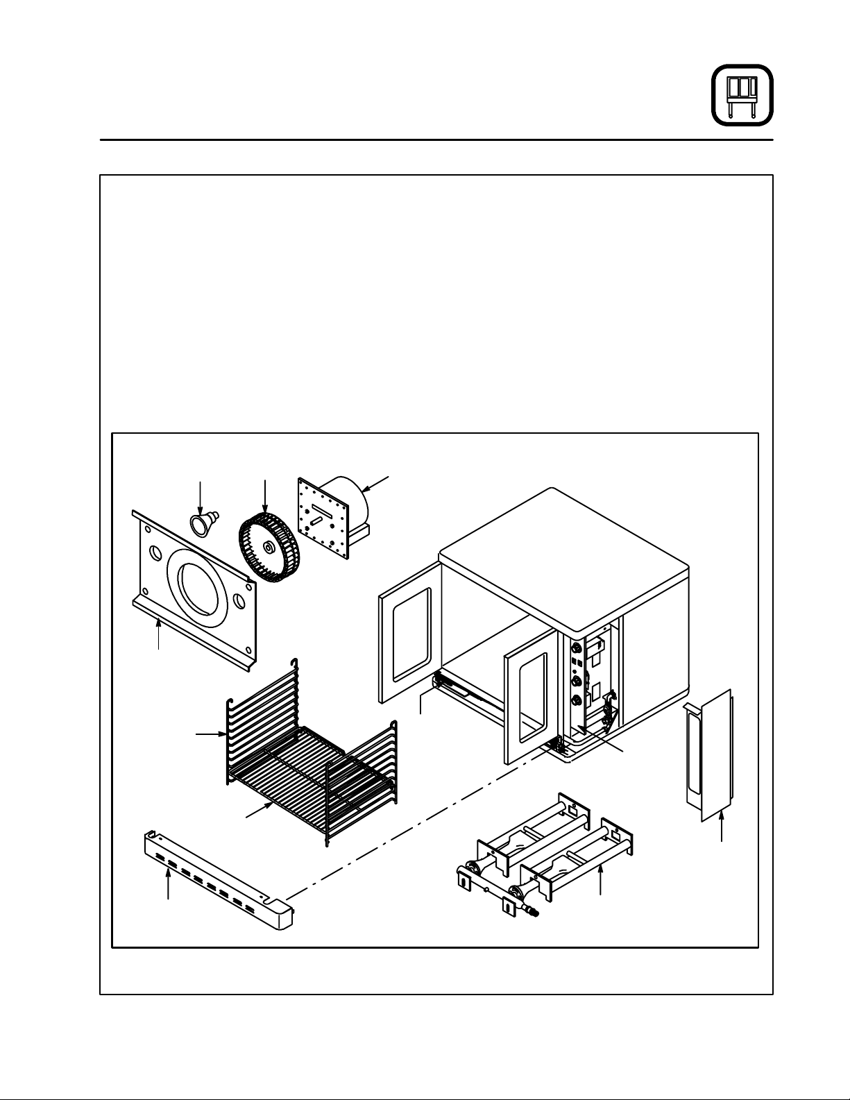
Oven Components
Combustion Cover --- provides access to the
combustion compartment on gas ovens.
Combustion Compartment --- contains combus-
tion burners on gas ovens.
Combustion Burners --- provide heat to the bak-
ing chamber on gas ovens.
Chain & Turnbuckle --- controls operation of the
oven doors.
Control Panel --- contains wiring and components
to control the oven operation.
Oven Racks --- five racks are provided standard.
Additional racks are available.
Oven
Lights
Blower
Wheel
Convection
Motor
Rack Supports --- h o l d ov e n r a c k s .
Blower Wheel Cover --- locatedon the back interi-
or wall of the oven. Protects the blower wheel.
Blower Wheel --- spins to circulate hot air in the
baking chamber.
Convection Motor --- provides power to turn the
blower w h eel.
Oven Lights --- provide lighting inside the baking
compartment.
Blower
Wheel Cover
Rack Support
Combustion
Cover
Chain &
Turn b u c kle
Control
Panel
Oven Rack
Control
Panel Cover
Combustion
Burners
Figure 2
3

Installation
Delivery and Location
DELIVERY AND INSPECTION
All Blodgett ovens are shipped in containers to
prevent damage. Upon delivery of your new oven:
D
Inspect the shipping container for external damage. Any evidence of damage should be noted
on the delivery receipt which must be signed by
the driver.
D
Uncrate the oven and check for internal damage. Carriers will accept claims for concealed
damage if notified within fifteen days of delivery
and the shipping container is retained for inspection.
The Blodgett Oven Company cannot assume
responsibility for loss or damage suffered in
transit. The carrier assumed full responsibility
for delivery in good order when the shipment
was accepted. We are, however, prepared to
assist you if filing a claim is necessary.
OVEN LOCATION
The well planned and proper placement of your
oven will result in long term operator convenience
and satisfactory performance.
The following clearances must be maintained between the oven and any combustible or non-combustible construction.
DFG100
D
Oven body right side --- 2” (5cm)
D
Oven body left side --- 2” (5cm)
D
Oven body back --- 0” (0cm)
D
Oven body bottom --- 6” (15cm)
DFG200
D
Oven body right side --- 6” (15cm)
D
Oven body left side --- 6” 6” (15cm)
D
Oven body back --- 6” (15cm)
D
Oven body bottom --- 6” (15cm)
The following clearances must be available for servicing.
D
Oven body sides --- 12” (30cm)
D
Oven body back --- 12” (30cm)
NOTE: On gas models, routine servicingcan usu-
ally be accomplished within the limited
movement provided by the gas hose restraint. If the oven needs to be moved further from the wall, the gas must first be
turned off and disconnected from the oven
before removing the restraint. Reconnect
the restraint after the oven has been returned to its normal position.
It is essential that an adequate air supply to the
oven be maintained to provide a sufficient flow of
combustion and ventilation air.
D
Place the oven in an area that is free of drafts.
D
Keepthe oven area free and clear of all combustiblessuch as paper, cardboard, and flammable
liquids and solvents.
D
NSF requires 6” of clearance on the bottom a nd
sides of the unit for cleaning. Do not place the
oven on a curb base or seal to a wall.
D
The location must provide adequate clearance
for the air opening into the combustion chamber.
Before making any utility connections to this oven,
check the rating plate to be sure the oven specifications are compatible with the gas and electrical
services supplied for the oven.
1. Remove the combustion compartment cover.
The rating plate is attached to the frame on the
left side of the combustion compartment.
4
Installation
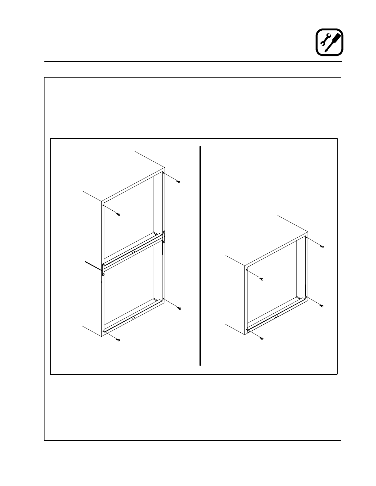
Oven Assembly
NSF BOLTS
These bolts are required by NSF to block any exposed hole on the back of an oven. This includes:
D
any unit, single or stacked, without a back panel.
D
any holes in stacked units not used for mounting stacking brackets.
1. Locate the 5/16” bolts that were shipped with
the oven.
2. InstalltheboltsasshowninFigure3.
Double Stacked Units Units without Back Panels
Figure 3
5
Installation
Oven Assembly
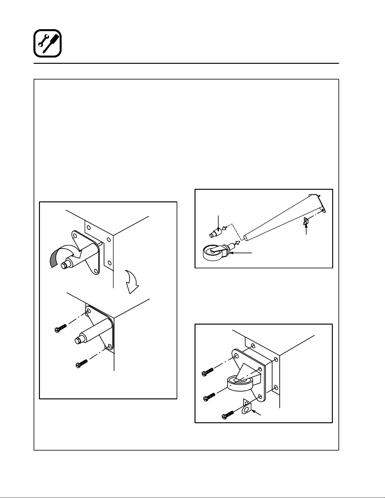
LEG ATTACHMENT
1. Push the oven onto a lift with the bottom of the
oven down.
2. Align the threaded stud in each leg with the
nut located inside each bottom corner of the
oven frame. Turn the legs clockwise and tighten to the nearest full turn.
3. Align the two leg plate holes in each leg with
those in the oven bottom. Secure each leg using two 1/2” bolts.
NOTE: If using casters see CASTER AS-
SEMBLY before proceeding.
4. Level the oven by screwing the adjustable leg
feet in or out as necessary.
CASTER ASSEMBLY
NOTE: Install the locking casters on the front of
the oven. Install the non-locking casters on
the back of the oven.
NOTE: Use a gas hose restraint on all units with
casters. See page 13.
Casters for Singl e and Double Stacked Ovens:
1. Attach the legs as described.
2. Pry the adjustable feet out of the legs.
3. Insert one caster into each leg as shown.
Tighten the lock nuts to secure the casters.
Adjustable
Leg Foot
Gas Hose
Restraint Bracket
Caster Assembly
Figure 5
6” (15 cm) Legs Shown
Figure 4
Low Profile Castersfor Double StackedOvens:
1. Align the three holes in each caster assembly
plate with those in the oven bottom. Secure
each caster using three 1/2” bolts.
Gas Hose Restraint Bracket
Figure 6
6
Installation
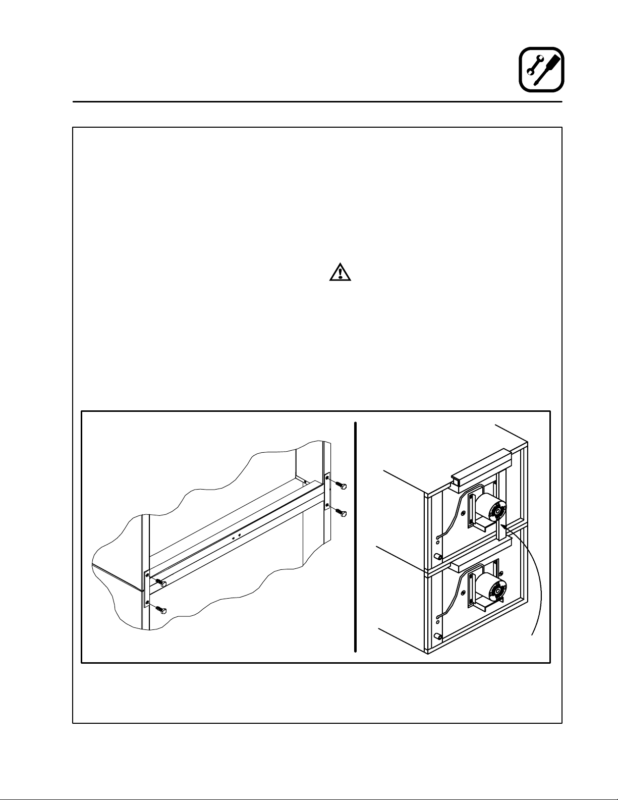
Oven Assembly
DOUBLE SECTION ASSEMBLY
NOTE: Old style ovens refer to units with painted ex-
posed rear angle. New style ovens refer to
units with rear angle iron enclosed in steel.
The following instructions apply to stacking two
new style ovens.
1. Secure the short legs to the bottom sections
as described.
2. Place the upper section in position on top of
the lower oven.
3. Attach the stacking brackets using the remaining 5/16” bolts shipped with the ovens.
4. Attach the flue connector.
The following instructions apply to stacking a new
styleovenonanoldstyleoven.
1. Secure the short legs to the bottom sections
as described.
2. Place the upper section in position on top of
the lower oven.
3. Attach the stacking brackets using the remaining 5/16” bolts shipped with the ovens.
4. Drill a clearance hole for a 5/16” bolt in the
angle iron of the old style oven. Use the holes
in the stacking brackets as a pilot.
5. Attach the stacking brackets to the old style
oven with the 5/16” bolts and nuts provided in
the kit.
6. Attach the flue connector.
WARNING!!
Whenstackingovensbesuretoremove
thesingleovenflueboxespriortoattaching three-piece connector.
OVEN LEVELING
After assembly, the oven should be leveled and
moved to the operating location.
1. The oven can be leveled by adjusting the feet
or casters located on the bottom of each leg.
Figure 7
7
Flue
Connector
Installation
Ventilation
On gas models the installation of a proper ventilation system cannot be over emphasized. This system removes unwanted vapors and products of
combustion from the operating area.
This oven may be vented using either:
D
A mechanically driven, canopy type, exhaust
hood, or
D
A direct flue arrangement.
U.S. and Canadian installations
Refer to your local ventilation codes. In the absence of local codes, refer to the National ventilation code titled, “Standard for the Installation of
Equipment for the Removal of Smoke and Grease
Laden Vapors from Commercial Cooking Equipment”, NFPA-96-Latest Edition.
Australia and general export installations
Installation must conform with Local and National
installation standards. Local installation codes
and/or requirements may vary. If you have any
questions regarding the proper installationand/or
operation of your Blodgett oven, please contact
your local distributor. If you do not have a local distributor, please callthe Blodgett Oven Companyat
0011-802-860-3700.
CANOPY TYPE EXHAUST HOOD
A mechanically driven, canopy type exhaust hood
is the preferred method of ventilation.
The hood should be sized to completely cover the
equipment plus an overhang of at least 6” (15 cm)
on all sides not adjacent to a wall. The distance
from the floor to the lower edge of the hood should
not exceed 7’ (2.1m).
The total makeup and exhaust air requirements for
hood capacity should be approximately 30 CFM
3
(.85 m
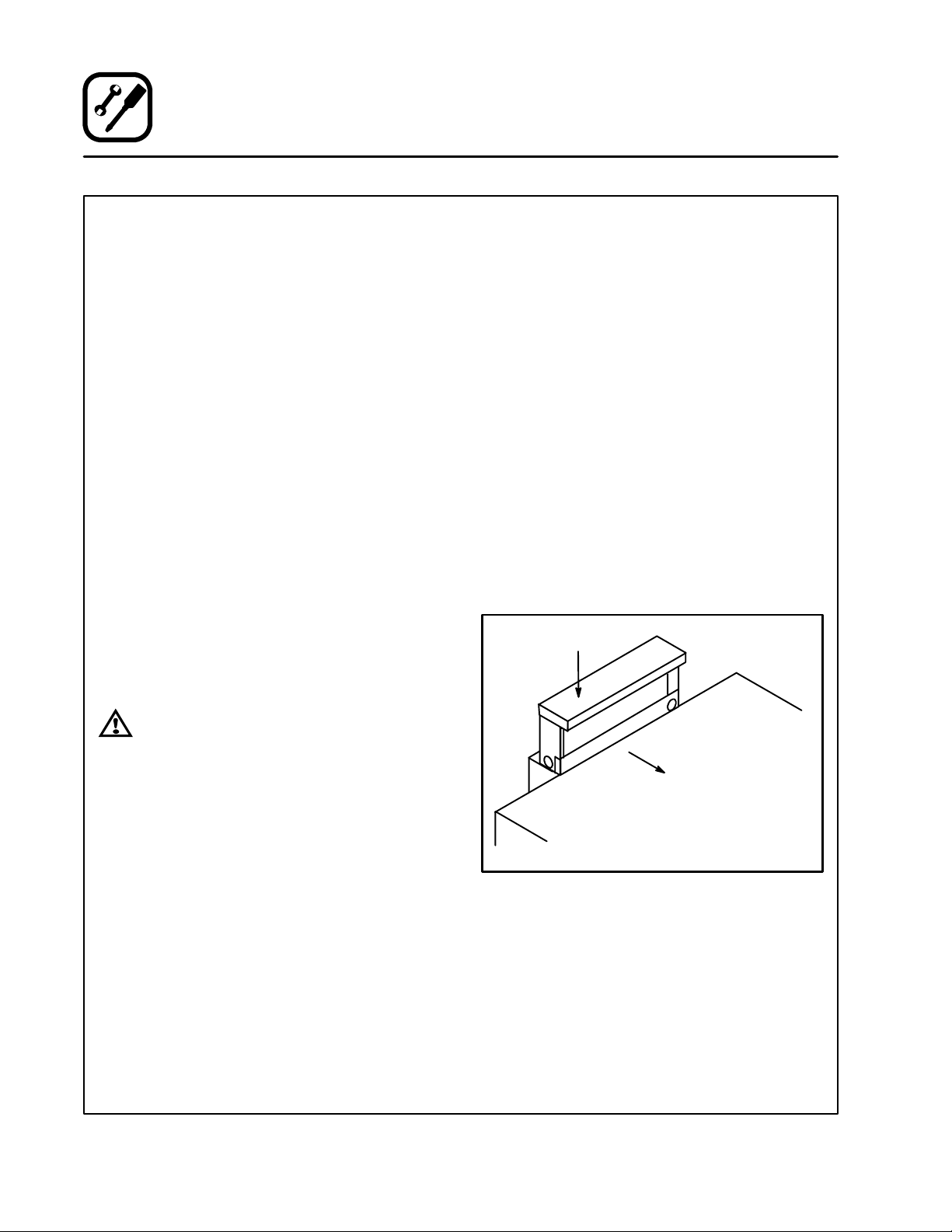
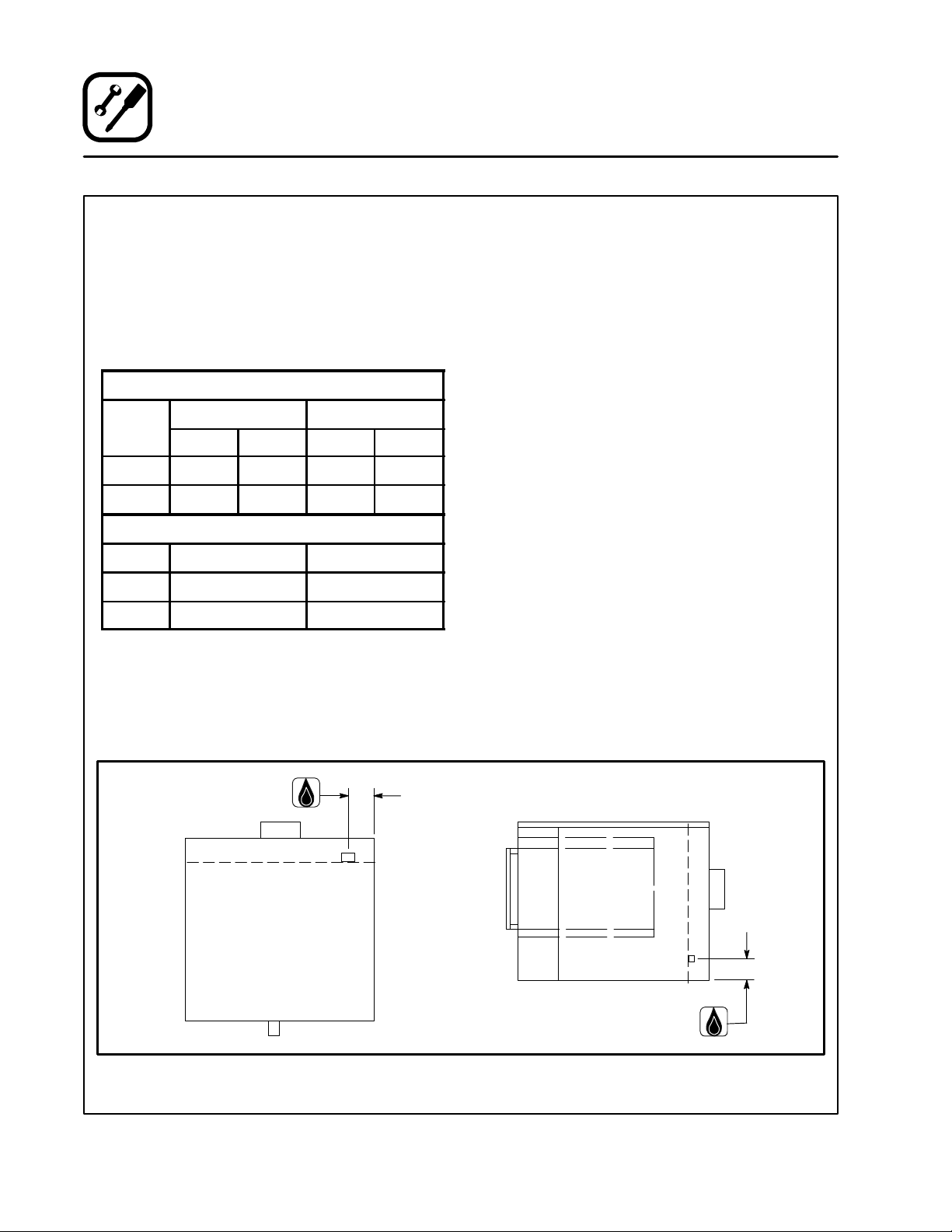
Installing the canopy hood draft diverter
Ovens ordered for hood venting are supplied with
a draft diverter. Install the draft diverter as follows:
1. Place the diverter over the flue connector with
2. Secure both ends with the sheet metal screw s
) for each oven section.
the open area facing the front of the oven. See
Figure 8.
provided.
Draft Diverter
WARNING:
Failure to properly vent the oven can be
hazardous to the health of the operator
and may result in operational problems,
unsatisfactory baking and possible damage to the equipment.
Damage sustained as a direct result of improper ventilation will not be covered by
the manufacturer’s warranty.
Front of
Oven
Figure 8
8
Installation
Ventilation
DIRECT FLUE ARRANGEMENT
When the installation of a mechanically driven exhaust hood is impractical the oven may be vented
by a direct flue arrangement.
WARNING!!
It is essential that the direct flue be
installed as follows. Incorrect installation
will result in unsatisfactory baking and
oven damage.
ThefluemustbeclassBorbetter.Theheightof
theflueshouldrise6-8ft(2-2.5m)abovetheroof
of the building or any proximate structure. Never
direct vent the oven into a hood. The flue should
be capped with a UL Listedtype vent cap to isolate
the unit from external environmental conditions.
Thedirectventcannotreplaceairconsumedand
vented by the oven. Provisions must be made to
supply the room with sufficient make-up air. Total
make-up a ir requirements for each oven section
should be approximately 30 CFM (.85 m
tion. To increase t he supply air entering the room,
a ventilation expert should be consulted.
3
)persec-
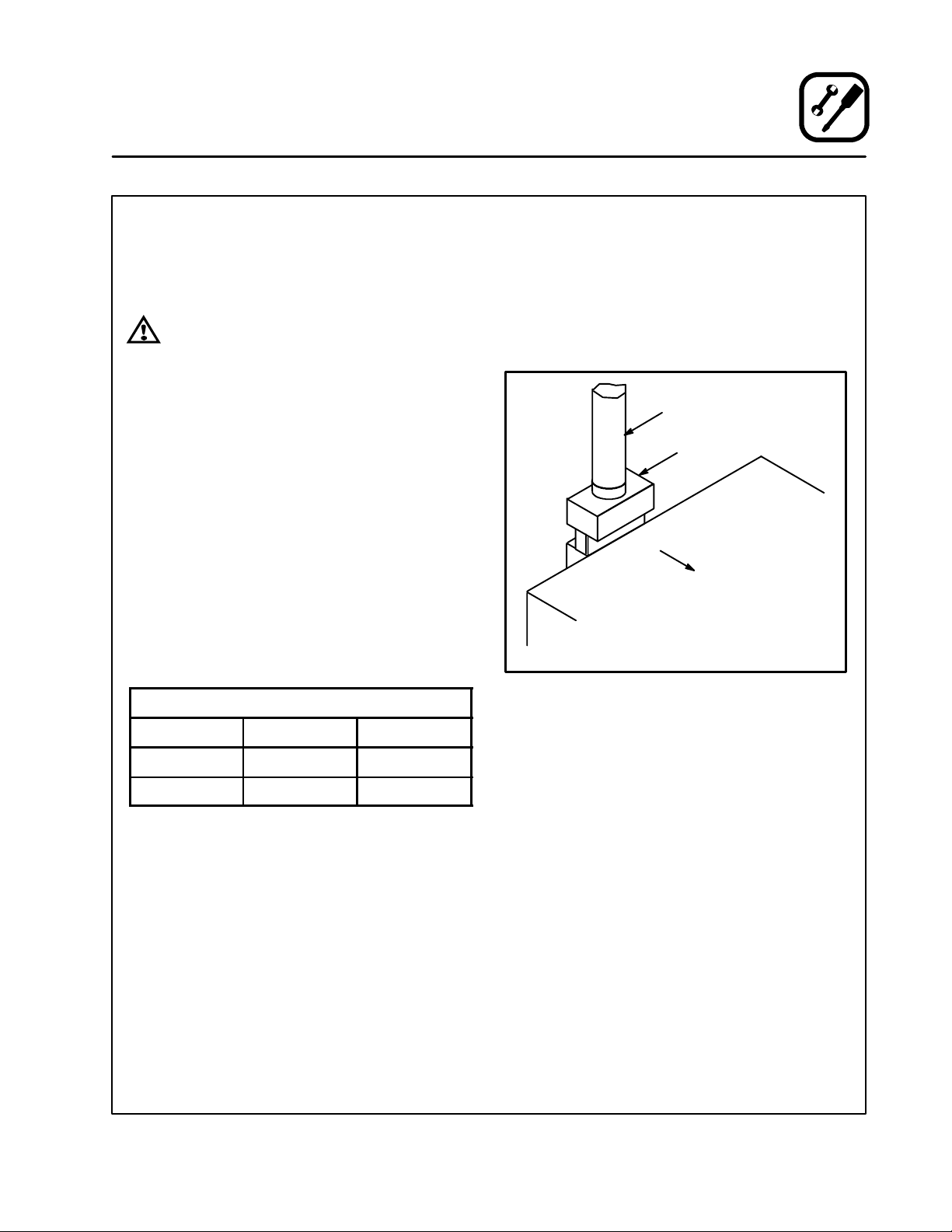
Installing the draft hood
Ovens ordered for direct venting are supplied with
a draft hood. Install the draft hood as follows:
1. Place the draft hood over the flue connector .
SeeFigure9.
2. Secure both ends with the sheet metal screw s
provided.
Flue
Draft Hood
Front of
Oven
FLUE DIAMETER
Oven Single Double
DFG-100 6” (15cm) 6” (15cm)
DFG-200 6” (15cm) 8” (20cm)
Figure 9
9
Installation
Utility Connections --- Standards and Codes
THE INSTALLATION INSTRUCTIONS CONTAINED HEREIN ARE FOR THE USE OF QUALIFIED INSTALLATIONAND SERVICE PERSONNEL
ONLY. INSTALLATION OR SERVICE BY OTHER
THAN QUALIFIED PERSONNEL MAY RESULT IN
DAMAGE TO THE OVEN AND/OR I NJURY TO
THE OPERATOR.
Qualified installation personnel are individuals, a
firm, a corporation, or a company which either in
person or through a representative are engaged
in, and responsible for:
D
the installation or replacement of gas piping
and the connection, installation, repair or s ervicing of equipment.
D
the installation of electrical wiring from the electric meter, main control box or service outlet to
the electric appliance.
Qualified installation personnel must be experienced in such work, familiar with all precautions
required, and have complied with all requirements
of state or local authorities having jurisdiction.
U.S. and Canadian installations
Installation must conform with local codes, or in
the absence of local codes, with the National Fuel
Gas Code, NFPA54/ANSI Z223.1 ---Latest Edition,
the Natural Gas Installation Code CAN/CGAB149.1 or the Propane Installation Code, CAN/
CGA-B149.2 as applicable.
Installation must conform with local codes, or in
the absence of local codes, with the National Elec-
trical Code, ANSI/NFPA 70---Latest Edition and/or
CanadianNationalElectric Code C22.2 as applica-
ble.
Australia and general export installations
Installation must conform with Local and National
installation standards. Local installation codes
and/or requirements may vary. If you have any
questions regarding the proper installationand/or
operation of your Blodgett oven, please contact
your local distributor. If you do not have a local distributor, please callthe Blodgett Oven Companyat
0011-802-860-3700.
10
Installation
p
p
g
Gas Connection
GAS PIPING
A properly sized gas supply system is essential for
maximum oven performance. Piping should be
sized to provide a supply of gas sufficient to meet
the maximum demand of all appliances on the line
without loss of pressure at the equipment.
Example:
NOTE: BTU values in the following example are
for natural gas.
You purchase a DFG-100 convection oven to add
to your existing cook line.
1. Add the BTU rating of yourcurrentappliances.
Pitco Fryer 120,000 BTU
6 Burner Range 60,000 BTU
Deck Oven 50,000 BTU
Total 230,000 BTU
2. Add the BTU rating of the new oven to the total.
Previous Total 230,000 BTU
DFG-100 55,000 BTU
New Total 285,000 BTU
3. Measure the distance from the gas meter to
the cook line. This is the pipe length. Let’s say
the pipe length is 40’ (12.2 m) and the pipe
size is 1” (2.54 cm).
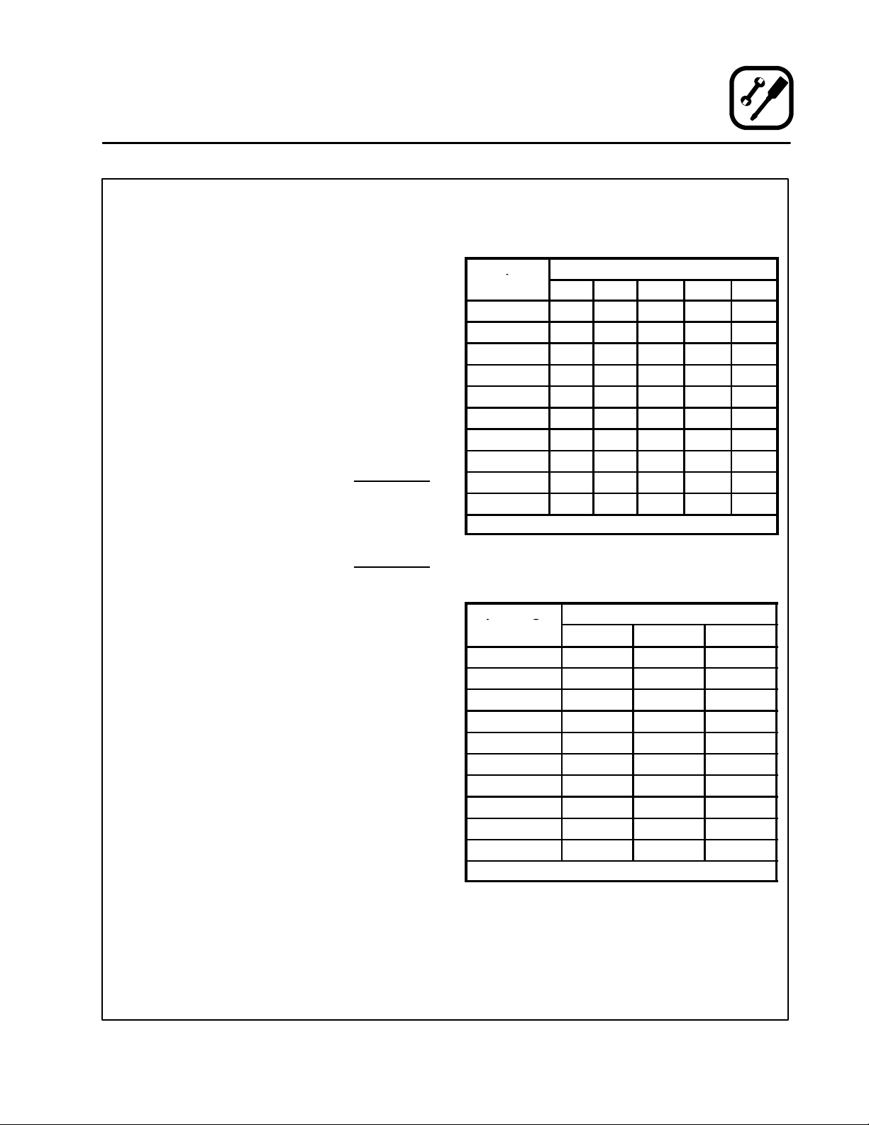
4. Use the appropriate table to determine the total capacity of your current gas piping.
The total capacity for this example is 320,000
BTU. Since the total required gas pressure,
285,000 BTU is less than 320,000 BTU, the
current gas piping will not have to be increased.
NOTE: The BTU capacities given in the tables are
for straight pipe lengths only. Any elbows
or other fittings will decrease pipe capacities. Contact your local gas supplier if you
have any questions.
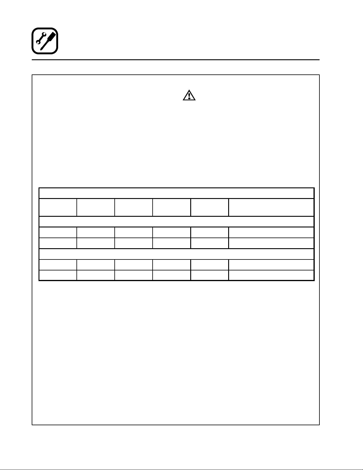
Maximum Capacity of Iron Pipe in Cubic Feet
of Natural Gas Per Hour
(Pressure drop of 0.5 Inch W.C.)
Pipe
Length (ft)
10 360 680 1400 2100 3950
20 250 465 950 1460 2750
30 200 375 770 1180 2200
40 170 320 660 990 1900
50 151 285 580 900 1680
60 138 260 530 810 1520
70 125 240 490 750 1400
80 118 220 460 690 1300
90 110 205 430 650 1220
100 103 195 400 620 1150
From the National Fuel Gas Code Part 10 Table 10-2
Maximum Capacity of Pipe in Thousands of
BTU/hr of Undiluted L.P. Gas at 11” W.C.
(Pressure drop of 0.5 Inch W.C.)
Pipe Length
(ft)
10 608 1146 3525
20 418 788 2423
30 336 632 1946
40 287 541 1665
50 255 480 1476
60 231 435 1337
70 215 404 1241
80 198 372 1144
90 187 351 1079
100 175 330 1014
From the National Fuel Gas Code Part 10 Ta ble 10-15
Nominal Size, Inches
3/4” 1” 1-1/4” 1-1/2” 2”
Outside Diameter, Inches
3/4” 1” 1-1/2”
11
Installation
Gas Connection
PRESSURE REGULATION AND TESTING
DFG-100-3 ovens are rated at 55,000 BTU/Hr.
(16.2 kW) (58 MJ) per section. DFG-200-L ovens
are rated at 60,000 BTU/Hr. (17.6 kW) (63 MJ) per
section. Each oven has been adjusted at the factory to operate with the type of gas specified on the
rating plate.
Inlet Pressure
Natural Propane
Min Max Min Max
W.C. 7.0 10.5 11.0 13.0
kPa 1.742 2.61 2.74 3.23
Manifold Pressure
Natural Propane
W.C. 3.5 10.0
kPa .87 2.49
D
Inlet Pressure --- the pressure of the gas before
it reaches the oven.
D
Manifold Pressure --- the pressure of the gas
as it enters the main burner(s).
D
Min --- the minimum pressure recommended to
operate the oven.
D
Max --- the maximum pressure at which the
manufacturer warrants the oven’s operation.
Each oven is supplied with a regulator to maintain
the proper gas pressure. The regulator is essen-
tial to the proper operation of the oven and
shouldnot be removed. It is preset to provide the
oven with 3.5” W.C. (0.87 kPa) for natural gas and
10.0” W.C. (2.50 kPa) for Propane at the manifold.
DO NOT INSTALL AN ADDITIONAL REGULATOR
WHERE THE OVEN CONNECTS TO THE GAS
SUPPLY UNLESS THE INLET PRESSURE IS
ABOVE MAXIMUM.
Prior to connecting the oven, gas lines should be
thoroughly purged of all metal filings, shavings,
pipe dope, and other debris. After connection, the
oven should be checked for correct gas pressure.
The oven and its individual shutoff valve must be
disconnected from the gas supply piping system
during any pressure testing of that system at test
pressures in excess of 1/2 psig (13.85” W.C., 3.45
kPa).
The oven must be isolated from the gas supply
piping system by closing its individual manual
shutoff valve during any pressure testing of the
gas piping system at test pressures equal or less
than 1/2 psig (13.85” W.C., 3.45 kPa).
Gas Connection 2.5” (64 mm)
Gas Connection 3.75” (85.7 mm)
Figure 10
12
GAS HOSE RESTRAINT
If the oven is mounted on casters, a commercial
flexible connector with a minimum of 3/4” (1.9 cm)
inside diameter must be used along with a quick
connect device.
The restraint, supplied with the oven, must be
used to limit the movement of the unit so that no
strain is placed upon the flexible connector . With
the restraint fully stretched the connector should
be easy to install a nd quick connect.
The restraint (ie: heavy gauge cable) should be
1,000 lb. (453 kg) test load andshould be attached
without damaging the building. DO NOT use the
gas piping or electrical conduit for the attachment
of the permanent end of the restraint! Use anchor
bolts in concrete or cement block. On wooden
walls, drive hi test wood lag screws into the studs
of the wall.
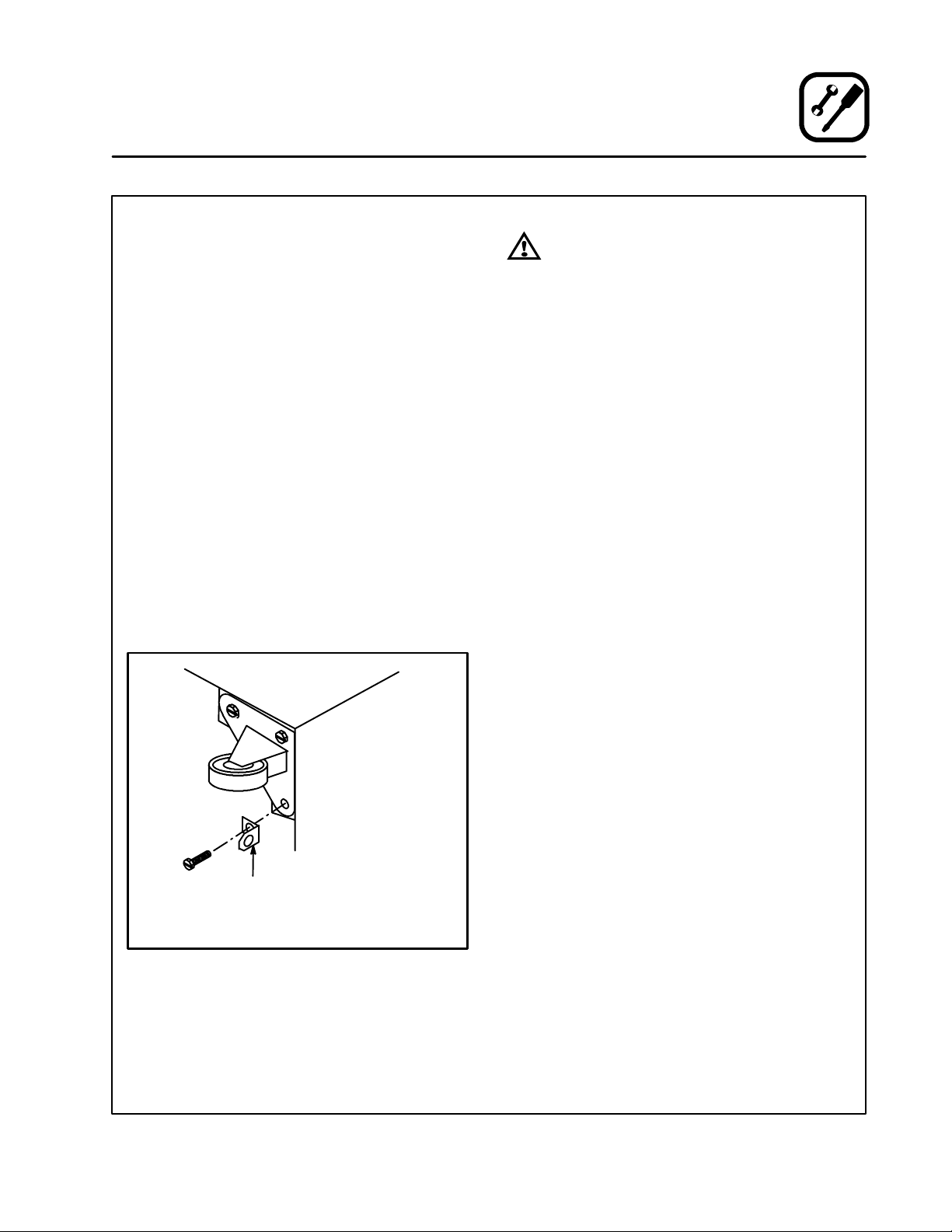
1. Mount the supplied bracket to the leg bolt just
below the gas inlet. See Figure 11.
2. Attach the clip on restraining cable to the
mounting bracket.
Installation
Gas Connection
WARNING!!
If the restraint is disconnected for any
reason it must be reconnected when the
oven is returned to its original position.
U.S. and Canadian installations
The connector must comply with the Standard for
Connectors for Movable Gas Appliances, ANSI
Z21.69 or Connectors For Moveable Gas Appliances CAN/CGA-6.16 and a quick disconnect
device that complies with the Standard for QuickDisconnect Devices for Use With Gas Fuel, ANSI
Z21.41 or Quick Disconnect For Use With Gas Fuel
CAN 1-6.9. Adequate means must be provided to
limit the movement of the appliance without depending on the connection and the quick disconnect device or its associated piping.
Australie and general export installations
The restraint and quick connect must conform
with Local and National installation standards. Local installation codes and/or requirements may
vary. If you have any questions regarding the proper installation and/or operation of your Blodgett
oven, please contact your local distributor . If you
do not have a local distributor, please call the
Blodgett Oven Company at 0011-802-860-3700.
Back of Oven
Restraint Cable
Bracket
Double stacked unit shown. Use the same procedure for
single units.
Figure 11
13
Installation
Electrical Connection
Wiring diagrams are located in the control
compartment and on the back of the oven.
This oven is supplied for connection to 115 volt
grounded circuits. The electric motor, indicator
lights and related switches are connected through
the 6’ electric supply cord found at the rear of the
oven.
ELECTRICAL SPECIFICATIONS
Model Hz Volts Phase Amps Electrical Connection
U.S. and Canadian Installations
WARNING!!
This appliance is equipped with three
pronggroundingtypeplugforyour
protection against shock hazard and
shouldbe plugged directlyintoa properly
grounded three prong receptacle. DO
NOT cut or remove the grounding prong
from this plug.
THE BLODGETT OVEN COMPANY CANNOT ASSUME RESPONSIBILITY FOR LOSS OR DAMAGE
SUFFERED AS A RESULT OF IMPROPER INSTALLATION.
(minimum size)
DFG-100-3 60 115 1 6 Cord set provided
DFG-200-L 60 115 1 6 Cord set provided
Australia and General Export Installations
DFG-100-3 50 220-240 1 3 Size per local code
DFG-200-L 50 220-240 1 3 Size per local code
14

Installation
Initial S tartup
The following is a check-list to be completed by
qualified personnel prior to turning on the
applianceforthefirsttime.
j
Open the manual shut-off valve at the rear of
the oven.
j
Remove the control panel and combustion
covers.
j
Turn the combination valve’s manual shut-off
to the on position.
j
Turn the selector switch to Cook, and the thermostat to 500_F (260_C).
The oven main burner lights, and the Oven Ready
Light comes on. With the main burner on, check
the following.
j
Verify there are no gas leaks, by checking all
gas connections w ith a soapy water solution.
j
Verify that the inlet pressure is correct. The inlet pressure can be checked at the pressure
tap located on the combination valve’s inlet
side.
j
Verify that the manifold pressure is correct.
The manifold pressure can be checked at the
pressure tap located on the manifold.
j
If the above pressure readings are set to the
recommended pressure requirements, allow
the oven to burn-off for 2 hours. If the pressure
readings are not set correctly, turn off the oven
and readjust accordingly.
ADJUSTMENTS ASSOCIATED WITH INITIAL
INSTALLATION
Each oven, and its component parts, have been
thoroughly tested and inspected prior to shipment. However, it is often necessary to further
test or adjust the oven as part of a normal and
proper installation. These adjustments are the
responsibility of the installer, or dealer. Since
these adjustments are not considered defects
in material or workmanship, they are not covered by the Original Equipment Warranty. They
include, but are not limited to:
DDDD
calibration of the thermostat
DDDD
adjustment of the doors
DDDD
burner adjustments
DDDD
leveling
DDDD
testing of gas pressure
DDDD
tightening of fasteners.
No installation should be considered complete
without proper inspection, and if necessary,
adjustment by qualified installation or service
personnel.
WARNING
The break in procedure burns off excess
oils present in the metals during fabrication. Smoke may be produced. Proper
ventilation is required.
15

Operation
Safety Information
THE INFORMATION CONTAINED IN THIS SECTION IS PROVIDED FOR THE USE OF QUALIFIED
OPERATING PERSONNEL. QUALIFIED OPERATING PERSONNEL ARE THOSE WHO HAVE
CAREFULLY READ THE INFORMATION CONTAINED IN THIS MANUAL, ARE FAMILIAR WITH
THE FUNCTIONS OF THE OVEN AND/OR HAVE
HAD PREVIOUS EXPERIENCE WITH THE OPERATIONOF THE EQUIPMENT DESCRIBED. ADHERENCE TO THE PROCEDURES RECOMMENDED HEREIN WILL ASSURE THE
ACHIEVEMENT OF OPTIMUM PERFORMANCE
AND LONG, TROUBLE-FREE SERVICE.
Please take the time to read the following safety
and operating instructions. They are the key to the
successful operation of your Blodgett conveyor
oven.
SAFETY TIPS
For your safety read before operating
What to do if you smell gas:
D
DO NOT try to light any appliance.
D
DO NOT touch any electrical switches.
D
Use an exterior phone to call your gas supplier
immediately.
D
If you cannot reach your gas supplier, call the
fire department.
What to do in the event of a power failure:
D
Turn a ll sw itch es t o off.
D
DO NOT attempt to operate the oven until the
power is restored.
NOTE: In the event of a shut-down of any kind, al-
low a five (5) minute shut off period before
attempting to restart the oven.
General safety tips:
D
DO NOT use tools to turn off the gas control. If
the gas cannot be turned off manually do not try
to repair it. Call a qualified service technician.
D
If the oven needs to be moved for a ny reason,
the gas must be turned off and disconnected
from the unit before removing the restraint
cable. Reconnect the restraint after the oven
has been returned to its original location.
D
DO NOT remove the control panel cover unless
the oven is unplugged.
16
11
13
14
Operation
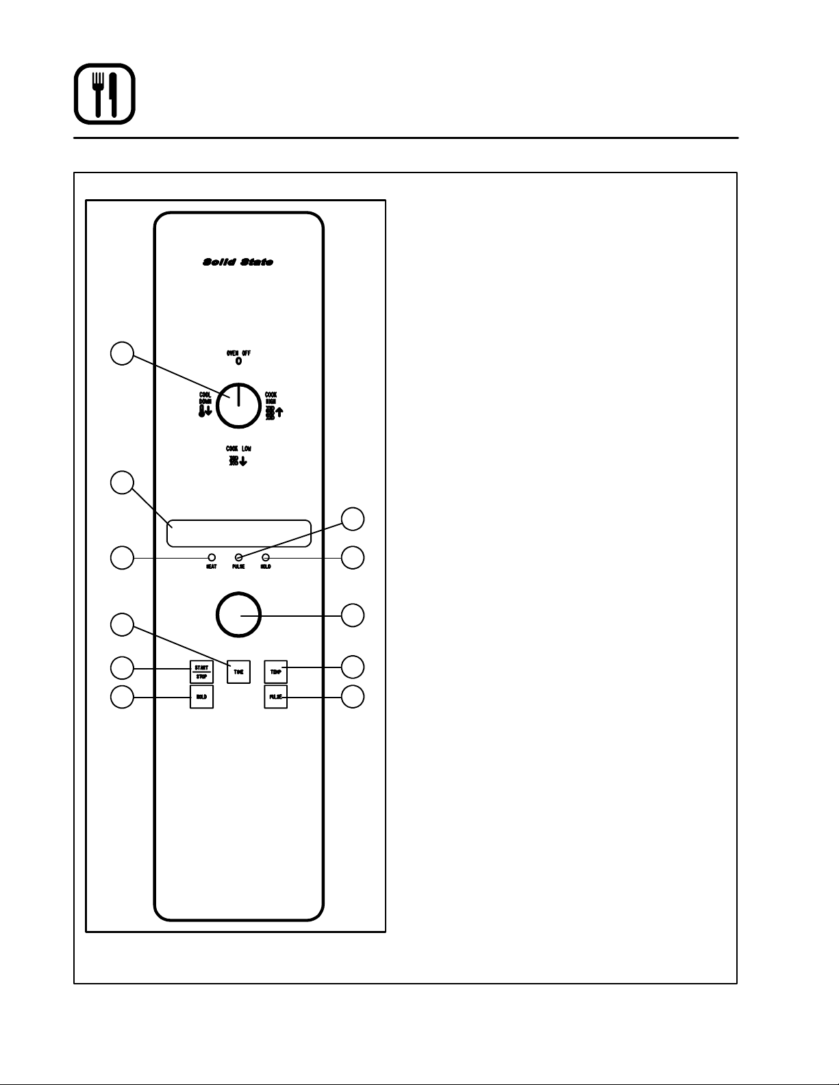
CH-Pro3 (Solid State Programmable Digital Control)
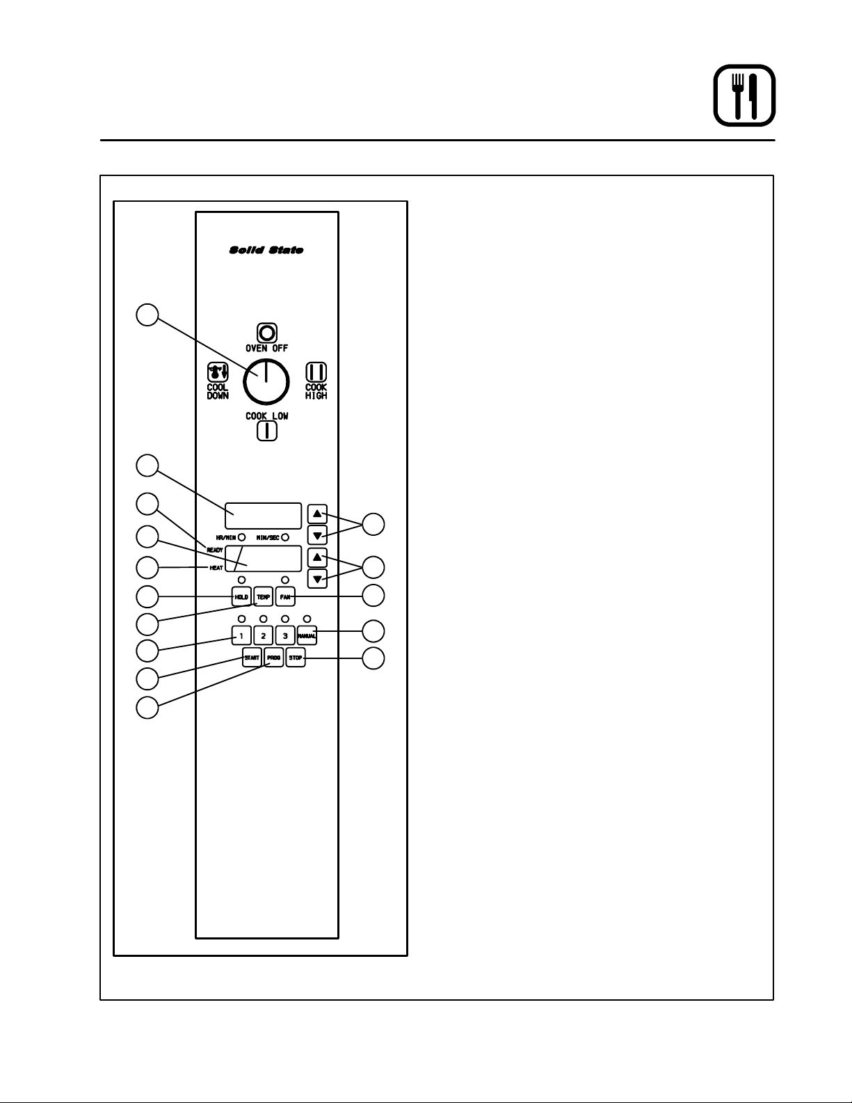
COMPONENT DESCRIPTION
1. SELECTOR SWITCH --- turns power to the
oven on or off. Allows selection of cook or cool
down modes and fan speed (if applicable).
2. TI M E DI SPL A Y --- g i v e s c o ok t i m e .
3. TIME ARROW KEYS -- - press to enter cook and/
1
2
4
5
6
8
9
3
7
10
12
15
or pulse times.
4. READY INDICATOR --- when lit indicates the
oven has reached the setpoint temperature
and product may be loaded.
5. TEMPERATURE DISPLAY --- gives cook and
hold temperatures.
6. HEAT INDICATOR --- when lit indicates the
oven is heating.
7. TEMPERATURE ARROW KEYS --- press to enter cook and hold temperatures.
8. HOLD KEY --- turns hold mode on or off.
9. TEMP KEY --- press to display actual oven
temperature.
10. F AN KEY --- turns pulse mode on or off. The
LED above the fan key is always on.
11. PRODUCT KEYS --- three programmable keys.
12. MANUAL PRODUCT KEY - -- default product key
used for manual operation.
13. START KEY --- press to begin a cook cycle.
14.PROGRAMKEY---presstoenterprogramming mode and save programmed settings.
15. STOP KEY --- press to silence audible alarms
and cancel cook cycles.
Figure 12
17

Operation
CH-Pro3 (Solid State Programmable Digital Control)
MANUAL OPERATION
NOTE: Press the arrow keys to change the cook
time and temperature at any point duringmanual operation.
Cook Only:
1. Turn the SELECTOR SWITCH (1) to the desired position.
2. Press the TIME ARROW KEYS (3) to enter the
cook time.
3. PresstheTEMPERATUREARROWKEYS(7)
to enter the cook temperature.
4. The READY INDICATOR (4) lights when the
oven is at the set temperature. Load product
into the oven.
5. Press the START KEY (13). The TIME DISPLAY
(2) counts down. The manual key LED flashes.
6. When the cook time expires the LEDs and
both displays flash and an audible alarm
sounds. Press t he STOP KEY (15) to silence
the alarm.
7. Remove the product.
Cook with Hold:
1. Turn the SELECTOR SWITCH (1) to the desired position.
2. Press the TIME ARROW KEYS (3) to enter the
cook time.
3. PresstheTEMPERATUREARROWKEYS(7)
to enter the cook temperature.
4. Press and hold the HOLD KEY (8) then release. Use the TEMPERATURE ARROW KEYS
(7) to enter the hold temperature. The hold key
LED lights. Press the hold key again to exit the
hold mode.
5. The READY INDICATOR (4) lights when the
oven is at the set temperature. Load product
into the oven.
6. Press the START KEY (13). The TIME DISPLAY
(2) counts down. The manual key LED flashes.
7. When the cook time expires both displays
flash and an audible alarm sounds for several
seconds then self cancels. The hold key LED
flashes. The time display begins to count up
while the oven cools to the hold temperature.
When the oven reaches the hold temperature
the time display resets to 00:00 then begins to
count up the hold time. The fan cycles with
heat demand in the hold mode.
8. Press the STOP KEY (15) to stop the timer.
9. Remove the product.
10. Push the HOLD KEY (8) to turn off hold mode.
Cook with Pulse:
1. Turn the SELECTOR SWITCH (1) to the desired position.
2. Press the TIME ARROW KEYS (3) to enter the
cook time.
3. PresstheTEMPERATUREARROWKEYS(7)
to enter the cook temperature.
4. Press the FAN KEY (10) for five seconds. The
TEMPERATURE DISPLAY (5) goes blank. The
fan key LED flashes. Use the TIME ARROW
KEYS (3) to enter the pulse time.
NOTE: Pulse time is a portion of the cook time
and does not increase the previously
entered cook time.
5. Pressthe FANKEY (10) again. The TEMPERATURE DISPLAY (5) lights.
6. The READY INDICATO R (4) in the temperature
display lights when the oven is at the set temperature. Load product into the oven.
7. Press the START KEY (13). The manual key
LED flashes. The TIME DISPLAY (2) counts
down the cook time. The fan cycles on for 30
seconds then off for 30 seconds until the set
pulse time has expired.
8. When the pulse time expires both displays
flash and an audible a larm sounds. Press the
STOP KEY (15) to silence the alarm.
9. Remove the product.
Oven Shut Down:
1. T urn the SELECTOR SWITCH (1) to OVEN OFF.
18

Operation
CH-Pro3 (Solid State Programmable Digital Control)
PROGRAMMING THE MANUAL KEY DEFA U LT
1. Turn the SELECTOR SWITCH (1) to the desired position.
2. Press the MANUAL KEY (12). The manual and
fan key LEDs light.
3. Press the TIME ARROW KEYS (3) to enter the
cook time.
4. PresstheTEMPERATUREARROWKEYS(7)
to enter the cook temperature.
5. For Cook and Hold --- Press and hold the
HOLD KEY (8). Use the TEMPERATURE ARROW KEYS (7) to enter t he hold temperature.
The hold key LED lights. Press the hold key
again to exit the hold mode.
For Cook with Pulse --- P r e s s t h e FA N KE Y
(10). Use the TIME ARROW KEYS (3) to enter
the pulse time. If no pulse is required, leave
pulsetimeat0:00.ThefankeyLEDflashes.
Press the fan key again to exit fan mode.
6. Press the PROGRAM KEY (14) to save the program settings.
MANUAL KEY DEFAULT OPERATION
1. Turn the SELECTOR SWITCH (1) to the desired position.
2. Press the MANUAL KEY (12). The applicable
LEDs light.
3. Press the START KEY (13). The TIME DISPLAY
(2) counts down. The manual key LED flashes.
NOTE: InCookwithPulsethefanLEDflashes.
NOTE: Press the arrow keys to change the
cook time and temperature at any
point during manual key operation.
4. When the cook time expires the applicable
LEDs and both displays flash and an audible
alarm sounds.
5. Press the STOP KEY (15) to silence the alarm.
NOTE: In Cook & Hold the alarm self cancels.
The oven cools to the hold temperature and the time display counts up.
6. Remove the product.
7. Turn the SELECTOR SWITCH (1) to OFF to
shut down the oven.
PROGRAMMING THE PRODUCT KEYS
1. Turn the SELECTOR SWITCH (1) to the desired position.
2. Press the des ired PRODUCT KEY (11). The
product and fan key LEDs light.
3. Press and hold the PROGRAM KEY (14) until
the corresponding LED flashes, approximately five seconds.
4. Press the TIME ARROW KEYS (3) to enter the
cook time.
5. PresstheTEMPERATUREARROWKEYS(7)
to enter the cook temperature.
6. For Cook and Hold --- Press and hold the
HOLD KEY (8). Use the TEMPERATURE ARROW KEYS (7) to enter t he hold temperature.
The hold key LED lights. Press the hold key
again to exit the hold mode.
For Cook with Pulse --- P r e s s t h e FA N KE Y
(10). Use the TIME ARROW KEYS (3) to enter
the pulse time. If no pulse is required, leave
pulsetimeat0:00.ThefankeyLEDflashes.
Pressthefankeyagaintoexitthefanmode.
7. Press the PROGRAM KEY (14) to save the program settings.
PRODUCT KEY OPERATION
1. Turn the SELECTOR SWITCH (1) to the desired position.
2. Press the des ired PRODUCT KEY (11). The
applicable LEDs light.
3. Press the START KEY (13). The TIME DISPLAY
(2) counts down. The product key LED flashes.
NOTE: InCookwithPulsethefanLEDflashes.
4. When the cook or pulse time expires the applicable LEDs and both displays flash and an audible alarm sounds.
5. Press the STOP KEY (15) to silence the alarm.
NOTE: In Cook and Hold the alarm self can-
cels. The oven cools to the hold temperature and the time display counts
up.
6. Remove the product.
7. Turn the SELECTOR SWITCH (1) to OFF to
shut down the oven.
19
Operation
Solid State Digital Control
1
2
3
CONTROL DESCRIPTION
1. SELECTOR SWITCH --- turns power to the
oven on or off. Allows selection of Cook or
Cool Down Modes and fan speed (if applicable).
2. DISPLAY --- displays time or temperature and
other information related to oven function.
3. HEAT LAMP --- lights when heater is on.
4. PULSE LAMP -- - lights when Pulsed Fan Mode
is turned on.
5. HOLD LAMP --- lights when Hold Mode is
turned on.
6. DIAL --- used to enter set points in display
7. START/STOP KEY --- s tarts or stops the timer.
8. TIME KEY --- used to show time in the display.
9. TEMP KEY --- used to show set temperature in
the display.
NOTE: Actual temperature is shown while the
4
10. HOLD KEY --- turns Hold Mode on or off.
5
11. PULSE KEY --- turns Pulse Mode on or off.
TEMP key is held down.
10
PROGRAMMING
8
7
Figure 13
6
9
11
To set the cook temperature:
1. Press TEMP (9) key.
2. Rotate dial (6) to enter temperature.
To set the cook time:
1. Press TIME (8) key.
2. Rotate the dial (6) to enter time.
NOTE: Time is entered in hours : minutes or
minutes : seconds.
To set the hold time:
1. Press HOLD key (10) to turn hold mode on.
NOTE: HOLD light is on.
2. Rotate dial (6) to enter the hold temperature.
3. Press START/STOP key (7)
To s et the pul s e tim e:
1. Press PULSE KEY (11) to turn pulse mode on.
NOTE: Pulse light is on.
2. Rotate DIAL (6) to enter the pulse time. Pulse
time is a portion of the pre-set cook time.
20

Operation
Solid State Digital Control
OPERATION
Cook Only:
1. Turn the SELECTOR switch (1) to the desired
position.
2. Enter the cook time and temperature.
3. Load product into t he oven.
NOTE: The display reads LOAD when the
oven is near the set temperature.
4. Press the START/STOP key (7). The t imer begins to count down.
5. When the cook timer reaches 00:00 the buzzer sounds and the display reads DONE.
6. Press the START/STOP key (7) to silence the
buzzer.
7. Remove the product.
Cook with Hold:
NOTE: HOLD light is on when hold mode is on
and off when hold mode is off.
1. Turn the SELECTOR switch (1) to the desired
position.
2. Enter the cook time and temperature.
3. Press the HOLD key (10). Enter the hold temperature.
4. Load product into t he oven.
NOTE: The display reads LOAD when the
oven is near the set temperature.
5. Push the START/STOP (7) key. Timer begins
to count down.
6. When the cook timer reaches 00:00 the buzzer sounds and the display reads DONE. The
buzzer turns off after a few seconds. The display reads HOLD until the oven reaches the
hold temperature. Then the timer begins to
count up.
7. Push the START/STOP key (7) to stop timer.
8. Remove the product.
9. Push HOLD (10) key to turn off hold mode.
Cook with Pulse:
NOTE: PULSE light is on when pulse mode is on
andoffwhenpulsemodeisoff.
1. Turn the SELECTOR SWITCH (1) to the desired position.
2. Enter cook time and cook temperature.
3. Press PULSE KEY (11). Enter the pulse time.
NOTE: Pulse time is a portion of the cook time
and does not increase the previously
entered cook time.
4. Load product into t he oven.
NOTE: The display reads LOAD when the
oven is near the set temperature.
5. Push START/STOP K EY (7). The timer begins
to count down the cook time. The oven will be
inpulsemodeforthesetpulsetime.Oncethe
set time has expired, the unit will automatically
switch to cook mode and continue counting
down.
6. When the cook timer reaches 00:00 the buzzer sounds and the display reads DONE.
7. Push the START/STOP KEY (7) to turn the
buzzer off.
8. Remove the product.
WARNING!!
Acompletefiveminuteshutdownmustbe
observed before the oven is relighted.
21
Operation
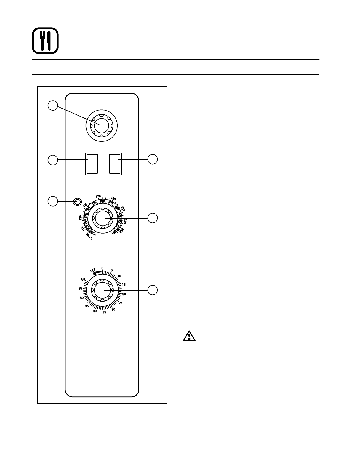
Solid State Manual Control
1
3
4
COOL
DOWN
LIGHT OFF
OVEN READY
OVEN OFF
ON
OFF
LIGHTS
SOLID STATE
THERMOSTAT
TIMER
COOK
HI
LO
BLOWER
2
60 Hz
Only
5
6
CONTROL DESCRIPTION
1. SELECTOR SWITCH --- controls power to the
oven for cook or cool down.
2. BLOWER SWITCH --- controls blower speed, either hi or lo. T wo speed not available in 50 Hz.
3. LIGHTS SWITCH --- controls interior lights.
4. OVEN READY LIGHT --- when lit indicates
burner operation. When the light goes out the
oven has reached operating temperature.
5. SOLID STA TE THERMOSTAT --- allows either 8
pre-set temperatures to be selected in accordance with customer requirements, or an infinite selection of temperatures from 200-500_F
(95-260_C). (infinite control shown)
6. TIMER --- activates an electric buzzer that
sounds when the cook time expires.
OPERATION
1. Turn the SELECTOR Switch (1) to COOK.The
blower and control compartment cooling fan
operate and are controlled automatically by
the action of the doors.
2. Set BLOWER Switch (2) to the desired speed.
3. Set the SOLID STATETHERMOSTAT(5) to the
desired setting or temperature.
4. Preheat until the OVEN READY LIGHT (4)
goes out.
5. Load product into the oven. Determine cook
time and set the TIMER (6).
6. When the buzzer sounds, remove the product
fromthe oven. Turnthe TIMER knob (6) to OFF
to silence the buzzer.
7. Turn the SELECTOR Switch (1) to OVEN OFF.
Figure 14
WARNING!!
Acompletefiveminuteshutdownmustbe
observed before the oven is relighted.
22
2
7
8
10
11
17
18
Operation
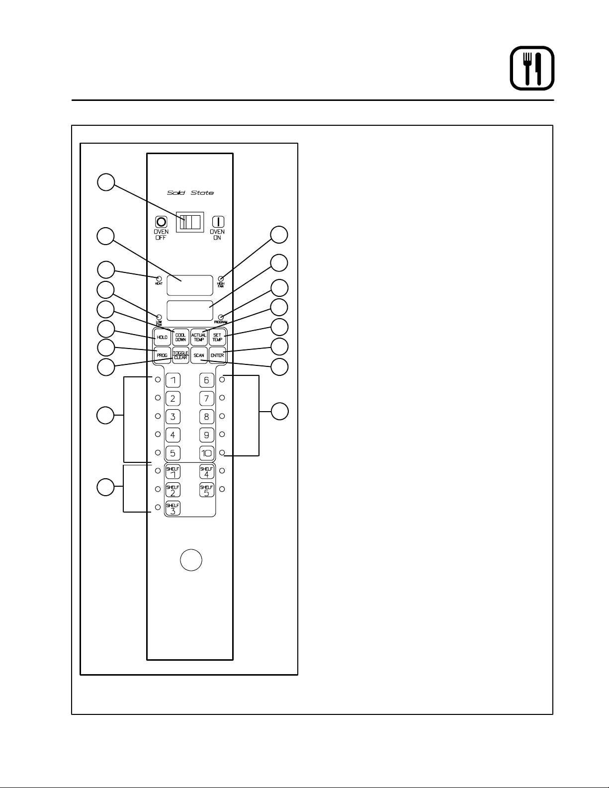
Blodgett IQ2T Control
COMPONENT DESCRIPTION
1. OVEN POWER SWITCH --- controls power to
1
3
6
9
4
5
12
13
14
15
16
the oven.
2. TOP DISPLAY --- displays temperature and
other controller related information.
3. FAN HI LED --- when lit indicates the fan is run-
ning at high speed.
4. B O T T O M DI SPL A Y --- d is p la ys co o k ti m e an d
other controller related information.
5. PROG LED --- when lit indicates the controller
is in the programming mode.
6. HEAT LED --- when lit indicates the control is
calling for heat.
7. FAN LOLED --- when litindicates the fan is run-
ning at low speed.
8. COOL DOWN KEY --- press to enter the cool
down mode.
9. HOLD KEY --- press to enter hold mode.
10. PROG KEY --- press to enter the programming
mode.
11. TOGGLE/CLEAR KEY --- press during pro-
gramming to toggle options.
12. ACT TEMP KEY --- press to display the actual
oven temperature.
13. SET TEMP KEY --- press to display the pro-
grammed cook temperature for the current
stage of the product key.
14. ENTER KEY --- press to enter new values into
product key programming. Also used to view
recovery time.
15. SCAN KEY --- completes the programming for
the current parameter and advances the con trollerto the next parameter.Press to view time
remaining on multiple cook cycles.
16. PRODUCT LEDS --- when lit indicate which
product keys are currently in use or programmed for the current oven temperature
and fan speed.
17. PRODUCT KEYS --- assigns a key to a pro-
grammed recipe and begins a programmed
cooking process.
18. SHELF KEYS --- assigns a shelf key.
Figure 15
23

Operation
Blodgett IQ2T Control
OVEN OPERATION
Oven Startup:
1. Toggle the POWER SWITCH (1) to ON.The
oven preheats to the lowest programmed first
stage temperature. The LEDS (16) for all products with the same first stage temperature light.
While the unit preheats the TOP DISPLAY (2)
gives the set temperature. The BOTTOM DISPLAY (4) reads Lo iftheovenismorethan10_
below setpoint. When the oven reaches ¦10_
of the preheat temperature an alarm sounds
and the bottom display reads Ready.
Single Product Cooking Procedure:
NOTE: If the led next to the desired product key i s
lit skip step 1.
1. Press the desired PRODUCT KEY (17). The
oven preheats to the first stage temperature for
the selected product. When the oven reaches
¦10_ of the preheat temperature an alarm
sounds and the bottom display reads Ready .
2. Load the product into the oven. Press the desired PRODUCT KEY (17).
If the shelf timing function is toggledon for that
product key, the top display reads SHLF and
the bottom display reads the programmed
product’s time. Press a SHELF K EY (18) to assign the product to that shelf and start the
cook cycle. The top display reads SHLF,the
bottom display gives the shelf #. Within five
seconds, the top display reads SH-1,thebottom display gives the remaining cook time.
If the shelf timing function is toggled off for that
product key, pressing the product key will
start the cook cycle. The TOP DISPLAY (2)
re a d s --- --- --- --- . T h e B O T T O M D I S P L AY (4 )
counts down the cook time in minutes: seconds.
NOTE: If the selected product has a cook time
of greater than 59:59 the top display
r e ad s H r --- --- f o r the to t a l nu m b e r of
hours. The bottom display counts down
the cook time in minutes:seconds.
NOTE: If the selected product is a single stage
recipe the LEDS for all single stage
products with the same cook tempera-
ture and fan speed will light. If the selected product is a multiple stage recipe no other product LEDS will light.
NOTE: Press and hold the selected product
key for three seconds to cancel the
cook cycle for normal operation. To
cancel the cook cycle when using
shelf timing, press and hold the
SHELF KEY (18) for 3 seconds or
press TOGGLE/CLEAR (11) and the
corresponding shelf key.
3. When the cook time expires an alarm sounds
and the top display reads donE.
4. Press the selected product key to silence the
alarm. Remove the product. If shelf timing is
used, press the flashing SHELF KEY (18) to silence the alarm.
Multiple Batch Cooking Procedure:
This procedure is for single stage recipes with the
same cook temperature and fan speed only.
NOTE: If the led next to the first desired product
key is lit skip step 1.
1. Press the first desired PRODUCT KEY (17).
The LEDS for all recipes with the same cook
temperature and fan speed will light.
The oven preheats to the cook temperature for
the selected product. When the oven reaches
¦10_ of the preheat temperature an alarm
sounds and the bottom display reads Ready.
2. Load the product into the oven. Press the desired PRODUCT KEY (17).
If the shelf timing function is toggledon for that
product key, the top display reads SHLF and
the bottom display reads the programmed
product’s time. Press a SHELF K EY (18) to assign the product to that shelf and start the
cook cycle. The top display reads SHLF,the
bottom display gives the shelf #. Within five
seconds, the top display reads SH-1,thebottom display gives the remaining cook time.
If the shelf timing function is toggled off for that
product key, pressing the product key will
start the cook cycle. The TOP DISPLAY (2)
re a d s --- --- --- --- . T h e B O T T O M D I S P L AY (2 )
counts down the cook time in minutes: seconds.
24

Operation
Blodgett IQ2T Control
3. Load the second product. Press the appropriate PRODUCT KEY (17). Press a SHELF KEY
(18) to activate shelf timing.
NOTE: Only products with lighted LEDS may
be selected.
4. The top display reads SHLF. The bottom dis-
play gives the numbers of the shelves that
have been assigned. Within five seconds the
shelf with the least amount of time remaining
is displayed. The led for the product with the
least time remaining flashes faster than the led
for the other products.
NOTE: To view the remaining cook time for
the other products press and hold the
SCAN KE Y (15). The bottom display
cycles through the remaining cook
times for each product. Only the led
for the product with the cook time displayed will be lit.
5. When a cook time expires an alarm sounds.
The top display reads donE.Theledforthefinished product lights. All other LEDS are dark.
6. Press the SHELF KEY (18) for the finished
product to silence the alarm. Remove the
product. Close the oven door. The TOP DISPLAY (2) reads SH-X for the shelf with the least
amount of cook time. The BOTTOM DISPLAY
(4) counts down the cook time for t he other
product.
7. When the cook time expires an alarm sounds
and the top display reads donE.
8. Press the SHELF KEY (18) to silence the
alarm. Remove the product.
Oven Cool Down:
1. Close the oven door . Press the COOL DOWN
KEY (8).
NOTE: Cool down cannot be activated with the
oven door open. Once the cool down cycle
has begun the doors may be opened to
speed the cooling process.
25

Operation
Blodgett IQ2T Control
PROGRAMMING SINGLE STAGE RECIPES
Entering the Programming Mode:
1. Press and hold the PROG KEY (10). The top
display reads CodE.
2. Use the product keys to enter the programming access code: 3 1 2 4. Press the ENTER
KEY (14). The top display reads Prod.
3. Press the desired product key followed by the
ENTER KEY (14).
NOTE: During the programming process you may:
Press the TOGGLE/CLEAR KEY (11) to
erase the current setting or toggle between specific settings. Press the SCAN
KEY (15) to move to the next programming
function keeping the current setting the
same. Press the PROG KEY (10) to exit the
programming mode.
Programming the Cook Time:
1. The top display reads P1:__. The bottom display gives the current programmed cook time
for stage 1 in minutes:seconds. Press the
TOGGLE/CLEAR KEY (11). Use the product
keys to enter the new cook time. Press the ENTER KEY (14) to save the new cook time.
2. The top display reads P2:__. The control is
asking for the cook time for stage 2 of this recipe. Press the TOGGLE/CLEAR KEY (11) to
enter a time of 0:00:00 for P2:.
NOTE: This tells the controller that there are
no more stages for this recipe. Once
a single stage recipe has been established the control will only allow entries for one stage on all further parameters for this product.
3. Press the ENTER KEY (14) again. The t op display reads P1:. The bottom display shows the
cook time.
4. Press t he SCAN KEY (15) to advance the pro gramming mode to cook temperature.
Programming the Cook Temperature:
1. The top display reads C t --- 1 . The bottom dis-
play gives the current cook temperature. Use
the product keys to enter the desired cook
temperature.
2. Press t he SCAN KEY (15) to advance the pro gramming mode to fan speed.
Programming the Fan Speed:
1. The top display reads SPd1. The bottom display gives the current fan speed. Press the
TOGGLE/CLEAR KEY (11). The bottom display toggles between HI and Lo.
2. Press t he SCAN KEY (15) to advance the pro gramming mode to the fan cycle time.
Programming the Fan Cycle Time:
There are 3 options for fan cycle time: Pulse, Heat
and Full. Pulse allows the fan to turn on and off as
programmed. Heat allows the fan to operate with
heat only. Full provides continuous fan operation.
1. The top display reads CYC1. The bottom display gives the current fan cycle. Press the
TOGGLE/CLEAR KEY (11). The bottom display toggles between PULS, HEAt and FULL.
2. If heat or full are selected press the SCAN KEY
(15) to save the new fan cycle and advance to
timing mode.
If pulse is selected press the SCAN KEY (15)
and continue with Steps 3---4 to program the
pulse cycle.
3. The top display reads o n --- 1 . The bottom display gives the current pulse on time. Use the
product keys to enter the desired pulse on
time from 10 to 60 seconds. Press the SCAN
KEY (15).
4. The top display reads o f --- 1 . The bottom display gives the current pulse off time. Use the
product keys to enter the desired pulse off
time from 10 to 60 seconds. Press the SCAN
KEY (15) to advance the programming mode
to shelf mode.
26

Operation
Blodgett IQ2T Control
Programming the Shelf ID:
The Shelf ID option can be turned on or off for specific product keys.
NOTE: Shelf ID is not allowed with multiple stage
recipes.
1. The top display reads SHLF. The bottom dis-
play reads the current shelf ID mode. Press
the TOGGLE/CLEAR KEY (11) to toggle between yes a nd no. Press the SCAN KEY (15)
to advance the programming mode to timing.
Programming the Timing Mode:
There are 3 options for timing mode: Straight, Flex
and Sensitivity.
1. The top display reads t C --- 1 . The bottom dis-
play gives the current timing mode. Press the
TOGGLE/CLEAR KEY (11) to toggle between
St, FL and SEns.
NOTE: Sensitivity adjusts the cook time to
compensate for any difference between the setpoint and actual temperature. The lower the sensitivity value
the shorter the time adjustment. Sensitivity values are set in the manager level programming.
If Shelf ID is activated, all three timing modes
are available. If Shelf ID is not activated, only
straight or flex timing modes are available.
2. Press t he SCAN KEY (15) to advance the pro gramming mode to hold mode.
Programming Hold Mode:
The hold mode can be toggled on or off for specific
product k eys.
1. The top display reads HOLD. The bottom dis-
play reads the current hold mode. Press
TOGGLE/CLEAR KEY (11) to toggle between
on and off. Press the SCAN KEY (15).
2. If the hold mode is a ctivated, the bottom display give the current hold time. Press the
TOGGLE/CLEAR KEY (11). Use the product
keys to enter the new hold time. Press the
SCAN KEY (15).
3. The bottom display gives the current hold
temperature. Press the TOGGLE/CLEAR KEY
(11). Use the product keys to enter the new
hold temperature from 140-210_F(60-99_C).
Press the SCAN KEY (15).
4. The top display reads HFAN (hold fan speed).
The bottom display gives t he current hold fan
speed setting. Press the TOGGLE/CLEAR
KEY (11) to toggle between high and low.
Press the SCA N KEY (15) to exit the hold
mode programming.
Check all Settings (SEE Mode):
TheSEEmodeallowstheoperatortoscrollthrough
and view settings of a particular product key.
1. Press the PROG KE Y (10). The top display
reads Code.
2. Use the product keys to enter the SEE access
code: 2 4 4 4. Press the ENTER KEY (14). The
top display reads SEE.
3. Press the product key you wish to view. Press
the ENTER KEY (14).
4. The control will automatically scroll through
the programmable features showing the programmed values for each.
Exiting the programming mode:
1. The top display reads Prod. Press the PROG KEY
(10). The control returns to operating mode.
27

Operation
Blodgett IQ2T Control
PROGRAMMING MULTIPLE STAGE RECIPES
Entering the Programming Mode:
1. Press and hold the PROG KEY (10). The top
display reads CodE.
2. Use the product keys to enter the programming access code: 3 1 2 4. Press the ENTER
KEY (14). The top display reads Prod.
3. Press the desired product key followed by the
ENTER KEY (14).
Programming the Cook Time:
NOTE: When multiple stage cooking is being
used, the countdown time displayed during cooking is the sum of all stages.
1. The top display reads P1:__. The bottom display gives the current programmed cook time
for stage 1 in minutes:seconds. Press the
TOGGLE/CLEAR KEY (11). Use the product
keys to enter the new cook time. Press the ENTER KEY (14) to save the new cook time.
2. The top display reads P2:__. The control is
asking for the cook time for the second stage
of this recipe. Repeat Step 1 for each additional stage.
3. When the cook times for all stages are programmed, press the TOGGLE/CLEAR KEY
(11) to clear the bottom display.
NOTE: This tells the controller that there are
no more stages for this recipe. Once
the number of stages has been established the control will only allow entries for these stages on all further parameters for this product.
4. Press the ENTER KEY (14) again. The display
reads P1:. The bottom display shows the cook
time.
5. Press t he SCAN KEY (15) to advance the pro gramming mode to cook temperature.
Programming the Cook Temperature:
1. The top display reads C t --- 1 . The bottom dis-
play gives the current cook temperature for
stage 1 of this recipe. Use the product keys to
enter the desired cook temperature.
2. Press the ENTER KEY (14) to save the new
cook temperature for stage 1. The top display
re a d s Ct --- 2 .
NOTE: Repeat Steps 1---2 to program the
cook temperature for additional
stages. When the cook temperature
for the final stage has been entered
the top display reads Ct---1.
3. Press t he SCAN KEY (15) to advance the pro gramming mode to fan speed
Programming the Fan Speed:
1. The top display reads SPd1. The bottom display gives the current fan speed. Press the
TOGGLE/CLEAR KEY (11). The bottom display toggles between HI and Lo.
2. Press t he SCAN KEY (15) to advance the pro gramming mode to the fan cycle time.
28

Operation
Blodgett IQ2T Control
Programming the Fan Cycle Time:
There are 3 options for fan cycle time: Pulse, Heat
and Full. Pulse allows the fan to turn on and off as
programmed. Heat allows the fan to operate with
heat only. Full provides continuous fan operation.
1. The top display reads CYC1. The bottom dis-
play gives the current fan cycle for stage 1.
Press the TOGGLE/CLEAR KEY (11). The bottom display toggles between PULS, HEAt and
FULL.
2. Press the ENTER KEY (14) to save the new fan
cycle for stage 1. The top display reads CYC2.
NOTE: Repeat Steps 1 ---2 to program the fan
cycle for additional stages.
3. Whenthe fan cycle for the final stage has been
entered press the SCAN KEY (15).
If no pulse cycles are programmed the control
advances to timing mode.
If pulse is used, the control returns to the first
stage programmed for the pulse fan option.
Follow Steps 4---5 to program the pulse on
and off time.
4. The top display reads o n --- x . The bottom display gives the current pulse on time for this
stage. Use the product keys to enter the desired pulse on time from 10 to 60 seconds.
Press the SCAN KEY (15).
5. The top display reads o f --- x . The bottom display gives the current pulse off time. Use the
product keys to enter the desired pulse off
time from 10 to 60 seconds. Press the SCAN
KEY (15). The control advances to the next
stageprogrammedforthepulsefanoption.
NOTE: Repeat Steps 4 --- 5 to program cycle
times for all pulse fan stages. When the
final pulse off time has been entered the
control advances to timing mode.
Programming the Timing Mode:
NOTE: It may be necessary to press the ENTER
KEY (14) until the top display reads tC---1.
There are 2 options for timing mode: Straight and
Flex.
1. The top display reads t C --- 1 . The bottom dis-
play gives the current timing mode. Press the
TOGGLE/CLEAR KEY (11) to toggle between
St,andFL.
2. Press the ENTER KEY (14) to save the new
timingmode for stage 1. The top display reads
tC --- 2 .
NOTE: Repeat Steps 1 ---2 to program the tim-
ing mode for additional stages.
3. When the timing mode for the final stage has
been entered press the SCAN KEY (15).
Programming Hold Mode:
The hold mode can be toggled on or off for specific
product k eys.
1. The top display reads HOLD. The bottom display reads the current hold mode. Press
TOGGLE/CLEAR KEY (11) to toggle between
on and off. Press the SCAN KEY (15).
2. The bottom display give the current hold time.
Press the TOGGLE/CLEAR KEY (11). Use the
product keys to enter the new hold time. Press
the SCAN KEY (15).
3. The bottom display gives the current hold
temperature. Press the TOGGLE/CLEAR KEY
(11). Use the product keys to enter the new
hold temperature from 140-210_F(60-99_C).
Press the SCAN KEY (15).
4. The top display reads HFAN (hold fan speed).
The bottom display gives t he current hold fan
speed setting. Press the TOGGLE/CLEAR
KEY (11) to toggle between high and low.
Press the SCA N KEY (15) to exit the hold
mode programming.
Exiting the programming mode:
1. The top display reads Prod. Press the PROG
KEY (10). The control returns to operating
mode.
29

Operation
Blodgett IQ2T Control
MANAGER LEVEL PROGRAMMING
Entering the programming mo de
1. Press the PROG KE Y (10). The top display
reads CodE.
2. Use the product keys to enter the programming access code: 4 5 1 2. Press the ENTER
KEY (14). The top display reads SYS.
Programming hold
Hold allows product to be kept warm in the oven
at a programmed time and temperature by pressing the HOLD KEY (9).
1. Press the SCAN KEY (15). The top display
reads Hold. Press the TOGGLE/CLEAR KEY
(11) to toggle between YES and no.Pressthe
SCAN KEY (15).
If no is chosen:
a.) Press the SCAN KEY (15) to advance to
programming the setback mode.
Ifyesischosen:
a.) The top display reads HOLD. The bottom
display gives the current hold time. Press
the TOGGLE/CLEAR KEY (11). Use the
product keys to enter a hold time from 0
to 9 hours. Press the SCAN KEY (15) to
enter the new hold time (HR:MN)..
b.) The top display reads HOLD. The bottom
display gives the current hold temperature. Press the TOGGLE/CLEAR KEY (11).
Use the product k eys to enter a hold temperature from 140_F --- 210_F. P r e s s t h e
SCAN KEY (15) to enter the new hold temperature.
c.) The top display reads HFAn. The bottom
display gives the current fan mode. To
change the fan mode press the TOGGLE/
CLEAR KEY (11). The bottom display
toggles between Hi and Lo.Pressthe
SCAN KEY (15) to enter the new fan mode
and continue with programming the setback mode.
Programming the setback mode
The setback mode operates as a power saving
feature. After a period of non-use (the setback
time) the oven temperature automatically de creases to t he setback temperature. The oven will
maintain this temperature until a product key is
pressed. The minimum setback time is 20:00.
1. The top display reads SEtb. The bottom dis-
play gives the setback mode. To change the
setback press the TOGGLE/CLEAR KEY (11).
The bottom display toggles between YES and
no. Press the SCAN KEY (15).
If no is chosen:
a.) The controller advances to programming
the temperature mode.
Ifyesischosen:
a.) The bottom display gives the current set-
back time. Press the TOGGLE/CLEAR
KEY (11). Use the product keys to the enter the desired setback time. Press the
SCAN KEY (15) to enter the new setback
time.
b.) The bottom display gives the current set-
back temperature. Press the TOGGLE/
CLEAR KEY (11). Use the product keys to
the enter a setback temperature from
140_F --- 30 0 _F. P r e s s th e SC A N K E Y ( 1 5 ) t o
enter the new setback and continue with
programming the temperature mode.
Programming the temperature mode (_For_C)
1. The top display reads dEg. The bottom dis-
play gives the units. To change the units press
the TOGGLE/CLEAR KEY (11). The bottom
display toggles between F and C.
2. Press the SCAN KEY (15) to enter the new
temperature units and continue programming
the shelf sensitivity.
30

Operation
Blodgett IQ2T Control
Programming the shelf sensitivity
The controller allows the user to program a sensitivity value (0--- 9) for each shelf position. The sensitivity value will shorten or stretch cook time depending upon shelf position.
NOTE: SEN1 is the top shelf position, SEN5 is the
bottom shelf position.
1. The display reads SEN1.
2. Press the TOGGLE/CLEAR KEY (11) to clear
the current value to the desired value. Use the
product key numbers to input a new sensitivity
value.
3. Press the SCAN KEY (15) to advance to the
next shelf position, SEN2.
4. Repeat steps 2---3 for all five shelf positions.
Exiting the programming mode
1. The top display reads SYS.PressthePROG
KEY (10). The control returns to the operating
mode.
ERROR CODES AND A LARMS
NOTE: The error codes will appear in the top dis-
play. All error codes are accompanied by
an audible alarm.
Hi Oven temperature is more than
40_F above the highest setpoint.
Prob Probe failure.
HEAT ERR F rom a cool start (below 140_F), the
oven takes more than 10 minutes to
climb from 150-300_F. P r e s s t h e
TOGGLE/CLEAR KEY (11) to clear
the prompt. This code indicates a
problem with t he system. Contact a
service technician.
FAN ERR Indicates a fan failure during a call
for heat. Press the TOGGLE/CLEAR
KEY (11) to clear the alarm. The FAN
ERR display remains active. Press
the TOGGLE/CLEARKEY (11) again
to clear the message and return the
system to normal operation. If condition persists turn off the oven and
contact a service technician.
FANC ERR Indicates a contact failure has oc-
curred in the fan control circuit.
Press the TOGGLE/CLEARKEY(11)
to clear the alarm. The FANC ERR
display remains active. Press the
TOGGLE/CLEAR KEY (11) again to
clear the message and return the
system to normal operation. If condition persists turn off the oven and
contact a service technician.
DOOR OPEN The controller senses the door is
open. Close the door. If the door is
closed contact a service technician.
31

Operation
Cook and Hold Control
1
3
COOL
DOWN
LIGHT OFF
OVEN READY
OVEN OFF
COOK & HOLD
ON
OFF
LIGHTS
THERMOSTAT
COOK
COOK
CONTROL DESCRIPTION
1. SELECTOR SWITCH --- controls power to the
oven for cook, cook & hold, and cool down.
2. LIGHTS SWITCH --- controls interior lights.
3. OVEN READY LIGHT --- when lit indicates
burner operation. When the light goes out, the
oven has reached operating temperature.
4. COOK THERMOSTAT --- controls oven tem-
2
perature in the cook cycle.
5. COOK TIMER --- activates an electric buzzer
that sounds when the cook time expires.
6. HO L D TH E R M O S TA T --- co n t r o l s ov e n te m perature in the hold cycle.
7. HOLD LIGHT - indicates the oven is in hold.
8. COOK & HOLD TIMER --- controls the length
of cook time from 0 to 12 hours. When the
4
cook time ends, oven temperature control
switches from the cook to the hold thermostat.
COOK TIMER
5
HOLD
LIGHT
6
HOLD
THERMOSTAT
7
COOK & HOLD
TIMER
8
Figure 16
32

Operation
Cook and Hold Control
OPERATION
Cook Only:
1. Turn the SELECTOR SWITCH (1) to COOK.
The blower and control compartment cooling
fans operate and are controlled automatically
by the action of the doors.
2. Set the COOK THERMOSTAT (4) to the desired temperature.
3. Preheat until the OVEN READY LIGHT (3)
goes out.
4. Load product into the oven. Set the COOK
TIMER (5) to the desired cook time.
5. When the buzzer sounds, remove the product. Turn the COOK TIMER (5) to OFF to silence the buzzer.
6. Turn the SELECTOR SWITCH (1) to OVEN
OFF.
Cook and Hold:
1. Turn the SELECTOR SWITCH (1) to COOK.
The blower and control compartment cooling
fans operate and are controlled automatically
by the action of the doors.
2. Set the COOK THERMOSTAT (4) to the desired cook temperature.
3. Set th e HOLD THERMOSTAT (6) to the desired hold temperature.
4. Preheat the oven until the OVEN READY
LIGHT (3) goes out.
5. Load product into t he oven.
6. Turn SELECTOR Switch (1) to COOK & HOLD.
7. Set the COOK & HOLD TIMER (8) to the desired cook time.
8. When the cook time ends the oven switches
to HOLD and the HOLD LIGHT (7) comes on.
9. The oven remains at the hold temperature until the product is removed and the oven is
turned off.
NOTE: In the HOLD cycle, the blower goes on
and off with the burner.
10. Turn the SELECTOR SWITCH (1) to OVEN
OFF.
COOL DOWN
1. For COOL DOWN operation set the SELECTOR SWITCH (1) to COOL DOWN.
WARNING!!
Acompletefiveminuteshutdownmustbe
observed before the oven is relighted.
33

Operation
Pulse Plus
1
3
4
COOL
DOWN
OVEN OFF
ON
OFF
LIGHTS
FAN DE LAY TI ME R
HI
LO
BLOWER
COOK
2
60Hz
Only
5
CONTROL DESCRIPTION
1. SELECTOR SWITCH --- controls power to the
oven for cook or cool down.
2. BLOWER SWITCH --- controls blower speed,
either hi or lo. T wo speed not available in 50 Hz.
3. LIGHTS SWITCH --- controls interior lights.
4. AMBER FAN DELAY LIGHT --- indicates the
oven is in pulse plus.
5. FAN DELAY TIMER --- activates pulse plus for
0---10 minutes. The blower and burners pulse
on for 30 seconds and off for 30 seconds for
the duration of time set.
6. REDINDICATORLIGHT --- indicatesovenisin
the cook timer cycle.
7. COOK TIMER --- activates an electric buzzer
that sounds when the cook time expires.
8. OVEN READY LIGHT --- when lit indicates
burner operation. When the light goes out, the
oven has reached operating temperature.
9. SOLID STATE THERMOSTAT --- allows either
8 pre-set temperatures to be selected in accordance with customer requirements, or an
infinite selection of temperatures from
0-500_F (0-260_C). (infinite control shown)
6
8
LIGHT OFF
OVEN READY
TIMER
SOLID STATE
THERMOSTAT
Figure 17
OPERATION
7
1. Turn the SELECTOR Switch (1) to COOK.
2. Set the SOLID STATETHERMOSTAT(9) to the
desired cook temperature.
3. Preheat the oven until the OVEN READY
LIGHT (8) goes out.
4. Load product into t he oven.
5. Set FAN DELAY TIMER (5) for the desired time
for pulse plus operation.
9
6. Set the COOK TIMER (7) for the desired cook
time.
7. When the buzzer sounds, remove product
fromthe oven. Turnthe TIMER (7) knob to OFF
to silence the buzzer.
8. Turn the SELECTOR SWITCH (1) to OVEN
OFF.
WARNING!!
Acompletefiveminuteshutdownmustbe
observed before the oven is relighted.
34

1
3
6
COOL
DOWN
LIGHT OFF
OVEN READY
STEAM ON
OVEN OFF
ON
OFF
LIGHTS
SOLID STATE
THERMOSTAT
TIMER
STEAM
CYCLE START
COOK
Operation
Humidaire
CONTROL DESCRIPTION
1. SELECTOR SWITCH --- controls power to the
oven for cook or cool down.
2. LIGHTS SWITCH --- controls interior lights.
3. OVEN READY LIGHT --- when lit indicates
burner operation. When the light goes out, the
oven has reached operating temperature.
4. SOLID STATE THERMOSTAT - allows either 8
pre-set temperatures to be selected in accor-
2
4
5
7
8
dance with customer requirements, or an infinite selection of temperatures from 200 -500_F
(95-260_C). (infinite control shown)
5. TIMER --- activates an electric buzzer that
sounds w hen the timer expires to alert the operator to remove the product.
6. STE A M O N I N D I C A T O R L I G H T --- li g h t s w h e n
steam is being injected into the oven.
7. STEAM CYCLE START BUTTON --- activates
steam injection for one complete cycle.
8. STEAM CYCLE TIME SWITCH --- sets desired
length of steam cycle from 0 to 30 seconds.
OPERATION
1. Turn the SELECTOR SWITCH (1) to COOK.
2. Set the SOLID STATETHERMOSTAT(4) to the
desired cook temperature.
3. Preheat until OVEN READY light (3) goes out.
4. Load product into the oven. Set the TIMER (5)
to the desired cook time.
5. Set the STEAM CYCLE TIME SWITCH (8) for
the desired length of steam injection.
6. Press STEAM CYCLE START (7). When the
temperature is at or above 225_F (107_C), the
solenoidvalve opens. The blue STEAM ON indicatorlight (6) comes on. The steam injection
cycle may be repeated as often as desired.
7. When the buzzer sounds, remove the prod-
uct. Turn the TIMER (5) to OFF to silence the
buzzer.
8. T urn the SELECTOR SWITCH (1) to OVEN OFF.
STEAM
CYCLE TIME
Figure 18
WARNING!!
Acompletefiveminuteshutdownmustbe
observed before the oven is relighted.
35

Operation
Intelliplus with Chain Event Control
1
2
3
4
5 6
7
8
CONTROL DESCRIPTION
1. SELECTOR SWITCH --- controls power to the
oven for cook or cool down.
2. LIGHTS SWITCH --- controls interior lights.
3. OVEN READY LIGHT --- when lit indicates
burner operation. When the light goes out the
oven has reached operating temperature.
4. DIGITAL DISPLAY --- displays the time, tem perature, and controller related information.
5. TIME DIAL --- used to set the cook and/or hold
time of the selected program.
6. TEMPERATURE DIAL --- used to set the cook
and/or hold temperature of the selected program.
7. START TIMER --- starts the program that is
showninthedisplay.
8. ACTUAL TEMP --- press to display the actual
temperature of the oven.
9. COOK HI/LOFAN --- press to select fan speed,
(hi or lo).
10. HOLD --- press to set the oven in the hold mode.
11. PGM1 thru PGM5 - -- press to program time and
temperature settings for up to five products.
12. FAN CON/CYC --- press to select the fan mode
(continuous or cycle).
13. PGM MODE ON/OFF --- press to enter and exit
the programming mode.
14. EVENT # --- to program event parameters with
chain event control.
15. CANCEL --- press to cancel entries in the programming mode, and clear the display.
9
10 11
12
13
14
Figure 19
15
36

Operation
Intelliplus with Chain Event Control
COOK OPERATION
1. Rotate the TEMPERATURE dial (6) to the desired cooking temperature from 150-500_F
(66-260_C). Turn the dial clockwise t o increase the temperature, counter-clockwise to
decrease.
2. Press the COOK HI/LO FAN key (9) until the
display (4) reads HIFAN. Press the key again
to select the low speed fan. The display reads
LOFAN.
3. Press the FANCON/CYC key (12) until the display reads FAN CON. Press the key again for
cycling fan operation. The display reads FAN
CYC.Thefancyclesonandoffin30second
intervals at the speed selected with the COOK
HI/LO FAN (9) key.
4. Rotate the TIME (5) dial to the desired cook
time from 5 seconds to 12 hours. Turn the dial
clockwise to increase the cook time, counterclockwise to decrease. When the time digits
and the colon blink in the display, the cook
cycle has been set but not started.
5. When the display reads the set temperature
press the START TIMER key (7) to start the cook
cycle. The time can be changed at any point
during a timing cycle by rotating the TIME dial
(5) clockwise or counter-cl ockwise. To cancel
the countdown press the CANCEL key (15).
NOTE: To display the temperature within the
oven, press and hold the ACTUAL
TEMP key (8).
6. When the timer has counted down to 0, press
the CANCEL key (15) to silence the alarm.
MANUAL COOK AND HOLD OPERATION
1. Rotate the TEMPERATURE dial (6) to the desired cook t e mperature from 150-500_F
(66-260_C). Turn the dial clockwise t o increase the temperature, counter-clockwise to
decrease.
2. Press the COOK HI/LO FAN key (9). The display reads HIFAN. Press the key again to select the low fan speed. The display reads LO-
FAN.
3. Rotate the TIME dial (5) to the desired cook
time. Turn the dial clockwise to increase the
time, counter-clockwise to decrease.
4. Press the HOLD key (10). The display reads
HOLD. Rotate the TEMPERATURE dial (6) to
set the desired hold temperature.
5. Press the FAN CON/CYC key (12) to s et the
fan mode. If cycling fan is selected the CYC
key remains lit.
NOTE: When FAN/CYC is selected in the hold
mode the fan cycles on and off with the
heating elements.
6. When the oven reaches the set temperature,
press the START TIMER key (7) to start the
cook cycle. The display flashes the fan speed
then counts down the cook time. The hold key
blinks until the cook time expires.
7. As the oven enters the hold mode the hold key
remains lit. The timer begins counting up to indicate elapsed time. If cycling fan is selected
the fan cycles on and off at low speed.
NOTE: If the desired hold temperature is lower
than the actual oven temperature, the
fan shuts off. The temperature digits
blink until the oven temperature drops
to the desired hold temperature.
8. To display the temperature w ithin the oven,
press and hold the ACTUAL TEMP key (8).
NOTE: Press the CANCEL key (15) at any time to
cancel the current cycle.
37
WARNING!!
Acompletefiveminuteshutdownmustbe
observed before the oven is relighted.

Operation
Intelliplus with Chain Event Control
CHAIN EVENT PROGRAMMING
NOTE: Program keys 1 and 2 can have up to six
events. Program keys 3-5 can have up to
4events.
1. Press the PGM MODE ON/OFF key (13) to en-
ter t he programming mode. PGM will blink.
The normal operation of the oven is halted.
2. Press the desired PGM # key (11) to select an
event chain to be programmed. The a ppropriate PGM # will blink and remain lit. Event #1
time and temperature are shown in the display. E1 is displayed alternately with the temperature.
3. Rotate the TEMPERATURE dial (6) to set the
temperature.
4. Select LOFAN or HIFAN by pressing the COOK
HI/LO FAN key (9).
5. Select FAN CON or FAN CYC by pressing the
FAN CON/CYC key (12). CYC remains lit if
cycling fan is selected.
6. Rotate the TIME dial (5) to set the cook time.
NOTE: If the time is set to zero (0), the event
is ignored.
7. Press the EVENT # key (14). Event #2 time
and temperature are shown in the display. E2
is displayed alternately w ith the temperature.
8. Set the desired temperature, fan speed, fan
mode and time.
9. Press the EVENT # key (14) to proceed to the
next event. Enter the event parameters as desired. If HOLD mode is desired, it must be the
last event in any chain. Any events stored after
aHOLDmodewillbeignored.
10. To program another chain of events, press a
different PGM # key (11) then press the
EVENT # key (14).
11. Store as many as five (5) programs using all
the PGM # keys.
12. Press PGM MODE ON/OFF (13) to exit t h e p rogramming mode. PGM # disappears from the
display and normal oven operation resumes.
To add new programs or to change the parameters of an existing program, repeat steps 1-12 as
necessary.
SELECTING A PROGRAM
1. To select a program sequence, press the de-
sired PGM # key (11). PG M # will be illuminated. At this time the oven begins t o heat up
to the cook temperature stored in the event #1
chain. EI is illuminated and the E1 options are
displayed.The amount of time displayed is the
sum total time of all the programmed events.
2. Press the START TIMER key (7) to star t a programmed sequence of events.
3. Pressthe EVENT # key (14) to display the time
remaining in the current event chain. The time
will remain displayed for approximately 5 seconds.
4. Press the ACTUAL TEMP key (8) to display the
actual temperature within the oven.
5. Press the CANCEL key (15) to stop an active
program sequence.
WARNING!!
Acompletefiveminuteshutdownmustbe
observed before the oven is relighted.
38

11
12
14
Operation
Intellitouch II Control
CONTROL DESCRIPTION
1. POWER ON SWITCH --- controls power to the
oven.
2. LIGHTS SWITCH --- controls interior lights.
3. DISPLAY - -- displays controller related infor-
mation.
4. HEAT LIGHT --- illuminates when the oven is
heating. When the light goes out, the oven has
reached operating temperature.
5. PROG/ENTER --- used to select the program-
ming mode, cycles through the programming
2
3
5
8
9
1
4
6
7
10
13
15
options and stores programmed values into
memory. Starts timer in manual mode.
6. CLEAR --- clears the selected mode and resets
the controller to the select mode.
7. POWER ON/OFF --- controls power to the In-
tellitouch computer controller.
8. TEMP --- displays the set point and the oven’s
actual temperature.
9. TIME/COOL DOWN --- sets the cook time
when the controller is in manual mode. Starts
thecooldownfanwheninselectmode.
10. PAUSE --- pauses a cook cycle.
11. RECIPE---displays therecipeprogramfora
selected product key.
12. SCAN --- displays the active product recipes.
13. MANUAL/ COOK & HOLD --- sets the manual
cook mode.
14. PRODUCT KEYS --- assigns a key to a pro-
grammed recipe and begins a programmed
cooking process.
15. SHELF/PROGRAM KEYS --- used to enter nu-
meric data during programmingand shelfduring single stage cooking.
Figure 20
39

Operation
Intellitouch II Control
PROGRAMMING PROCEDURE
NOTE: Use the shelf keys (15) to enter a numeric
value. Use product keys (14) P for the numeral 9 and O for the numeral 0.
1. Set the POWER ON/OFF switch (1) to ON.The
display reads OFF.
2. Press the POWER ON/OFF key (7) to power
the controller. The display reads SELECT.
3. Press the PROG/ENTER key (5).
4. When the controller displays C O D E --- ? enter
the manager’s code and press the PROG/ENTER key (5). The display reads --- P R O M --- ? .
NOTE: The manager’s code prevents unau-
thorized entry to the program mode.
Thecodemustbeenteredtoaccess
the program mode. The factory default
manager’scodeisBAKE.Keepacopy
of the default code in a safe place for
future reference.
5. When the display reads PROG-? press one of
the product keys A thru P (14). The selected
lamp lights.
6. Whenthe display reads PRHEAT TEMP-? enter
a numeric temperature. Press the PROG/ENTER key (5) to advance the controller.
7. When the controller displays CURVE-? COMP
enter a two digit compensation curve. Press
the PROG/ENTER key (5) to advance the controller. (Values 0 to15).
8. When the controller displays TEMP-? STAGE 1
enter a cook temperature for the selected
product. Press the PROG/ENTER key (5) to
advance the controller.
9. When the controller displays TIME-? STAGE
enter a cook time for the selected product.
Press the PROG/ENTER key (5) to advance
the controller.
10. Use any key to cycle the fan speed through
HIGH, LOW,orOFF for the selected product.
If high or low is selected the display reads
MODE-?. Use an y key to cycle the fan mode
through CONT (continuous), CYCLE,or
PULSE.
11. Repeat steps 8---10 for additional stages.
NOTE: If additional stages are not required,
enter temperature of 0_ to end programming.
12. When the controller displays SAVE PROD-?
press the PROG/ENTER key (5) to save the
product settings and return to the SELECT
state.
NOTE: The oven will not preheat unless a pro-
gram is activated or a temperature has
been set in manual mode.
COMPENSATION CURVE
Compensation curves are mathematical algorithms that adjust the rate of the countdown timer
to compensate for variations in oven temperature
above or below that of the setpoint temperature.
Compensation curves offset time for variable conditions that effect the oven temperature allowing
for consistent results.
If the oven temperature is below the setpoint the
control slows the speed of the countdown, so that
thetimetoelapse1secondonthecomputeris
longer than an actual second. If the oven temperature is above the setpoint temperature the control
increases the speed of the countdown, so that the
time to elapse 1 second on the computer is shorter
than an actual second.
Choosing a compensation curve
1. Develop a recipe for a specific product using
the minimum load size and a compensation
curveof0.(i.e.,nocompensation,1second
countdown = 1 second actual)
2. Use the maximum load size for your product.
Enter a compensation curve of 7. Compare
the results with those of a minimum load size.
3. If the maximum load size is lighter than the
minimum load size, use a higher compensationcurve value and retry.If the maximumload
size is darker than the minimum load size, use
a lower compensation curve value and retry.
Repeat until the results of the maximum load
match the minimum load.
40

Operation
Intellitouch II Control
MANUAL COOKING PROCEDURE
NOTE: Use the shelf keys (15) to enter a numeric
value. Use product keys (14) P for the numeral 9 and O for the numeral 0.
1. Set the POWER ON switch (1) to the ON position.
2. When the control displays SELECT press the
MANUAL/COOK & HOLD key (13) to enter
manual mode. The control displays MANUAL.
3. Press the PROG/ENTER key (5) and then the
TEMP key (8). When the control displays _F
enter a cook temperature.
4. If the oven’s actual temperature is less than
the defined temperature, the control displays
WAIT LOW. The control displays WAIT HIGH
while the oven cools down if the oven’s actual
temperature is higher than the programmed
temperature.
5. Press PROG/ENTER key (5) and then the
TIME/COOL DOWN key (9). When the control
displays _____ enter a cook time. Press the
PROG/ENTER key (5). The control will begin
to count down and start the cooking process.
6. Press the TEMP key (8) once to display t he set
point and press it again to display the actual
temperature.
7. Press the CLEAR key (6) twice to return to select mode from the manual mode.
8. With the controller displaying SELECT press
the TIME/COOL DOWN (9) key.
PROGRAMMED COOKING PROCEDURE
1. Press the POWER ON/OFF key (7) t o set the
controller to the select state.
2. With the controller displaying SELECT,press
the desired PRODUCT KEY A through P (14).
3. The control displays WAIT LOW while the oven
heats up if the oven’s actual temperature is
lower than the programmed temperature. The
control displays WAIT HIGH while the oven
cools down if the oven’s actual temperature is
higher than the programmed temperature.
Press the desired product key to start the timer.
NOTE: If the product is a single stage/single
shelf item, the shelf timer may be used
by pressing the appropriate shelf
number. If the product is batch
loaded, the timer will start automatically.
4. The control displays DONE and a buzzer
sounds. Press CLEAR (6) to silence the buzzer.
5. With the control displaying SELECT press t he
RECIPE key. When the control displays
PROD-? press the desired PRODUCT KEY A
through P (14). The displaycycles through the
programmed settings for the selected prod uct. To advance the display manually press
the SCAN key (12).
41

Operation
How Cook and Hold Works
With the optional COOK & HOLD feature, meat is
roasted at lower temperatures for longer periods
of time. This preserves flavor and tenderness and
prevents over drying. There are three phases in
cook and hold roasting.
D
Primary Cooking --- controlled by the COOK &
HOLD TIMER. The meat is cooked at a low temperature until approximately 2/3 done.
D
Cooking from Stored Heat --- w h e n t h e prim a ry cook time expires, the oven automatically
switches to HOLD. The product continues to
cook from the heat stored in the oven. Meat
must remain in the hold cycle for a minimum of
1-1/2 to 2 hours before being served.
D
Hold --- holds the product for several hours before serving without loss of moisture or tenderness.
All meat should be completely thawed by refrigeration. Using frozen meat increases the cook time
causing shrinkage.
Product
Prime rib, bone cap off
14-18 lbs. (6.4-8.1 kg)
Cook
Tem p.
200_F
93_C
Hold
Tem p.
140_F
60_C
250_
225_
200_
175_
150_
125_
100_
Tempe r a tur e ( F )
75_
50_
25_
Oven temp.
Meat temp
Quantity Cook Time
(Hrs)
1
3
6
3
3-1/4
3-1/2
Oven switches from
cook to hold
Stored heat
Product may be
removed and
served
345612
Time (hours)
Figure 21
Min. Hold
Time (Hrs)
1
1-1/2
2
Product may be
held up to 16 hours
789
Tot al Tim e
(Hrs)
4
4-3/4
5-1/2
Prime rib, bone cap on
14-18 lbs. (6.4-8.1 kg)
Top or bottom rounds
20-22 lbs. (9.1-10.0 kg)
Pork roast or ham
10-12 lbs. (4.5-5.4 kg)
Turke y
20-22 lbs. (9.1-10.0 kg)
Leg of Lamb, bone in
8-10 lbs. (4.36-4.5 kg)
200_F
93_C
200_F
93_C
250_F
121_C
250_F
121_C
225_F
107_C
140_F
60_C
140_F
60_C
170_F
76_C
170_F
76_C
160_F
71_C
42
1
3
6
1
3
6
2
4
6
1
6
2
4
6
3-1/2
4
4-1/2
3-1/2
4
4-1/2
4
4-1/4
4-1/2
3-1/4
4
2-1/2
2-3/4
3
1
1-1/2
2
1
1-1/2
2
1
1-1/2
2
1
1-1/2
1
1-1/2
2
4-1/2
5-1/2
6-1/2
4-1/2
5-1/2
6-1/2
5
5-3/4
6-1/2
4-3/4
5-1/2
3-1/2
4-1/4
5

Operation
General Guidelines for Operating Personnel
COOK TIMES AND TEMPERATURES
Preheating the oven
Always preheat the oven before baking or roasting.
We recommend preheating 50_F(10_C) above the
cook temperature to offset the drop in temperature
when the doors are opened and cold product is
loaded into the oven. Set the thermostat to the cook
temperature after the product is loaded.
NOTE: For frozen product, preheat the oven
100_F(38_C) above the cook tempera-
ture.
Cook Temperatures
Generally , cook temperatures should be 50_F
(10_C)lowerthandeckorrangeovenrecipes.If
the edges of the product are done but the center
is raw, or if there is color variation, reduce the thermostat setting another 15---25_F (10---15_C). Continue to reduce the cook temperature on successive loads until the desired results are achieved.
NOTE: Cooking at excessive temperatures will
not reduce cook time, it will produce unsatisfactory baking and roasting results.
Cook Time
Check the product in about half the time recommended for deck or range oven recipes. Record
times and temperatures which provide best results for future reference.
NOTE: Cook time will vary with the amount of
product loaded, the type of pan and the
temperature.
OPERATING TIPS
Pans and Racks
Product or pan height determines how many
racks are used. The oven holds up to ten 18” x 26”
(45.7 x 66.0 cm) bun pans.
Loadthe oven from the bottom, centering the pans
on the rack. Never place a pan or aluminum foil on
the bottom of the oven. This obstructs the flow of
air and results in uneven baking and roasting.
Roasting
To reduce shrinkage when roasting, place meat
directly on the racks. Place a sheet pan one-half
full of water in the bottom rack position. The water
evaporates, increasing humidity in the oven
chamber. The pan catches grease from the meat,
making oven cleaning easier.
Baking
Weigh the product to ensure equal distribution in
each pan. Varying amounts of product will cause
uneven baking results.
Fans
The fan must be operating for the oven to heat.
Use the Pulse Plus feature to allow light or liquid
product to set in the pan and to avoid rippling towards the fan. If your oven is not equipped with
this feature use the following procedure.
1. Preheat the oven 25_F(15_C) above the bak-
ing temperature.
2. Loadtheovenwithproduct.Closethedoors.
3. Set the thermostat to the baking temperature.
4. Turn the oven off.
5. Allow the product to set for 5---7 minutes with
the fan off. The residual heat in the oven sets
the product.
6. Turn the oven on for the remainder of the bake.
Lights
Turn the oven lights off when not viewing the product. Leaving the lights on for extended periods of
time shortens the bulb life considerably.
43

Operation
Suggested Times and Temperatures
Product Tem per ature Time #Shelves
Meats
HamburgerPatties(5perlb)
Steamship Round (80 lb. quartered)
Standing Rib Choice (20 lbs, trimmed, rare)
Banquet Shell Steaks (10 oz. meat)
Swiss Steak after Braising
BakedStuffedPorkChop
Boned Veal Roast (15 lbs.)
Lamb Chops (small loin)
Bacon (on racks in 18” x 26” pans)
Poultry
Chicken Breast & Thigh
Chicken Back & Wing
Chicken (2
Turkey Rolled (18 lb. rolls)
Fish and Seafood
Halibut Steaks, Cod Fish (frozen 5 oz)
BakedStuffedLobster(21/2lb.)
Lobster Tails (frozen)
1
/2lbs. quartered)
400_F (205_C)
275_F (135_C)
235_F (115_C)
450_F (235_C)
275_F (135_C)
375_F (190_C)
300_F (150_C)
400_F (205_C)
400_F (205_C)
350_F (175_C)
350_F (175_C)
350_F (175_C)
310_F (155_C)
350_F (175_C)
400_F (205_C)
425_F (220_C)
8-10 mins.
2hrs45mins.
2hrs45mins.
7-8 mins.
1hr.
25-30 mins.
3hrs.10mins.
7-8 mins.
5-7 mins.
40 mins.
35 mins.
30 mins.
3hrs45mins.
20 mins.
10 mins.
9mins.
10
2
2
5
5
5
2
5
10
5
5
5
3
5
3
5
Cheese
Macaroni & Cheese Casserole
Melted Cheese Sandwiches
Potatoes
Idaho Potatoes (120 ct.)
Oven Roasted Potatoes (sliced or diced)
Baked Goods
Frozen Berry Pies (22 oz)
Fresh Apple Pie (20 oz.)
Pumpkin Pies (32 oz.)
Fruit Crisp
Bread (24 - 1 lb. loaves)
Southern Corn Bread
Baking Soda Biscuits
Brown & Serve Rolls
Sheet Cakes (5 lb. mixed batter per pan)
Chocolate Cake
Brownies
NOTE: Actual times and temperatures may vary considerably from those shown above. They are affected
by weight of load, temperature of the product, recipe, type of pan and calibration of thermostat.
Should your recipe vary, write in your proven time and temperature for ready reference.
350_F (175_C)
400_F (205_C)
400_F (205_C)
325_F (165_C)
325_F (150_C)
350_F (175_C)
300_F (150_C)
300_F (150_C)
325_F (155_C)
375_F (190_C)
400_F (205_C)
350_F (175_C)
325_F (160_C)
325_F (160_C)
325_F (150_C)
30 mins.
8mins.
50 mins.
10 mins.
35 mins.
25-30 mins.
30-50 mins.
25 mins.
30 mins.
15-20 mins.
6mins.
15 mins.
16-18 mins.
20 mins.
15 mins.
5
10
5
5
5(30pies)
5(30pies)
5(20pies)
5
3
5
5
5
5
5
5
44

Maintenance
Cleaning and Preventative Maintenance
CLEANING THE OVEN
Painted and stainless steel ovens may be kept
clean and in good condition with a light oil.
1. Saturate a cloth, and wipe the oven when it is
cold.
2. Dry the oven with a clean cloth.
On the stainless front or interiors, deposits of
baked on splatter may be removed with any nontoxic industrial stainless steel cleaner. Heat tint
and heavy discoloration may be removed with any
non-toxic commercial oven cleaner.
1. Apply cleaners when the oven is cold. Always
rubwiththegrainofthemetal.
The porcelain interior can be cleaned with any
commercial oven cleaner. Be sure caustic cleaning compounds DO NOT come in contact w ith the
blower wheel and the aluminized steel panel directly behind it.
1. Remove the rack s, rack supports and blower
wheel from the oven.
2. Soak the parts in a solution of ammonia and
water.
3. Reinstall after cleaning.
NOTE: If the oven is moved the restraint must be
reconnected after the unit is returned to it’s
regular position.
PREVENTATIVE MAINTENANCE
The best preventative maintenance measures are,
the proper installationof the equipment and a program for routinely cleaning the ovens.
Annual Maintenance
This oven requires no lubrication, however, the
venting system should be checked annually for
possible deterioration resulting from moisture and
corrosive flue products.
If maintenance or repairs are required, contact
your local Blodgett service company, a factory
representative or the Blodgett Oven company.
WARNING!!
Always disconnect the appliance from the
power supply before servicing or cleaning.
Blower
Wheel Cover
Blower Wheel
Figure 22
45

Maintenance
Troubleshooting Guide
POSSIBLE CAUSE(S) SUGGESTED REMEDY
SYMPTOM: Oven will not fire.
S
Gas turned off.
S
Oven not plugged in.
S
Power switch on the control panel is off.
S
Control set below ambient temperature.
S
Doors are open.
S
Computerized controls --- error code on display.
SYMPTOM: Oven does not come to ready.
S
The oven has not reached preheat temperature.
S
Gas valve not turned on completely.
S
The quick disconnect is not connected.
S
Gas pressure to oven is too low.
S
Fandelay feature may be activated, if applicable.
S
Internal problem with main temperature control.
S
Turn t he g as va lve t o ON.
S
Plug in electrical supply cord.
S
Set the control panel to COOK or OVEN ON.
S
Set to desired cook temperature.
S
Close doors.
S
*
S
Wait for oven to reach preheat temperature.
S
Check the gas valve, turn on fully if necessary.
S
Reconnect the quick connect. Check all gas
connections.
S
Call your local gas representative.
S
Deactivate fan delay feature.
S
*
SYMPTOM: Convection fan does not run.
S
Oven is not plugged in.
S
Oven is not set to the cook mode.
S
Circuit breaker tripped.
S
Fandelay feature may be activated, if applicable.
S
Doors are open
SYMPTOM: General baking problems.
S
Computerized controls --- incorrect product
programming.
S
Thermostat out of calibration.
S
Improper oven venting.
*Denotes remedy is a difficult operation and should be performed by qualified personnel only. It is recommended, however, that
All repairs and/or adjustments be done by your local Blodgett service agency and not by the owner/operator. Blodgett cannot assume responsibility for damage as a result of servicing done by unqualified personnel.
WARNING!!
Always disconnect the power supply before cleaning or servicing the oven.
S
Plug in electrical supply cord.
S
Set the control panel to COOK or OVEN ON.
S
Reset the breaker.
S
Deactivate fan delay feature.
S
Close doors.
S
Reprogram control per Operation section.
S
*
S
*
46

DFG-100 et DFG-200
Fours à Convection
Manuel D’Installation --- Utilisation --- Entretien
47

Introduction
Description et Spécifications du Four
Lacuissondansunfouràconvectiondiffèredela
cuisson dans un four de cuisine ordinaire en ce
sens que de l’air chaud circule en perman ence autour de l’aliment cuit, sous l’effet d’un ventilateur
enfermé dans une enceinte spéciale. Le mouvement continu de l’air,en éliminant constamment la
couche d’air froid qui se formerait autrement autour de l’aliment, permet la pénétration plus rapide
de la chaleur . Il en résulte un aliment de qualité
comparable à ceux préparés dans un four ordinaire, mais cuit à température inférieure et en moins
de temps.
Le four à convection représente ce qu’il y a de plus
perfectionné en termes de rendement énergétique, de fiabilité et de facilité d’emploi. Comme la
sourcethermiquesetrouveàl’intérieurmêmede
la chambre de cuisson, d’importantes économies
d’énergie peuvent être réalisées en même temps
que d’excellents résultats de cuisson.
Circulation de l’air dans les fours à convection
Figure 1
REMARQUE:* --- Mèche hélicoïdale multiple
SPECIFICATIONS POUR GAZ -- Installation aux États-Unis et au Canada et
généralités concernant à l’exportation
Gaz Naturel Gaz Propane
Unités US Unités SI Unités US Unités SI
Valeur de Chauffe 1000 BTU/cu.ft. 37.3 MJ/m
Gravité Specifique
(air=1.0)
Pressionarrivéedegaz
au collecteur
DFG-100-3
DFG-200-L
Brûleur principal taille
orifice
DFG-100-3
DFG-200-L
SPECIFICATIONS POUR GAZ -- DFG-100-3 pour Australia
Pressionarrivéedegaz
au collecteur
0.63 0.63 1.53 1.53
55,000 BTU/hr
60,000 BTU/hr
38 MTD*
36 MTD*
--- 58 MJ/h --- 58 MJ/h
16.2 kW
17.6 kW
2.6 mm
2.7 mm
3
2550 BTU/cu. ft. 95.0 MJ/m
55,000 BTU/hr
60,000 BTU/hr
1/16” dia.
52 MTD*
3
16.2 kW
17.6 kW
1.6 mm
1.6 mm
Brûleur principal taille
orifice
38 MTD* 2.58 mm 1/16” dia. 1.6 mm
48

Introduction
Éléments du Four
PortedeCombustion --- pe r m e t l ’ a ccès a u c o m -
partiment de combustion des fours à gaz.
Compartiment de Combustion --- contient les
brûleurs des fours à gaz.
Brûleurs --- fournissent la chaleur à la cavité des
fours à gaz.
Chaîne et Tendeur --- contrôlent le fonctionne-
mentdesportesdefour.
Panneau de Contrôle --- contient les câblages et
les éléments permettant de contrôler le fonctionnement du four.
Éclairage
du Four
Ventilateur
Moteur à
Convection
Grilles de four --- cinq grilles sont fournies en
équipement standard. D es grilles supplémentaires sont disponibles.
Support de Grille - -- tient les grilles en place.
Couvercle de Ventilateur --- situé sur la paroi inté-
rieur au fond du four. Protège le ventilateur.
Ventilateur --- tourne pour faire circuler l’air chaud
dans le four.
Moteur à Convection --- fournit la force pour faire
tourner le ventilateur.
Éclairage du Four --- fournit l’éclairage à l’inté-
rieur du four.
Couvercle de
Ventilateur
Support de
Grille
Grilles de Four
Porte de
Combustion
Chaîne et
Tend e ur
Panneau
de
Contrôle
Couvercle
de Panneau
de Contrôle
Brûleurs
Figure 2
49

Installation
Livraison et Implantation
LIVRAISON ET INSPECTION
Tous les fours sont expédiés en conteneurs. A la
réception de votre four Blodgett vous devez:
D
Vérifierque les emballages ne s ont pas abimés.
Toute défection dans l’emballage doit être notée sur l’accusé de reception de la marchandise; celui-ci doit être signé par le chauffeur.
D
Sortir le four de son emballage et vérifier son
bon état. Les transporteurs n’ acceptent les réclamations et plaintes que si elles sont faites
dans les quinze jours qui suivent la livraison et
si l’emballage a été conservé afin d’être inspecté.
La Blodgett Oven Co., n’est p as respo nsable
des dégâts subis pend ant le transport. Le
transporteur est seul responsable de la livraison du m atériel en bon état lorsque l’expédition a été acceptée. Néanmoins, nous sommes
à votre disposition pour vous aider à composer
votre dossier de réclamation.
IMPLANTATION DU FOUR
L’implantation correcte et bien étudiée du four
seraàl’avantageàlongtermedel’opérateuret
permettra d’obtenir un rendement satisfaisant.
Les espaces de dégagement ci---dessous doivent
être prévus entre le four et toute constructioncombustible ou non.
DFG100
D
Côté droit du four --- 5 cm (2”)
D
Côté gauche du four --- 5 cm (2”)
D
Arrière du four --- 0 cm (0”)
D
Dessous du four --- 15 cm (6”)
DFG200
D
Côté droit du four --- 15 cm (6”)
D
Côté gauche du four --- 15 cm (6”)
D
Arrière du four --- 15 cm (6”)
D
Dessous du four --- 15 cm (6”)
Les espaces de dégagement ci-dessous doivent
être possible pour permettre l’entretien.
D
Côtés du four --- 30 cm (12”)
D
Arrière du four --- 30 cm (12”)
REMARQUE:L’entretien régulier peut en général
être effectué dans les limites du déplacement que permet la chaîne de
retenue. Si le four doit être plus écarté du mur, l’alimentation en gaz doit
être coupée et la canalisation dé branchée du four avant d’enlever la
chaîne.Celle-ci doit être utiliséepour
empêcher d’exercer toute contrainte
surlecoupleurdegaz.
Il est essentiel qu’une circulation d’air adéquate
au four soit maintenue pour apporter un débit d’air
de combustion et de ventilation suffisant.
D
L’emplacement ne doit pas avoir de courants
d’air.
D
Maintenez la zone du four libre et dégagée de
tous matériaux combustibles tels que le papier,
le carton, ainsi que les liquides et solvants inflammables.
D
NE placez PAS le four sur un socle à bordure.
L’une comme l’autre de ces installationsgênera
la circulation d’air vers le compartiment de combustion et empêchera une bonne ventilation
des moteurs de soufflantes. Le déclenchement
du dispositif de surchauffe de ces moteurs indique une température a mbiante excessive à l’arrière du four. Une telle situation doit être rectifiée
si l’on veut empêcher que le four ne soit définitivement endommagé.
D
L’emplacement doit permettre un dégagement
adéquat pour l’ouverture de ventilation dans la
chambredecombustion.
Veuillez vérifier le tableau de spécifications avant
d’effectuer tout branchement sur ce four afin de
vous assurer ques les spécifications de ce four
sont compatibles avec le gaz d’arrivée au four.
50

Installation
Montage du Four
BOULONS NSF
La NSF exige la pose de boulons dans tous les
trous vides situés à l’arrière du four, notamment
dans les cas suivants :
D
tout appareil, seul ou superposé, ne comportant aucun panneau arrière
D
tout trou d’appareils superposés ne servant pas
à maintenir une ferrure de montage superposé.
1. Repérez les boulons de 5/16 po expédiés
avec le four.
2. Posez les boulons comme l’illustre la Figure 3.
Deux appareils superposés
Appareils sans panneau arrière
Figure 3
51

Installation
Montage du Four
ASSEMBLAGE DES PIEDS
1. Pousser le four, couché sur le dos, sur un élévateur.
2. Alignez le goujon fileté du pied sur le trou de
visprévu dans le coinavant du fond de caisse.
Vissez le pied, dans le sens des aiguilles
d’une montre, jusqu’au dernier tour complet
possible.
3. Alignez les deux orifices de la plaque du pied
sur les trous prévus au bas du four. Fixez le pied
à l’aide de deux boulons de 12.7 mm (1/2 po).
REMARQUE: Si des roulettes sont utilisées, voir
MONTA GE DES ROU L ETTES
avant de continuer.
4. Si nécessaire, mettez le four de niveau en vissant ou en dévissant la vis de niveau des pieds
réglables.
MONTAGE DES ROULETTES
REMARQUE:Installer les roulettes à frein sur le de-
vant du four. Installer les roulettes
sans frein à l’arrière.
REMARQUE:Si le four est monté sur roulettes, un
connecteur commercial flexible doit
être utilisé. Voir le page 59.
Roulett es pour four simple ou pour four superposés :
1. Placer les pieds comme décrit.
2. Desserrer l’écrou de blocage des embouts au
bas de chaque pied réglable. Retirer les embouts.
3. Insérer une roulette dans chaque pied, comme illustré. Serrer les écrous de blocage pour
fixer les roulettes.
Embouts de
pied ajustables
Cornière de retenue
du câble
Ensemble de roulette
Illustré : pieds de 15 cm (6”)
Figure 4
Figure 5
Roulettes de bas profile pour deux fours superposés :
1. Aligner les trois t rous dans chaque plaque de
l’ensemble de roulette avec les trous dans le
fond du four. Fixer chaque roulette à l’aide de
trois boulons de 12.7 mm (1/2 po).
Cornière de retenue du câble
Figure 6
52

Installation
Montage du Four
MONTAGEDELASECTIONDOUBLE
REMARQUE:Les vieux modèles de fours sont ceux
qui ont un cadre arrière peinturé. Les nouveaux modèles de fours sont ceux avec un
cadre arrière enfermé en acier.
Les instructions suivantes sont applicable a l’assemblage de deux nouveaux modèles de fours.
1. Fixez les pieds de courte longueur au bas de
la section inférieure comme décrit.
2. Posez la section supérieure par-dessus lasection inférieure.
3. Fixez les ferrures de montage superposé au
moyen des autres boulons de 5/16 po expédiés avec les fours.
4. Raccordez le connecteur de carneau.
Les instructions suivantes sont applicables a l’as semblage d’un nouveau modèle de four (le four
supérieur) avec un vieux modèlede four (le four inférieur).
1. Fixez les pieds de courte longueur au bas de
la section inférieure comme décrit.
2. Posez la section supérieure par-dessus lasection inférieure.
3. Fixez les ferrures de montage superposé au
moyen des autres boulons de 5/16 po expédiés avec les fours.
4. Forez un trou pour un boulon de 5/16” dans le
cadre du vieux modèle du four. Untilisez les
trousdanslesagrafesd’empilage.
5. Fixez les agrafes d’empilage au vieux modèle
du four a l’aide de boulons 5/16” et des écrous
quisetrouvedansletrousseaud’assemblage.
6. Raccordez le connecteur de carneau.
AVERTISSEMENT!!
Lors de la superposition de deux fours sim-
ples, il est nécessaire d’enlever les boîtes
de carneau des unités simples avant l’installation du connecteur à trois pièces.
MISEÀNIVEAUDUFOUR
Après assemblage le four doit être mis à niveau et
installé à son emplacement d’utilisation.
1. Le four peut être mis à niveau en ajustant les
visdemiseàniveauoulesroulettesenbasde
chaque pied.
Figure 7
53
Le C onnecteur

Installation
Ventilation
Un système de ventilation planifié et installé est
absolument nécessaire car il permet un bon fonc tionnement du four tout en débarassant la surface
de travail des buées et résidus de combustion.
Il y a deux méthodes de ventilation acceptables
pour le four:
D
Soit une hotte d’évacuation, de type voûte mécanique.
D
Soit une installation à prise directe.
Installation aux États--Unis et au Canada
Se reporter aux codes locaux de la ventilation. En
l’absence de codes locaux, se reporter au code
national de la ventilation intitulé ”Normes pour l’installation d’équipements pour l’enlèvement des
fumées et vapeurs grasses provenant d’équipements commerciaux pour la cuisine”, NFPA---96 --Édition la plus récente.
Généralités concernant les installations à l’exportation et l’Australie
Les installations doivent être conformes avec les
normes d’installation locales et nationales. Les codes locaux d’installation peuvent varier. Pour toute
question concernant l’installation et/ou le fonctionnement correct du four Blodgett, prendre
contact avec le distributeur local. S’il n’y a pas de
distributeur local, appeler la Blodgett Oven Company au 0011-802-860-3700.
HOTTED’ÉVACUATIONTYPEVOÛTE
La méthode de ventilation la meilleure est celle qui
utilise une hotte de ventilation adéquate à mécanique.
La hotte doit être conçue pour couvrir la totalité de
l’appareil à ventiler avec en plus un surplomb se
15 cm (6”) de chaque côté de l’appareil non adjacent au mur. La distance du plancher à l’extremité
la plus basse de la hotte ne doit pas dépasser sept
2.1m (7’).
Le volume total d’air neuf et d’évacuation à consi-
dérer lors de la détermination de la capacité de
hotte nécessaire est d’environ 30 CFM (.85 m
pour chaque section de four.
Installation du déviateur de tirage
Les fours commandés pour hotte d’évacuation
sont fournis avec un déviateur de tirage. Installer
le déviateur de tirage comme suit :
1. Placerle déviateur a u ---dessus du connecteur
de cheminée avec la partie ouverte tournée
vers l’avant du four. Voir Figure 8.
2. L’assujettir des deux côtés avec les vis à tôle
fournies.
Divertisseur d’air
3
)
AVERTISSEMENT:
Un mauvais système d’aération peut
aboutir à un mauvais fonctionnement du
four, des résultats de cuisson peu satisfaisants;il peut également abîmer l’appareil.
Les dégâts causés par une mauvaise ventilation ne sont pas couverts par la garantie du fabricant.
Avant du
four
Figure 8
54

Installation
Ventilation
EN PRISE DIRECTE
Quand l’installation d’une hotte aspirante mécanique est impossible ou peu pratique à réaliser, on
peut ventiler le four au moyen d’une installation en
prise directe.
AVERTISSEMENT!!
Quand on utilise un système à prise direc-
te il faut absolument suivre le schéma.
Une installation de ventilation à prise directe qui est défectueuse donnera des résultats de cuisson peu satisfaisants et
causera des dégâts prématurés aux éléments brûleurs.
La cheminée doit être de classe B ou mieux). La
hauteur de la cheminée doit dépasser de 2 à 2,5
m(6---8’)lehautdutoitdubâtimentouautrestructure proche. Ne jamais diriger la ventilation du four
dans une hotte. La cheminée doit être chapeautée
avec une coiffe de type homologué UL, pour isoler
la cheminée des intempéries extérieurs.
Dans ce cas îl est important de fournir assez d’air
secondaire car l’installation à pris directe ne peut
pas renouveler l’air absorbé et ventilé par le four.
Le volume total d’air neuf et d’évacuation à considérer lors de la détermination de la capacité de
hotte nécessaire est d’environ 30 CFM (.85 m
pour chaque section de four. Pour augmenter la
circulationd’air dans la pièce, un expert en ventilation doit être consulté.
3
Installation de la hotte de tirage
Les four commandés pour la ventilation directe
sont fournis avec une hotte de tirage. Installer la
hotte de tirage comme suit :
1. Placer la hotte de tirage au---dessus du
connecteur de cheminée. Voir Figure 9.
2. L’assujettir des deux côtés avec les vis à tôle
fournies.
Cheminée
Hotte de tirage
Avant du
four
)
Figure 9
DIAMÈTRE DU CHEMINÉE
Four Simple Double
DFG-100 15cm (6”) 15cm (6”)
DFG-200 15cm (6”) 20cm (8”)
55

Installation
Branchements de Service --- Normes et Codes
LES CONSEILS D’INSTALLATION ET D’ENTRETIEN CONTENUS DANS CE MANUEL NE
S’ADRESSENT QU’Á UN PERSONNEL QUALIFIÉ. UN PERSONNEL NON QUALIFIE PEUT SE
BLES SER ET/OU ABÎMER LE FOUR LORS DE
SON INSTALLATION ET/OU SON ENTRETIEN.
Un personnel d’installation qualifié est représenté
soit par des personnes physiques, soit par un société, une usine, une corporationqui en personne
ou par l’intermédiaire d’un représentant s’engage
à et est responsable de:
D
l’installation ou le remplacement de conduits de
gaz, ou le branchement, l’installation, la réparation ou l’entretien de l’équipement.
D
l’installation du câblage électrique reliant le
compteur d’électricité, l’armoire électrique ou la
prise de courant à l’appareil électrique.
Le personnel d’installation qualifié doit être expérimentédanscetypedetravail,s’êtrefamiliarisé
avec toutes les précautions requises et respecter
tous les réglements promulgués par les autorités
provinciales ou locales compétentes.
Installation aux États--Unis et au Canada
Les branchements de gaz doivent être en accord
avec les codes locaux, ou en l’absence de codes
locaux, avec le Code National du Gaz de Chauffa-
ge, ANSI Z223.1 le Code d’Installation du Gaz Naturel CAN/CGA-B149.1 ou leCoded’Installationdu
Propane CAN/CGA-B149.2 si applicable.
L’installation doivent être en accord avec les codes locaux, ou en l’absence de codes locaux,
avec le Code Électrique National (National Electri-
cal Code), ANSI/NFPA 70---Dernière édition et/or
Code Électrique Canadien CSA C22.2 si applica-
ble.
Généralités concernant les installations à l’exportation et l’Australie
Les installations doivent être conformes avec les
normes d’installation locales et nationales. Les codes locaux d’installation peuvent varier. Pour toute
question concernant l’installation et/ou le fonctionnement correct du four Blodgett, prendre
contact avec le distributeur local. S’il n’y a pas de
distributeur local, appeler la Blodgett Oven Company au 0011-802-860-3700.
56

Installation
g
g
Branchement de Gaz
CONDUIT DE GAZ
Un système d’alimentation en gaz de bon calibre
est essentiel pour obtenir le meilleur rendement
du four. Les conduits doivent être calibrés pour
fournir suffisamment de gaz pour alimenter tous
les appareils sur le conduit sans perte de pression
à l’équipement.
Exemple:
REMARQUE:Les valeurs en BTU de l’exemple sui-
vant sont pour le gaz naturel.
Achat d’un four à convection DFG-100 qui doit être
ajouté sur la conduite de cuisson existante.
1. Additionnerles valeurs nominalesen BTU des
appareils utilisés.
Friteuse Pitco 120,000 BTU
Cuisinière 6 brûleurs 60,000 BTU
Four 50,000 BTU
Total 230,000 BTU
2. À ce total, ajouter la valeur nominale en BTU
du nouveau four.
Total précédent 230,000 BTU
DFG-100 55,000 BTU
Nouveau total 285,000 BTU
3. Mesurer la distance entre le compteur à gaz et
la conduite de cuisson. Ceci est la longueur
de tuyau. Disons que la longueur de t uyau est
de 12,2 mètres (40’) et le calibre du tuyau est
de 2,54 cm (1”).
4. Se reporter au tableau approprié pour déterminerlacapacitétotaledelaconduitedegaz
actuelle.
Pour cette exemple, la capacité totale est de
320,000 BTU, la conduite de gaz actuelle n’ a
pas besoin d’être augmentée.
REMARQUE:Les capacités en BTU données sur
les tableaux sont uniquement pour
des longueurs droites de tuyaux.
Touslescoudesetautresraccords
diminuent la capacités de la conduite. Pour toute autre question, prendre
contact avec la compagnie locale de
distribution du gaz.
Maximum Capacity of Iron Pipe in Cubic Feet
of Natural Gas Per Hour
(chute de pression de 13 mm (0,5 po)
à la colonne d’eau)
Longeur
de conduit
pieds
10 360 680 1400 2100 3950
20 250 465 950 1460 2750
30 200 375 770 1180 2200
40 170 320 660 990 1900
50 151 285 580 900 1680
60 138 260 530 810 1520
70 125 240 490 750 1400
80 118 220 460 690 1300
90 110 205 430 650 1220
100 103 195 400 620 1150
Du Code national du gaz carburant Partie 10 Tableau 10-2
Maximum Capacity of Pipe in Thousands of
BTU/hr of Undiluted L.P. Gas at 11” W.C.
(chute de pression de 13 mm (0,5 po)
Longeur de
conduit pieds
10 608 1146 3525
20 418 788 2423
30 336 632 1946
40 287 541 1665
50 255 480 1476
60 231 435 1337
70 215 404 1241
80 198 372 1144
90 187 351 1079
100 175 330 1014
Du Code national du gaz carburant Partie 10 Tableau 10-15
Dimensions nominales
3/4” 1” 1-1/4”1-1/4”2”
à la colonne d’eau)
Diamètre extérieur
3/4” 1” 1-1/2”
57

Installation
Branchement de Gaz
RÉGLAGEETTESTDEPRESSION
ChaquesectiondufourDFG-100-3opèreàrégime nominal de 55,000 BTU /heure (16.2 kw) (58
MJ/hr). Chaque section du four DFG-200-L opère
à régime nominal de 60,000 BTU/heure (17.6 kw)
(63MJ).Touslesfourssontréglésenusineen
fonction du type de gaz spécifié sur la plaque signalétique.
Pression à l’entrée
Gaz Naturel Gaz Propane
Min Max Min Max
W.C. 7.0 10.5 11.0 13.0
kPa 1.742 2. 61 2.74 3.23
Pression au collecteur
Gaz Naturel Gaz Propane
W.C. 3.5 10.0
kPa .87 2.49
D
Pression à l’entrée --- P r e s s i o n d u g a z d ’ a r r i vée, avant l’entrée du four.
D
Pression au Co llecteur --- Pre s s i on d u g a z à
l’entrée du ou des brûleurs principaux.
D
Min --- Pression recommandée pour le fonctionnement du four.
D
Max -- - Pression maximale à laquelle le fabricant
garantit le fonctionnement du four.
Pour maintenir la bonne pression de gaz, chaque
four est livré avec un régulateur. Le régulateur est
essentielpour le fonctionnement correct du four et
il ne doit pas être retiré. Il est préréglé pour alimenter le four avec une pression de gaz naturel au collecteur de 0,87 kPa (3,5” WC [à la colonned’eau])
et une pression de propane au collecteur de 2,50
kPa (10,5 WC).
NE PAS INSTALLER DE RÉGULATEUR SUPPLÉMENTAIRE OÙ LE FOUR SE CONNECTE SUR
L’ALIMENTATION DE GAZ SAUF SI LA PRESSION
D’ENTRÉE EST AU---DESSUS DU MAXIMUM.
Avant le raccordement du four, veillez à bien purger les conduites de gaz de toutes rognures métalliques, limaille, bavures d’enduit et autres débris. Après le raccordement, vérifiez la pression
du gaz.
Le four et sa vanne d’ arrêt individuelle doivent être
déconnectés du système d’alimentation en cas de
test des conduites à pression manométrique supérieure à 1/2 psi (13.85 po à la colonne d’eau ou
3.45 kPa).
En cas de test à pression manométrique de 1/2 psi
(13.85poàlacolonned’eauou3.45kPa)oumoindre, le four doit être isolé du système par la fermeture de sa vanne d’arrêt manuelle individuelle.
Branchement de Gaz 64 mm (2.5”)
Branchement de Gaz 86 mm (3.75”)
Figure 10
58

RETENUE DU TUYAU DE GAZ
Si le four est monté sur roulettes, un connecteur
commercialflexible ayant un diamètre intérieur minimum de 1,9 cm (3/4”) doit être utilisé avec un
dispositif de connexion rapide.
La retenue, fournie avec le four, doit servir à limiter
les mouvements de l’unité de façon qu’aucune
tension ne soit placée sur le connecteur flexible.
Quand la retenue est entièrement étendue, le
connecteur doit être facile à installer et à connecter rapidement.
Ce dispositif (qui consiste en un câble de gros calibre) doit supporter une charge d’épreuve de
1,000 lb. (453 kg) et doit être accroché au mur
pour empêcher d’endommager celui-ci. NE vous
servez PAS de la canalisation de gaz ni d’une canalisation d’électricité pour y accrocher l’extrémité
fixéeàdemeuredudispositifderetenue!Servezvous de boulons d’ancrage dans le béton ou les
parpaings. Sur les murs en bois, utilisez des tirefond à bois à résistance élevée que vous enfoncez
dans les montants du mur.
1. Monter la cornière fournie sur le boulon du
pied juste au---dessous de l’arrivée de gaz.
Voir Figure 11.
2. Fixer l’attache sur le câble de retenue sur la
cornière.
Installation
Branchement de Gaz
AVERTISSEMENT!!
Si la retenue est déconnectée, quelqu’en
soit la raison, elle doit être reconnectée
quand le four est remis à sa position d’origine.
Installations aux États--Unis et au Canada
Le coupleur doit être conforme à la Norme Applicable aux Coupleurs pour Appareils à Gaz Mobiles, ANSI Z21.69 ou Coupleurs pour Appareils à
Gaz Mobiles CAN/CGA-6.16.Ilconvientd’utiliser
également un dispositifde débranchement rapide
conforme à la Norme Applicable aux Dispositifs de
Débranchement Rapide pour Combustibles Gazeux, ANSI Z21.41 ou Dispositifs de Débranchement Rapide pour Combustibles Gazeux CAN
1-6.9. U ne entrave fixée à une surface immobile
doit être prévue pour limiter le mouvement du four
et éviter les tensions au niveau du connecteur.
Généralités concernant les installations à l’exportation et l’Australie
Les installations doivent être conformes avec les
normes d’installation locales et nationales. Les codes locaux d’installation peuvent varier. Pour toute
question concernant l’installation et/ou le fonctionnement correct du four Blodgett, prendre
contact avec le distributeur local. S’il n’y a pas de
distributeur local, appeler la Blodgett Oven Company au 0011-802-860-3700.
Arrière du four
Cornière de retenue
du câble
Unité à deux fours superposés montrée.
Utiliser le même procédé pour les unités simples avec
des pieds de 64 cm (25”).
Figure 11
59

Installation
Raccordement Électrique
Les diagrammes de câblage se trouvent dans le
coffret de commande et à l’arrière du four.
Ce four est équipé pour connexion sur un circuit
de prise de terre de 115 volts. Le moteur électrique, les voyants lumineux et les commutateurs
apparentés sont connectés par le fil de branchement de 1,8 m (6’ ) qui se trouve à l’arrière du four.
SPÉCIFICATIONS ÉLECTRIQUES
Modèle Hz Volts Phase Amps Connexion électrique
Installation É-U et Canada
AVERTISSEMENT!!
Pour votre protection contre les risques
d’électrocution, cet appareil est doté
d’une fiche a trois broches avec fil de terre et doit etre branché directement dans
une prise a trois trous adéquatement
mise a la terre. Ne coupez ou ne retirez en
aucun cas la broche de terre de la fiche.
LA SOCIÉTÉ BLODGETT NE SAURAIT ÊTRE TENUE POUR RESPONSABLE DES PERTES OU
DOMMAGES SUBI PAR SUITE DE L’INSTALLATION INCORRECTE DE FOURS.
(calibre minimum)
DFG-100-3 60 115 1 6 Ensemble du cordon
electrique fourni
DFG-200-L 60 115 1 6 Ensemble du cordon
electrique fourni
Installation à l’export et l’Australie
DFG-100-3 50 220-240 1 3 Calibre suivant code local
DFG-200-L 50 220-240 1 3 Calibre suivant code local
60

Installation
Mise en Marche Initiale
Les points de la liste qui suit doivent être contrôlés
par un personnel qualifié avant la première mise
en marche de l’appareil.
j
Ouvrez la vanne d’arrêt manuelle combinée à
l’arrière du four.
j
Enlevez les couvercles du tableau de commandeetdecombustion.
j
Tourner la vanne d’arrêt manuel à combinaison sur la position marche.
j
Mettez le sélecteur en positionCook (cuisson)
et la temperature à 260_C (500_F).
Les voyants du brûleur principal du four et le
voyant du four prêt s’allument. Quand le brûleur
principal est en marche, vérifier ce qui suit.
j
Vérifiezl’absencedefuitesdegazparl’application d’une solution d’eau savonneuse sur
tous les raccords des conduites de gaz.
j
Vérifiez si la pression a l’entrée est conforme
au niveau recommandé. Cette pression se vérifie au niveau de la prise de pression prévue
du côté a vanne de combinaison.
j
Vérifiez si la pression au collecteur est conforme au niveau recommandé. Cette pression se
vérifie au niveau de la prise de pression prévueducôtésortiedesbrûleursprincipaux.
j
Si le relevé de pression sont conformes du valeur recommandé, laissez chauffer le four
pendant deux heures. S’il est inacceptable,
procédez aux réglage requis.
RÉGLAGES À FAIRE LORS DE L’INSTALLATION INITIALE
Chaque fo ur ainsi que ses composants ont été
soigneusement testés et inspectés avant d’être
expédiés. Cependant, il est bien souvent nécessaire de faire des vérifications et des réglages sur place au moment de l’installation initiale. Ceci est un procédé normal. De tels
réglages sont sous la responsabilité du vendeur ou d e l’installateur et ne sont pas imputables à des défauts de fabrication ou de matériau. Par co nséquent, ces régla ges ne sont pas
couverts par la garantie de l’équipmentd’origine. Ces rég lages comprennent, sans s’y limiter:
DDDD
le calibrage du thermostat
DDDD
le réglage des portes
DDDD
réglage du brûleur
DDDD
la mise de niveau
DDDD
la vérification de la pression du gaz
DDDD
le serrage des boulons.
On ne peut considérer une installation achevée
tant qu’un personnel qualifié n’a pas procédé
à sa vérification complète et fait les réglages
nécessaires s’il en est besoin.
AVERTISSEMENT
Lesrupturesdansleprocédébrûlentles
excès d’huile présents dans le métal p endant la fabrication. De la fumée peut en résulter. Une ventilation correcte est requise.
61

Utilisation
Informations de Sécurité
LES INFORMATIONS CONTENUES DANS CETTE SECTION SONT DESTINÉES AU PERSONNEL
QUALIFIÉ APPELÉ A UTILISER LE FOUR. ON ENTEND PAR PERSONNEL QUALIFIÉ LE PERSONNEL QUI AURA LU ATTENTIVEMENT LES INFORMATIONS CONTENUES DANS CE MANUEL,
CONNAIT BIEN LES FONCTIONS DU FOUR ET/
OU POSSEDE UNE EXPÉRIENCE ANTÉRIEURE
DE L’EMPLOI DE L’ÉQUIPEMENT DÉCRIT. LE
RESPECT DES PROCÉDURES RECOMMANDÉES DANS CETTE SECTION PERMETTRA
D’ATTEINDRE LES PERFORMANCES OPTIMALES DU SYSTEME ET D’EN OBTENIR UN SERVICE DURABLE ET SANS ENCOMBRES.
Prenez le temps de lire attentivement les instructionsqui suivent. Vous y trouverez la clé du succès
du four à convection Blodgett.
CONSEILS DE SÉCURITÉ
Pour la sécurité, lire avant d’utiliser l’ap-
pareil
Quefaires’ilyauneodeurdegaz:
D
NEPASessayerd’allumerl’appareil.
D
NE PAS toucher d’interrupteur électrique.
D
Utiliser un téléphone extérieur pour appeler immédiatement la compagnie du gaz.
D
Si la compagnie du gaz ne répond pas, appeler
les pompiers.
Quefaireencasdepannedesecteur:
D
Fermer tous les interrupteurs.
D
NEPAStenterd’utiliserlefouravantquel’électricité soit revenue.
REMARQUE:Dans le cas d’un arrêt de l’appareil,
quel qu’il soit, attendre cinq (5) minutes avant de remettre le four en marche.
Conseils généraux de sécurité :
D
NE PAS utiliser d’outil pour fermer les commandes du gaz. Si le gaz ne peut pas être fermé manuellement ne pas tenter de réparer. Appeler un
technicien de service qualifié.
D
Si le four doit être déplacé, quelqu’en soit la raison, le gaz doit être fermé et déconnecté de
l’unité avant de retirer le câble de retenue. Reconnecter la retenue quand le four a été remis
à son emplacement d’origine.
D
NE PAS retirer le couvercle du panneau de
contrôle sauf si le four est débranché.
62

Utilisation
CH-Pro3 (Commande Numérique Programmable pour Semi-Conducteurs)
DESCRIPTION DES COMMANDES
1. SÉLECTEUR -- - met le four sous ou hors tension. Permet de sélectionner les modes cuisson ou refroidissement ainsi que, le cas
échéant, la vitesse du ventilateur.
2. CADRAN DE LA MINUTERIE – indique le
temps de cuisson.
3. TOUCHES FLÉCHÉES DE LA MINUTERIE –
utiliser ces touches pour entrer le temps de
cuisson et / ou d’impulsion.
4. INDICATEUR PRÊT – il indique, lorsqu’il est allumé, que le four a atteint la température choisieetquel’alimentpeutêtremisaufour.
5. CADRAN DE LA TEMPÉRATURE – indique la
température de cuisson et d’attente.
6. INDICATEUR DE CHAUFFAGE – il indique,
lorsqu’il est allumé, que le four chauffe.
7. TOUCHES FLÉCHÉES DE TEMPÉRATURE –
utiliser ces touches pour entrer la température
de cuisson et d’attente.
8. TOUCHE ATTENTE – active ou désactive le
mode d’ attente.
9. TOUCHE DE TEMPÉRATURE – appuyer sur
cette touche pour afficher la température véritable du four.
10. TOUCHE VENTILATEUR – active et désactive
le mode d’impulsion. Le DEL au-dessus de la
touche du ventilateur est toujours allumée.
11. TOUCHE DE PRODUIT – trois touches programmables.
12. TOUCHE DE PRODUIT CUISSON MANUELLE
--- Touche de produit par défaut utilisée pour
l’opération manuelle.
13. TOUCHE DÉMARRAGE – appuyer sur cette
touche pour démarrer un cycle de cuisson.
14. TOUCHE DE PROGRAMMATION – appuyer
sur cette touche pour entrer le mode de programmation et pour enregistrer les réglages
programmés.
15. TOUCHE ARRÊT – appuyer sur cette touche
pour arrêter l’avertisseur sonore et pour annuler les cycles de cuisson.
11
13
14
1
2
4
5
6
8
9
3
7
10
12
15
Figure 12
63

Utilisation
CH-Pro3 (Commande Numérique Programmable pour Semi-Conducteurs)
OPÉRATION MANUELLE
REMARQUE:Appuyer sur les touches fléchées
pour changer le temps et la température de cuisson à n’importe quel moment durant l’opération manuelle.
Cuisson seulement :
1. Régl er le SÉLECTEUR (1) sur la position désirée.
2. Appuy er sur les TOUCHES FLÉCHÉES DE LA
MINUTERIE (3) pour entrer le temps de cuisson.
3. Appuyer sur les TOUCHES FLÉCHÉES DE
TEMPÉRATURE (7) pour entrer la température de cuisson.
4. L’INDICATEUR PRÊT (4) s’allume lorsque le
four a atteint la température de cuisson choisie. Mettre l’aliment au four.
5. Appuyer sur la TOUCHE DÉMARRAGE (13).
Le CADRAN DE LA MINUTERIE (2) commence le compte à rebours. Le voyant DEL de
l’opération manuelle clignote.
6. Lorsque le temps de cuisson touche à sa fin,
les DEL et les deux cadrans se mettent à clignoter et une alarme retentie. Appuyer sur la
TOUCHE ARRÊT (15) pour arrêter l’alarme.
7. Retirer l’aliment du four.
Cuisson avec a ttente :
1. Régl er le SÉLECTEUR (1) sur la position désirée.
2. Appuy er sur les TOUCHES FLÉCHÉES DE LA
MINUTERIE (3) pour entrer le temps de cuisson.
3. Appuyer sur les TOUCHES FLÉCHÉES DE
TEMPÉRATURE (7) pour entrer la température de cuisson.
4. Appuyer et maintenir la TOUCHE ATTENTE
(8)enfonce.UtiliserlesTOUCHESFLÉCHÉES DE TEMPÉRATURE (7) pour entrer la
température d’ a ttente. Le voyant DEL de la
touche d’attente s’allume. Appuyez de nou veau sur la touche Hold pour quitter le programme de maintien.
5. L’INDICATEUR PRÊT (4) s’allume lorsque le
four a atteint la température de cuisson choisie. Mettre l’aliment au four.
6. Appuyer sur la TOUCHE DÉMARRAGE (13).
Le CADRAN DE LA MINUTERIE (2) commence le compte à rebours. Le voyant DEL de
l’opération manuelle clignote.
7. Lorsque le temps de cuisson touche à sa fin,
les deux cadrans se mettent à clignoter et une
alarme retentit pendant quelques secondes,
puis s’arrête automatiquement. Le voyant
DELdelatouched’attenteclignote.Laminuterie se met en route et la température du four
baisse jusqu’à ce qu’ elle atteigne la température d’attente. Le cadran de la minuterie se remet alors à 00:00 puis commence le compte
du temps d’attente. Le ventilateur chauffantse
met en route automatiquement si la température doit augmenter en mode d’attente.
8. Appuyer sur la TOUCHE ARRÊT (15) pour arrêter la minuterie.
9. Retirer l’aliment du four.
10.AppuyerlaTOUCHEATTENTE(8)pourdésactiver le mode d’a ttente.
Cuisson avec impulsion :
1. Régl er le SÉLECTEUR (1) sur la position désirée.
2. Appuy er sur les TOUCHES FLÉCHÉES DE LA
MINUTERIE (3) pour entrer le temps de cuisson.
3. Appuyer sur les TOUCHES FLÉCHÉES DE
TEMPÉRATURE (7) pour entrer la température de cuisson.
4. Appuyer sur la TOUCHE VENTILATEUR (10).
L’AFFICHAGEDELATEMPÉRATURE(5)se
vide. Le voyant DEL du ventilateur clignote. Utiliser les TOUCHES FLÉCHÉES DE LA MINUTERIE (3) pour entrer le temps d’impulsion.
REMARQUE:La durée d’impulsion constitue une
partie de la durée de cuisson et
n’augmente pas la durée de cuisson
déjà entrée.
5. Appuyez de nouveau su r la TOUCHE FAN(10)
L’AFFICHAGEDELATEMPÉRATURE(5)s’allume.
6. L’INDICATEUR PRÊT (4) s’allume lorsque le
four a atteint la température de cuisson choisie. Mettre l’aliment au four.
7. Appuyer sur la TOUCHE D É MARRAGE (13).
Le voyant DEL de l’opération manuelle clignote. Le CADRAN DE LA MINUTERIE (2) commencelecompteàrebours.Leventilateur
tourne pendant 30 secondes et s’arrête pendant 30 secondes, puis recommence ce cycle
jusqu’à ce que le temps d’impulsion choisi se
termine.
64

Utilisation
CH-Pro3 (Commande numérique programmable pour semi-conducteurs)
8. Lorsque le temps d’impulsion touche à sa fin,
les deux cadransse mettent à clignoter et une
alarme retentit. Appuyer sur la TOUCHE
ARRÊT (15) pour arrêter l’alarme.
9. Retirer l’aliment du four.
Arrêt du four :
1. Réglerle SÉLECTEUR (1) sur la position OVEN
OFF.
PROGRAMMATION DES OPTIONS PAR
DÉFAUTDE LA TOUCHE CUISSON MANUELLE
1. Régl er le SÉLECTEUR (1) sur la position désirée.
2. Appuyer sur la TOUCHE DE PRODUIT CUISSON MANUELLE (12). Les voyants DEL de la
touche manuelle et du ventilateur s’allument.
3. Appuy er sur les TOUCHES FLÉCHÉES DE LA
MINUTERIE (3) pour entrer le temps de cuisson.
4. Appuyer sur les TOUCHES FLÉCHÉES DE
TEMPÉRATURE (7) pour entrer la température de cuisson.
5. Pour la cuisson et attente – Appuyer et maintenir la TOUCHE ATTENTE (8). enfoncée. Utiliser les TOUCHES FLÉCHÉES DE TEMPÉRATURE (7) pour entrer la température
d’attente. Le voyant DEL de la touche d’ attente s’allume. A ppuyez de nouveau sur la toucheHoldpourquitterlemodedemaintien.
Pour la cuisson par impulsion – Appuyer sur
la TOUCHE VENTILATEUR (10). Utiliser les
TOUCHES FLÉCHÉES DE LA MINUTERIE (3)
pour entrer le temps d’impulsion. Si aucune impulsion n’est nécessaire, laissez la durée d’impulsion à 0:00. Le voyant DEL de la touche ventilateur s’allume. Appuyez de nouveau sur la
touche Fan pour quitter le mode ventilateur .
6. Appuyer sur la TOUCHE DE PROGRAMMATION (14) pour enregistrer les réglages programmés.
FONCTIONNEMENT DES OPTIONS PAR
DÉFAUT DE LA TOUCHE CUISSON MANUELLE
1. Régl er le SÉLECTEUR (1) sur la position désirée.
2. Appuyer sur la TOUCHE CUISSON MANUELLE(12).LesvoyantsDELdestouchespertinentes s’allument.
3. Appuyer sur la TOUCHE DÉMARRAGE (13).
Le CADRAN DE LA MINUTERIE (2) commence le compte à rebours. Le voyant DEL de
l’opération manuelle clignote.
REMARQUE:Lorsque le four est en mode cuisson
par impulsion, le DEL du ventilateur
clignote.
REMARQUE:Appuyer sur les touches fléchées
pour changer le temps et la température de cuisson à n’importe quel moment durant l’opération manuelle.
4. Lorsque le temps de cuisson touche à sa fin,
les DEL pertinentes et les deux cadrans se
mettent à clignoter et une alarme retentit.
5. Appuyer sur la TOUCHE ARRÊT (15) pour arrêter l’alarme.
REMARQUE:Lorsque le four est en mode cuisson
et attente, l’alarme s’arrête automatiquement. Le température du four
baisse jusqu’à ce qu’elle atteigne la
température d’attente et le cadran de
la minuterie commence le compte.
6. Retirer l’aliment du four.
7. sur la position OFF pour éteindre le four.
65

Utilisation
CH-Pro3 (Commande numérique programmable pour semi-conducteurs)
PROGRAMMATION DE LA TOUCHE DE
PRODUIT
1. Régl er le SÉLECTEUR (1) sur la position désirée.
2. Appuyer sur la TOUCHE DE PRODUIT (11)
désirée. Les voyants DEL de la touche manuelle et du ventilateur s’allument.
3. Appuyer et maintenir la TOUCHE DE PROGRAMMATION (14) enfoncée, jusqu’ à ce que
les DEL pertinents se mettent à clignoter, soit
environ 5 secondes.
4. Appuy er sur les TOUCHES FLÉCHÉES DE LA
MINUTERIE (3) pour entrer le temps de cuisson.
5. Appuyer sur les TOUCHES FLÉCHÉES DE
TEMPÉRATURE (7) pour entrer la température de cuisson.
6. Pour la cuisson et attente – Appuyer et maintenir la TOUCHE ATTENTE (8). enfoncée. Utiliser les TOUCHES FLÉCHÉES DE TEMPÉRATURE (7) pour entrer la température
d’attente. Le voyant DEL [LED] de la touche
d’attente s’allume. Appuyez de nouveausur la
touche Hold pour quitter le mode de maintien.
Pour la cuisson par impulsion – Appuyer sur
la TOUCHE VENTILATEUR (10). Utiliser les
TOUCHES FLÉCHÉES DE LA MINUTERIE (3)
pour entrer le temps d’impulsion. Si aucune impulsion n’est nécessaire, laissez la durée d’impulsion à 0:00. Le voyant DEL de la touche ventilateur s’allume. Appuyez de nouveau sur la
touche Fan pour quitter le mode ventilateur .
7. Appuyer sur la TOUCHE DE PROGRAMMATION (14) pour enregistrer les réglages programmés.
FONCTIONNEMENT DE LA TOUCHE DE
PRODUIT
1. Régl er le SÉLECTEUR (1) sur la position désirée.
2. Appuyer sur la TOUCHE DE PRODUIT (11)
désirée. Les voyants DEL des touches pertinentes s’allument.
3. Appuyer sur la TOUCHE DÉMARRAGE (13).
Le CADRAN DE LA MINUTERIE (2) commence le compte à rebours. Le voyant DEL de la
touche de produit clignote.
REMARQUE:Lorsque le four est en mode cuisson
par impulsion, le DEL du ventilateur
clignote.
4. Lorsque le temps de cuisson ou d’impulsion
touche à sa fin, les DEL pertinents et les deux
cadrans se mettent à clignoter et une alarme
retentit.
5. Appuyer sur la TOUCHE ARRÊT (15) pour arrêter l’alarme.
REMARQUE:Lorsque le four est en mode cuisson
et attente, l’alarme s’arrête automatiquement. La température du four
baisse jusqu’à ce qu’elle atteigne
d’attente et le cadran de la minuterie
commencelecompte.
6. Retirer l’aliment du four.
7. Régler le SÉLECTEU R (1) sur la position OFF
pour éteindre le four.
66

10
Utilisation
Commandes Numériques à Semi-Conducteurs
DESCRIPTION DES COMMANDES
1. SÉLECTEUR --- commande le fonctionne-
ment du four en mode de cuisson (COOK) ou
de refroidissement (COOL DOWN) et vitesse
du ventilateurand (si applicable).
2. AFFICHAGE - indique la durée et la tempéra-
ture, ainsi que d’autres informations relatives
au fonctionnement du four.
1
2
4
3
8
7
5
6
9
11
3. VOYANT “HEAT” - s’allume lorsque les
brúleurs sont allumés.
4. VOYANT “PULSE” - s’allume lorsque le mode
de ventilateur par impulsions est activé.
5. VOYANT “HOLD” - s’allume lorsque le mode
de maintien est actif.
6. CADRAN - permet l’entrée des réglages vou-
lus sur l’affichage.
7. TOUCHE “START/STOP” - démarre ou arrête
la minuterie.
8. TOUCHE “TIME” - indique la durée sur l’affi-
chage.
9. TOUCHE “TEMP” - indique le réglage de tem-
pérature sur l’affichage.
REMARQUE:Pour afficher la température actuelle
du four, tenez la touche TEMP enfoncée.
10. TOUCHE “HOLD” - active ou désactive le
mode de maintien.
11. TOUCHE “PULSE” - active ou désactive le
mode par impulsions.
Figure 13
67

Utilisation
Commandes Numériques à Semi-Conducteurs
PROGRAMMATION
Pour rég ler la température de cuisson
1. Appuyez sur la touche TEMP (9).
2. Choisissez la t empérature voulue à l’aide du
CADRAN (6).
Pour régler la durée de cuisson
1. Appuyez sur la touche TIME (8).
2. Choisissez la durée voulue à l’aide du CADRAN (6).
REMARQUE:Le temps est entré en heures/minu-
tesouenminutes/secondes.
Pour régler le mode de maintien
1. Appuyez sur la touche HOLD (10).
REMARQUE:Le voyant HOLD s’allume.
2. Choisissezla température de maintien à l’aide
du CADRAN (6).
3. Appuyez sur la touche START/STOP (7).
Pour régler le mode par impulsions
1. Appuyez sur la touche PULSE (11).
REMARQUE:Le voyant PULSE s’allume.
2. Choisissez la durée de pulse à l’aide du CADRAN (6). Le mode d’impulsion est une portion du temps de cuisson.
UTILISATION
Cuisson:
1. PlacezleSÉLECTEURDEMODE(1)àlaposition désirée.
2. Entrez la durée de cuisson et la température
de cuisson.
3. Chargez l’aliment dans le four.
REMARQUE:Le message LOAD apparaît sur l’affi-
chage lorsque la température du four
approche la température demandée.
4. Appuyez sur START/STOP (7). La minuterie
se met en marche.
5. Le vibreur retentit et le message DONE s’affiche lorsque la minuterie arrive à 00:00.
6. Appuyez sur START/STOP (7) pour arrêter le
vibreur.
7. Enlevez l’aliment du four.
68

Utilisation
Commandes Numériques à Semi-Conducteurs
Cuisson et Maintien:
REMARQUE:Le voyant HOLD s’allume lorsque le
mode est actif et s’éteint lorsqu’il ne
l’est pas.
1. PlacezleSÉLECTEURDEMODE(1)àlaposition désirée.
2. Entrez la durée de cuisson et la température
de cuisson.
3. Appuyez sur HOLD (10). E ntrez la température de maintien.
4. Chargez l’aliment dans le four.
REMARQUE:Le message LOAD apparaît sur l’affi-
chage lorsque la température du four
approche la température demandée.
5. Appuyez sur START/STOP (7). La minuterie
se met en marche.
6. Le vibreur retentit et le message DONE s’affiche lorsque la minuterie arrive à 00:00. Le vibreur s’arrête après quelques secondes. Le
message HOLD s’affiche jusqu’à ce que le
four atteigne la température de maintien demandée, puis la minuterie se met à compter
le temps écoulé.
7. Appuyez sur START/STOP (7) pour arrêter la
minuterie.
8. Enlevez l’aliment du four.
9. Appuyez deux fois sur HOLD (10) pour désactiverlemodedemaintien.
Cuisson pa r Impulsions
REMARQUE:Le voyant PULSE s’allume lorsque le
mode est actif et s’éteint lorsqu’il ne
l’est pas.
1. PlacezleSÉLECTEURDEMODE(1)àlaposition désirée.
2. Entrez la durée de cuisson et la température
de cuisson.
3. Appuyezsur PULSE (11). Ent rez latempérature d’impulsions.
REMARQUE:Le mode d’impulsion est une portion
du temps de cuisson. Elle n’augmentera pas la durée de cuisson déjà entrer.
4. Chargez l’aliment dans le four.
REMARQUE:Le message LOAD apparaît sur l’affi-
chage lorsque la température du four
approche la température demandée.
5. Appuyez sur START/STOP (7). La minuterie
se met en marche. Le four sera au mode d’impulsion pour le temps déjà régler. Une fois le
temps régler est expirer, l’unité changera qu
mode de cuisson automatiquement et continura le déconte.
6. Le vibreur retentit et le message DONE s’affiche lorsque la minuterie arrive à 00:00.
7. Appuyez sur START/STOP (7) pour arrêter le
vibreur.
8. Enlevez l’aliment du four.
69
AVERTISSEMENT!!
Une période d’arret complet de 5 minutes
doit être observée avant le rallumage du
four.

Utilisation
Commandes à Semi-Conducteurs
1
3
4
COOL
DOWN
LIGHT OFF
OVEN READY
OVEN OFF
ON
OFF
LIGHTS
SOLID STATE
THERMOSTAT
TIMER
HI
LO
BLOWER
COOK
2
60Hz
Seulement
5
6
DESCRIPTION DES COMMANDES
1. SÉLECTEUR - commande le fonctionnement
du four en mode de cuisson ou de refroidissement (COOL DOWN).
2. INTERRUPTEUR DU VENTILATEUR -- - contrôle
la vitesse du ventilateur, soit rapide, soit lente.
(60Hz seulement)
3. TOUCHE D U LUMIERE (LIGHTS) - commande des lumières d’interior.
4. VOYANT D’ÉTA T DU FOUR - indique l’allumage du brûleur. Le voyant s’éteint lorsque le
four atteint la température demandée.
5. THE RM OSTAT À SE M I --- C O N D U C T E U R S --permet soit la sélection de 8 températures
pré---réglées sélectionnées en accord avec
les demandes du client, soit une infinité de séle c t io n s e n tr e 9 5 --- 26 0_C (200---500_F).
(contrôle infini illustré)
6. MINUTERIE - active un vibreur électrique qui
retentit au terme de la durée de cuisson demandée pour indiquer à l’utilisateur le moment d’enlever l’aliment du four.
UTILISATION
1. Mettez le SÉLECTEUR (1) en position COOK.
Le ventilateur du four se mettent en marche.
Il est contrôlés automatiquement par le mouvement des portes.
2. Réglez l’interrupteur du VENTILATEUR (2) sur
la vitesse désirée.
3. Réglez le THERMOSTAT (5) à la température
désirée.
4. Préchauffez le four jusqu’à ce que le voyant
d’ÉTAT DU FOUR (4) s’éteigne.
5. Chargez l’aliment dans le four, déterminez la
durée de cuisson et réglez la MINUTERIE (6).
6. Lorsque le vibreur retentit, enlevez l’aliment
du four et mettez la MINUTERIE (6) en position
d’arrêt (OFF) pour arrêter le vibreur.
7. Éteignez le four en mettant le SÉLECTEUR (1)
en position d’arrêt (OVEN OFF).
Figure 14
AVERTISSEMENT!!
Une période d’arret complet de 5 minutes
doit être observée avant le rallumage du
four.
70

2
7
8
10
11
17
18
Utilisation
Contrôle du Blodgett IQ2T
DESCRIPTION DES COMMANDES
1. INTERRUPTEUR D’ALIMENTATION DU FOUR
1
3
6
9
Figure 15
4
5
12
13
14
15
16
--- contrôle l’alimentation électrique du four .
2. AFFICHAGE DU HAUT --- affiche la température
et d’autres informatio ns associées au contrôleur.
3. DÉL DE VENTILATEUR À GRANDE VITESSE
--- lorsqu’elle est allumée, indique que le venti-
lateur tourne à grande vitesse.
4. AFFICHAGE DU BAS --- affiche le temps de
cuisson et d’autres informations associées au
contrôleur.
5. DÉL DE PROG --- lorsqu’elle est allumée, indi-
que que le contrôleur est dans lemode deprogrammation.
6. DÉL DE CHAUFFAGE - -- lorsqu’elle est allu-
mée, indique que le contrôle fait une demande de chauffage.
7. DÉL DE VENTILATEUR À BASSE VITESSE ---
lorsqu’elle est allumée, indique que le ventilateur tourne à basse vitesse.
8. TOUCHE DE REFROIDISSEMENT ---enfoncer
pour entrer dans le mode de refroidissement.
9. TOUCHE DE MAINTIEN --- enfoncer pour en-
trer dans le mode de maintien.
10. TOUCHE DE PROG --- enfoncer pour entrer
dans le mode de programmation.
11. TOUCHE BASCULER/EFFACER --- enfoncer
pendant la programmation pour basculer les
options.
12. TOUCHE DE TEMP ACT --- enfoncer pour affi-
cher la température actuelle du four.
13. TOUCHE DE TEMP RÉGLÉE --- enfoncer pour
afficher la température de cuisson pré-programmée pour la phase actuelle de la touche
de produit.
14. TOUCHE D’ENTRÉE --- enfoncer pour entrer
de nouvelles valeurs dans la programmation
de la touche de produit. Utilisée aussi pour visualiser le temps de récupération.
15. TOUCHE DE SCANNAGE --- termine la pro-
grammationdu paramètre en cours et fait passer le contrôleur au paramètre suivant. Enfoncerpourvisualiserletempsrestantpourles
cycles de cuisson multiples.
71

Utilisation
Contrôle du Blodgett IQ2T
16. DÉL DE PRODUIT - -- lorsqu’elles sont allumées, indiquent les touches de produit qui
sont actuellement utilisées ou programmées
pour la température du four et la vitesse du
ventilateur en cours.
17. TOUCHES DE PRODUIT --- affecteune touche
à une recette programmée et commence un
processus de cuisson programmé.
18. TOUCHES D’ÉTAGÈRE --- affecte une touche
d’étagère.
UTILISATION
Démarrage du four :
1. Basculer l’INTERRUPTEUR D’ALIMENTATION (1) sur ON (marche). Le four chauffe initialement à la température de première phase
la plus basse programmée. Les DÉL (16) pour
tous les produits avec la même t empérature
de première phase s’allument.
Alors que l’appareil chauffe, l’AFFICHAGEDU
HAUT (2) fournit la température réglée. L’AFFICHAGE DU BAS (4) indique Lo (bas) si le
four est à plus de 10_ au-dessous du point de
consigne. Lorsque le four atteint ¦10_ de la
température de chauffage initial, une alarme
sonne et l’affichage du bas indique Ready
(prêt).
Procédure de cuisson d’un produit unique :
REMARQUE:Si la DÉL adjacente à la touche du
produit souhaité est allumée, omettez
l’étape 1.
1. Enfoncer la TOUCHE DE PRODUIT (17) souhaitée. Le four chauffe initialement à la température de première phase pour le produit sélectionné. Lorsque le four atteint ¦10_ de la
température initiale,une alarme sonne et l’affichage du bas indique LoAd.
2. Placer le produit dans le four. Enfoncer la
TOUCHE DE PRODUIT (17) souhaitée. Si la
fonction de minuterie d’ étagère est basculée
sur “on” (marche) pour cette touche de produit, l’affichage du haut indique SHLF et l’affichage du bas indique le temps du produit programmé. Appuyer sur une TOUCHE
D’ÉTAGÈRE(18) pour affecter le produit à cette étagère et commencer le cycle de cuisson.
L’affichage supérieur lit SHLF, l’affichage infé-
rieur donne l’étagère #. dans cinq secondes,
l’affichage supérieur lit le nombre d’étagère,
l’affichage inférieur donne au cuisinier restant
le temps.
Si la fonction de minuterie d’étagère est basculée sur “off” (arrêt) pour cette touche de
produit, le cycle de cuisson commence lorsque la touche de produit est enfoncée. L’AFFICHA GE D U H A U T ( 2 ) a f f i c h e --- --- --- --- . L ’ A F F I CHAGE DU BAS (4) fournit le compte à
rebours du temps de cuisson en minutes:secondes.
REMARQUE:Si le produit sélectionné possède un
temps de cuisson supérieur à 59:59,
l ’ a f f i c h a g e d u ha u t i n d i q ue H r --- --pour le nombre total d’heures. L’affichage du bas fournit le compte à rebours du temps de cuisson en minutes:secondes.
REMARQUE:Si le produit sélectionné est une recet-
te à phase unique, les DÉL pour tous
les produits à phase unique avec la
même température de cuisson et la
même vitesse de ventila te u r s’allument. Si le produit sélectionné est une
recette à plusieurs phases, aucune autre DÉL de produit ne s’allume.
REMARQUE:Maintenir enfoncée la touche de pro-
duit sélectionnée pendant trois secondes pour annuler le cycle de cuisson pendant le fonctionnement
normal. Pour annuler le cycle de cuisson au four lorsque la minuterie d’étagère est utilisée, maintenir enfoncée
la TOUCHE D’ÉTAGÈRE (18) pen dant3 secondesou appuyer sur BASCULER/EFFACER (11) et sur la touche d’étagère correspondante.
3. Lorsque le temps de cuisson prend fin, une
alarme sonne et l’affichage du haut indique
donE.
4. Appuyersur la touche de produit sélectionnée
pour arrêter l’alarme sonore. Retirer le produit. Si la minuterie d’étagère est utilisée, appuyer sur la TOUCHE D’ÉTAGÈRE (18) clignotante pour arrêter l’alarme sonore.
72

Utilisation
Contrôle du Blodgett IQ2T
Procédure de cuisson en plusieurs fois :
Cette procédure concerne s eulement les recettes
à phase unique avec la même température de
cuisson et la même vitesse de ventilateur.
REMARQUE:Si la DÉL adjacente à la touche du
premierproduit souhaité est allumée,
omettez l’étape 1.
1. Appuyer sur la première TOUCHE DE PRODUIT (17) souhaitée. Les DÉL pour toutes les
recettes avec la même température de cuisson
et la même vitesse de ventilateur s’allument.
Le four chauffe initialement à la température
de cuisson du produit sélectionné. Lorsque le
four atteint ¦10_ de la température de chauf fage initial, une alarme sonne et l’affichage du
bas indique Ready.
2. Placer le produit dans le four. Enfoncer la
TOUCHE DE PRODUIT (17) souhaitée. Si la
fonction de minuterie d’ étagère est basculée
sur “on” (marche) pour cette touche de produit, l’affichage du haut indique SHLF et l’affichage du bas indique le temps du produit programmé. Appuyer sur une TOUCHE
D’ÉTAGÈRE(18) pour affecter le produit à cette étagère et commencer le cycle de cuisson.
L’affichage supérieur lit SHLF, l’affichage infé-
rieur donne l’étagère #. dans cinq secondes,
l’affichage supérieur lit le nombre d’étagère,
l’affichage inférieur donne au cuisinier restant
le temps.
Si la fonction de minuterie d’étagère est basculée sur “off” (arrêt) pour cette touche de
produit, le cycle de cuisson commence lorsque la touche de produit est enfoncée. L’AFFICHA GE D U HAU T ( 2 ) a f f i c h e --- --- --- --- . L ’ A FF I CHAGE DU BAS (4) fournit le compte à
rebours du temps de cuisson en minutes:secondes.
3. Charger le deuxième produit. Appuyer la
TOUCHE DE PRODUIT (17) appropriée. Ap puyer sur une TOUCHE D’ÉTAGÈRE (18)
pour mettre en service la minuterie d’étagère.
REMARQUE:Seuls les produits avec des DÉL allu-
mées peuvent être sélectionnés.
4. L’affichage supérieur lit SHLF. L’affichage infé-
rieur donne les nombres d’étagères qui ont
été assignées. Dans cinq secondes l’étagère
aveclamoindrequantitédetempsrestante
est montrée. La DÉL pour le produit avec le
temps restant le plus faible clignote plus rapidement que la DÉL pour l’autre produit.
REMARQUE:Pour visualiser le temps de cuisson
restant pour l’autre produit, maintenir
enfoncée la TOUCHE DE SCANNAGE
(15). L’affichage du bas indique successivement les temps de cuisson
restants de chaque produit. Seule la
DÉL pour le produit dont le temps de
cuisson est affiché s’allume.
5. Lorsqu’un temps de cuisson prend fin, une
alarme sonne. L’affichage du haut indique
donE (terminé). La DÉL du produit qui a fini de
cuire s’allume. Toutes les autres DÉL sont
éteintes.
6. Appuyer sur la TOUCHE D’ÉTAGÈRE (18)
pour le produit qui a fini de cuire pour arrêter
l’alarme sonore. Retirer le produit. Fermer la
porte du four. L’AFFICHAGE DU HAUT (2) indique SH-X pour l’étagère avec la moindre
quantité de temps de cuisinier. L’AFFICHAGE
DU BAS (4) fournit le compte à rebours du
temps de cuisson pour l’autre produit.
7. Lorsque le temps de cuisson prend fin, une
alarme sonne et l’affichage du haut indique
donE.
8. Appuyer sur la TOUCHE D’ÉTAGÈRE (18) pour
arrêter l’alarme sonore. Retirer le produit.
Refroidissement du four :
1. Fermer la porte du four. Appuyer sur la TOUCHEDEREFROIDISSEMENT(8).
REMARQUE:Le refroidissement ne peut pas être
mis en service si la porte du four est
ouverte. Une fois que le cycle de refroidissement a commen c é , les portes
peuvent être ouvertes pour accélérer
le processus de refroidissement.
73

Utilisation
Contrôle du Blodgett IQ2T
PROGRAMMATION DES RECETTES A PHASE
UNIQUE
Entrée dans le mode de programmation :
1. Appuyer et prise la TOUCHE PROG (10). L’af-
fichage du haut indique CodE.
2. Utiliser les touches de produit pour entrer le
code d’accès de programmation : 3 1 2 4. Appuyer sur la TOUCHE D’ENTRÉE (14). L’affichage du haut indique Prod.
3. Appuyer sur la touche de produit souhaitée,
puissurlaTOUCHED’ENTRÉE(14).
REMARQUE:Pendant le processus de programma-
tion, on peut : Appuyer sur la TOUCHE
BASCULER/EFFACER (11) pour effacer le réglage actuel ou basculer entre
des réglages particuliers. Appuyer sur
la TOUCHE DE SCANNAGE (15) pour
passer à la fonction de programmation
suivante en conservant le réglage en
cours sans le changer. Appuyer sur la
TOUCHE PROG (10) pour quitter le
mode de programmation.
Programmation du temps de cuisson :
1. L’affichage du haut indique P1:__. L’affichage
du bas fournit le temps de cuisson programmé actuel pour la phase 1 en minutes:secondes. Appuyer sur la TOUCHE BASCULER/EFFACER (11). U tiliser les touches de produit
pour entrer le nouveau temps de cuisson. Appuyer sur la TOUCHE D’ENTRÉE (14) pour
sauvegarder le nouveau temps de cuisson.
2. L’affichage du haut indique P2:__. Le contrôle
demande le temps de cuisson pour la phase
2 de cette recette. Appuyer sur la TOUCHE
BASCULER/EFFACER (11) pour entrer un
temps de 0:00:00 pour P2:.
REMARQUE:Cela signale au contrôleur que cette
recettene possède pas d’autrespha ses. Une fois qu’une recette à phase
uniqueaétédéfinie,lecontrôleautorise seulement les entrées d’une seule phase pour tous les autresparamètres de ce produit.
3. Appuyer à nouveau sur la TOUCHE D’ENTRÉE
(14). L’affichage du haut indique P1:. L’affichage du bas indique le temps de cuisson.
4. Appuyer sur la TOUCHE DE SCANNAGE (15)
pour faire avancer le mode de programmation
àlatempératuredecuisson.
Programmation de la température de cuisson :
1. L’affichage du haut indique C t --- 1 . L’affichage
du bas indique la température de cuisson actuelle. Utiliser les touches de produit pour en trer la température de cuisson souhaitée.
2. Appuyer sur la TOUCHE DE SCANNAGE (15)
pour faire avancer le mode de programmation
àlavitessedeventilateur.
Programmation de la vitesse de ventilateur :
1. L’affichage du haut indique SPd1. L’affichage
du bas indique la vitesse de ventilateura ctuelle. Appuyer sur la TOUCHE BASCULER/EFFACER (11). L’affichage du bas bascule entre
HI (haut) et Lo(bas).
2. Appuyer sur la TOUCHE DE SCANNAGE (15)
pour faire avancer le mode de programmation
au temps de cycle de ventilateur.
Programmation du temps de cycle de ventilateur :
Il existe 3 options pour le temps de cycle de ventilateur : Impulsion, Chauffage et Continu. Impulsionpermetauventilateurdesemettreenmarche
et de s’arrêter selon sa programmation. Chauffage permet au ventilateur de fonctionner avec la
chaleur seulement. Continu permet le fonctionnement du ventilateur en continu.
1. L’affichage du haut indique CYC1. L’affichage
du bas indique le cycle de ventilateur en
cours. Appuyer sur la TOUCHE BASCULER/
EFFACER (11). L’affichage du bas bascule
entre PULS (impulsion), HEAt (chauffage) et
FULL (continu).
2. Si le chauffage ou le fonctionnement en continu est sélectionné, appuyer sur la TOUCHE
DE SCANNAGE (15) pour sauvegarder le
nouveau cycle de ventilateur et passer au
mode de minuterie.
74

Utilisation
Contrôle du Blodgett IQ2T
Si les impulsions sont sélectionnées, appuyer
sur la TOUCHE DE SCANNAGE (15) et passer
a u x é ta p e s 3 --- 4 p o u r p r o g r a m m e r le cy c l e
d’impulsion.
3. L’affichage du haut indique o n --- 1 . L’afficha-
ge du bas indique le temps de marche d’impulsion. Utiliser les touches de produit pour
entrer le temps de marche d’impulsion souhaité, entre 10 et 60 secondes. Appuyer sur la
TOUCHE DE SCANNAGE (15).
4. L’affichage du haut indique o f --- 1 . L’affichage
du bas indique le temps d’arrêt d’impulsion en
cours. Utiliser les touches de produit pour entrer
le temps d’arrêt d’impulsion souhaité, entre 10
et 60 secondes. Appuyer sur la TOUCHE DE
SCANNAGE (15) pour faire avancer le mode de
programmation au mode de l’ID d’étagère.
Programmation de l’ID d’étagère :
L’option d’ID d’étagère peut être mise en service
ou hors service pour des touches de produit particulières.
REMARQUE:L’ID d’étagère ne peut pas être utili-
sée avec des recettes à plusieurs
phases.
1. L’affichage du haut indique SHLF. L’affichage
du bas indique le mode d’ID d’étagère en
cours. Appuyer sur la TOUCHE BASCULER/
EFFACER (11) pour basculer entre Oui et
Non. Appuyer sur la TOUCHE DE SCANNAGE (15) pour faire avancer le mode de pro grammation au minuterie.
Programmation du mode de minuterie :
Le mode de minuterie possède 3 options : Direct,
Flex et Sensibilité.
1. L’affichage du haut indique tC --- 1. L’affichage
du bas fournit le mode de minuterie en cours.
Appuyer sur la TOUCHE BASCULER/EFFACER
(11) pour basculer entre St (direct), FL et SEns.
REMARQUE:Lasensibilité ajuste le temps de cuis-
sonenfonctiondeladifférenceéven-
tuelle entre le point de consigne et la
température actuelle. Plus la valeur
de la sensibilité est basse, plus le
temps réglé est court.
Si l’ID d’étagère est activée, chacun des trois
modes de synchronisation est disponible. Si
l’ID d’étagère n’est pas activée, seulement directement ou les modes de synchronisation
de câble sont disponibles.
2. Appuyer sur la TOUCHE DE SCANNAGE (15)
pour faire avancer le mode de programmation
de maintien.
Programmation du mode de maintien :
Le mode de maintien peut être basculé en marche ou
à l’arrêt pour des touches de produit particulières.
1. L’affichage du haut indique HOLD (maintien).
L’affichage du bas indique le mode de maintien en cours. Appuyer sur la TOUCHE BASCULER/EFFACER (11) pour basculer entre
marche et arrêt. Appuyer sur la TOUCHE DE
SCANNAGE (15).
2. Si le mode de maintien est activé, l’affichage
du bas fournit le temps de maintien actuel. Appuyer sur la TOUCHE BASCULER/EFFACER
(11). Utiliser les touches de produit pour entrer le nouveau t emps de maintien. Appuyer
surlaTOUCHEDESCANNAGE(15).
3. L’affichage du bas fournit la température de
maintien actuelle. Appuyer sur la TOUCHE
BASCULER/EFFACER (11). Utiliser les touches de produit pour entrer la nouvelle température de maintien entre 60-99_C
(140-210_F). Appuyer sur la TOUCHE DE
SCANNAGE (15).
4. L’affichage du haut indique HFAN (vitesse de
maintien de ventilateur). Appuyer sur la TOUCHE BASCULER/EFFACER (11) pour basculer entre haut et bas. Appuyer sur la TOUCHE
DE SCANNAGE (15) pour quitter la programmation du mode de maintien.
75

Utilisation
Contrôle du Blodgett IQ2T
Contrôle de tous les réglages (mode SEE) :
Le mode SEE permet à l’opérateur de faire dérouler et de visualiser les réglages d’une touche de
produit donnée.
1. Appuyer sur la TOUCHE PROG (10). L’afficha-
ge du haut indique Code.
2. Utiliser les touches de produit pour entrer le
code d’accès SEE : 2 4 4 4. Appuyer sur la
TOUCHE D’ENTRÉE (14). L’affichage du haut
indique SEE.
3. Appuyersur la touche du produit que l’on souhaite visualiser. Appuyer sur la TOUCHE
D’ENTRÉE (14).
4. Le contrôle fait dérouler automatiquement les
paramètres programmables en montrant
pour chacun la valeur programmée.
Sortie du mode de programmation :
1. L’affichagedu haut indique Prod. Appuyer sur
la TOUCHE PROG (10). Le contrôle retourne
au mode opérationnel.
PROGRAMMATION DES RECETTES À PLUSIEURS PHASES
Entrée dans le mode de programmation :
1. Appuyer et prise la TOUCHE PROG (10). L’affichage du haut indique CodE.
2. Utiliser les touches de produit pour entrer le
code d’accès de programmation : 3 1 2 4. Appuyer sur la TOUCHE D’ENTRÉE (14). L’affichage du haut indique Prod.
3. Appuyer sur la touche de produit souhaitée,
puissurlaTOUCHED’ENTRÉE(14).
Programmation du temps de cuisson :
REMARQUE:Lorsque la cuisson à plusieurs phases
est utilisée, le temps du compte à rebours affiché pendant la cuisson est
égalàlasommedetouteslesphases.
1. L’affichage du haut indique P1:__. L’affichage
du bas fournit le temps de cuisson programmé actuel pour la phase 1 en minutes:secon-
des. Appuyer sur la TOUCHE BASCULER/EFFACER (11). U tiliser les touches de produit
pour entrer le nouveau temps de cuisson. Appuyer sur la TOUCHE D’ENTRÉE (14) pour
sauvegarder le nouveau temps de cuisson.
2. L’affichage du haut indique P2:__. Le contrôle
demande le temps de cuisson pour la deuxième phase de cette recette. Répéter l’étape 1
pour chaque phase supplémentaire.
3. Lorsquelestempsdecuissondetoutesles
phases ont été programmés, appuyer sur la
TOUCHE BASCULER/EFFACER (11) pour effacer l’affichage du bas.
REMARQUE:Cela signale au contrôleur que cette
recettene possède pas d’autrespha ses. Une fois que le nombre de phases est défini, le contrôle autorise
seulement les entrées correspondant à ces phases pour tous les autres paramètres de ce produit.
4. Appuyer à nouveau sur la TOUCHE D’ENTRÉE (14). L’affichage indique P1:. L’affichage du bas indique le temps de cuisson.
5. Appuyer sur la TOUCHE DE SCANNAGE (15)
pour faire avancer le mode de programmation
àlatempératuredecuisson.
Programmation de la température de cuisson :
1. L’affichagedu haut indique C t --- 1 . L’affichage
du bas indique la température de cuisson actuelle pour la phase 1 de cette recette. Utiliser
les touches de produit pour entrer la température de cuisson souhaitée.
2. Appuyer sur la TOUCHE D ’ENTRÉE (14) pour
sauvegarder la nouvelle température de cuisson pour la phase 1. L’affichage du haut indiqu e Ct --- 2 .
REMARQUE:Répéter les étapes 1 ---2 pour pro-
grammer la température de cuisson
pour les phases additionnelles.Lorsque la température de cuisson pour
la phase finale est entrée, l’affichage
du haut indique Ct ---1.
76

Utilisation
Contrôle du Blodgett IQ2T
3. Appuyer sur la TOUCHE DE SCANNAGE (15)
pour faire avancer le mode de programmation
àlavitessedeventilateur.
Programmation de la vitesse de ventilateur :
1. L’affichage du haut indique SPd1. L’affichage
du bas indique la vitesse de ventilateura ctuelle. Appuyer sur la TOUCHE BASCULER/EFFACER (11). L’affichage du bas bascule entre
HI (haut) et Lo(bas).
2. Appuyer sur la TOUCHE DE SCANNAGE (15)
pour faire avancer le mode de programmation
au temps de cycle de ventilateur.
Programmation du temps de cycle de ventilateur :
Il existe 3 options pour le temps de cycle de ventilateur : Impulsion, Chauffage et Continu. Impulsionpermetauventilateurdesemettreenmarche
et de s’arrêter selon sa programmation. Chauffage permet au ventilateur de fonctionner avec la
chaleur seulement. Continu permet le fonctionnement du ventilateur en continu.
1. L’affichage du haut indique CYC1. L’affichage
du bas indique le cycle de ventilateur en cours
pour la phase 1. Appuyer sur la TOUCHE
BASCULER/EFFACER (11). L’affichage du
bas bascule entre PULS (impulsion), HEAt
(chauffage) et FULL (continu).
2. Appuyer sur la TOUCHE D’ENTRÉE (14) pour
sauvegarder le nouveau cycle de ventilateur pour
laphase1.L’affichageduhautindiqueCYC2.
REMARQUE:Répéter les étapes 1 ---2 pour pro-
grammer le cycle de ventilateur pour
les phases additionnelles.
3. Lorsquelecycledeventilateurpourlaphase
finale est entré, appuyer sur la TOUCHE DE
SCANNAGE (15).
Si aucun cycle d’impulsion n’est programmé,
le contrôle passe au mode de minuterie.
Si l’impulsion est utilisée, le contrôle retourne
à la première phase programmée pour l’op tion de ventilateur à impulsion. Suivre les étapes 4---5 pour programmer le temps de marcheetd’arrêtdesimpulsions.
4. L’affichage du haut indique o n --- x . L’affichage
du bas indique le temps de marche d’impulsion en cours pour cette phase. Utiliser les
touches de produit pour entrer le temps de
marche d’impulsion souhaité, entre 10 et 60
secondes. Appuyer sur la TOUCHE DE
SCANNAGE (15).
5. L’affichage du haut indique o f --- x . L’affichage
du bas indique le temps d’arrêt d’impulsion en
cours. Appuyer sur la TOUCHE DE SCANNA GE (15). Le contrôlepasse à la phase suivante
programmée pour la impulsionde ventilateur.
REMARQUE:Répéter les étapes 4 ---5 pour pro-
grammer les temps de cycle pour toutes les phases de ventilateur à impulsions. Lorsque le dernier temps d’arrêt
d’impulsion est entré, le contrôle passe au mode de minuterie.
77

Utilisation
Contrôle du Blodgett IQ2T
Programmation du mode de minuterie :
REMARQUE:Il peut être nécessaire d’appuyer sur la
TOUCHE D’ENTRÉE (14) jusqu’à ce
que l’affich a ge du haut indique tC -- -1.
Le mode de minuterie possède 2 options : Direct,
et Flex.
1. L’affichage du haut indique tC --- 1 . L’affichage
du bas fournit le mode de minuterie en cours.
Appuyer sur la TOUCHE BASCULER/EFFACER
(11) pour basculer entre St (direct), et FL.
2. Appuyer sur la TOUCHE D’ENTRÉE (14) pour
sauvegarder le nouveau mode de minuterie pour
la phase 1. L’affichage du haut indique tC --- 2 .
REMARQUE:Répéter les étapes 1 ---2 pour pro-
grammer le mode de minuterie pour
les phases additionnelles.
3. Lorsquelemodedeminuteriepourlaphase
finale est entré, appuyer sur la TOUCHE DE
SCANNAGE (15).
Programmation du mode de maintien :
Le mode de maintien peut être basculé en marche ou
à l’arrêt pour des touches de produit particulières.
1. L’affichage du haut indique HOLD (maintien).
L’affichage du bas indique le mode de maintien en cours. Appuyer sur la TOUCHE BASCULER/EFFACER (11) pour basculer entre
marche et arrêt. Appuyer sur la TOUCHE DE
SCANNAGE (15).
2. L’affichage du bas fournit le temps de maintien actuel. Appuyer sur la TOUCHE BASCULER/EFFACER (11). Utiliser les touches de
produit pour entrer le nouveau temps de
maintien. Appuyer sur la TOUCHE DE SCANNAGE (15).
3. L’affichage du bas fournit la température de
maintien actuelle. Appuyer sur la TOUCHE
BASCULER/EFFACER (11). Utiliser les touches
de produit pour entrer la nouvelle température
de maintien entre 60-99_C (140-210_F). Appuyer sur la TOUCHE DE SCANNAGE (15).
4. L’affichage du haut indique HFAN (vitesse de
maintien de ventilateur). Appuyer sur la TOUCHE BASCULER/EFFACER (11) pour basculer entre haut et bas. Appuyer sur la TOUCHE
DE SCANNAGE (15) pour quitter la programmation du mode de maintien.
Sortie du mode de programmation :
1. L’affichagedu haut indique Prod. Appuyer sur
la TOUCHE PROG (10). Le contrôle retourne
au mode opérationnel.
78

Utilisation
Contrôle du Blodgett IQ2T
PROGRAMMATION DE DIRECTEUR
Entrée dans le mode de programmation :
1. Appuyer sur la TOUCHE PROG (10). L’afficha-
ge du haut indique CodE.
2. Utiliser les touches de produit pour entrer le
code d’accès de programmation : 4 5 1 2. Appuyer sur la TOUCHE D’ENTRÉE (14). L’affichage du haut indique SYS.
Programmation du maintien
Le maintien permet au produit d’être tenu au
chaud dans le four pendant un temps programmé
et à une température programmée en appuyant
sur la TOUCHE de PRI SE (9).
1. Appuyer sur la TOUCHE DE SCANNAGE (15).
L’affichage du haut indique Hold. Appuyer sur
la TOUCHE BASCULER/EFFACER (11) pour
basculer entre YES (oui) et no (non). Appuyer
surlaTOUCHEDESCANNAGE(15).
Si non est choisi :
a.) AppuyerlaTOUCHEDESCANNAGE(15)
pour passer à la programmation pour le
mode de retard.
Si oui est choisi :
a.) L’affichage du haut indique HOLD. L’affi-
chage du bas fournit le temps de maintien
en cours. Appuyer sur la TOUCHE BASCULER/EFFACER (11). Utiliser les touches de
produit pour entrer un temps de maintien
entre 0 et 9 heures. Appuyer sur la TOUCHEDESCANNAGE(15)pourentrerle
nouveau temps de maintien (HR:MN).
b.) L’affichage du haut indique HOLD. L’affi-
chage du bas fournit la température de
maintien en cours. Appuyer sur la TOUCHE
BASCULER/EFFACER (11). Utiliser les touches de produit pour entrer une température de maintien entre 60_C --- 99 _C
(140_F --- 21 0 _F). Appuyer sur la TOUCHE
DE SCANNAGE (15) pour entrer la nouvelle
température de maintien.
c.) L’affichage du haut indique HFAn. L’affi-
chagedubasfournitlemodedeventilateur en cours. Pour changer le mode de
ventilateur, appuyer sur la TOUCHE BAS-
CULER/EFFACER (11). L’affichage du
bas bascule entre Hi (haut) et Lo (bas).
Appuyer sur la TOUCHE DE SCANNAGE
(15) pour entrer le nouveau mode de ventilateur et continuer avec la programma tion du mode de retard.
REMARQUE:DFG-50 est d’un vitesse.
Programmation du mode de retard
Le mode de retard fonctionne pour réduire la consommation d’énergie. Après une période sans utilisation
(le temps de retard), la température du four décroît automatiquement pour atteindre la température de retard. Le four maintient cette température jusqu’à ce
qu’une touche de produit soit enfoncée. Le temps minimum de retard est 20:00.
1. L’affichage du haut indique SEtb. L’affichage
du bas fournit le mode de retard. Pour changer le retard, appuyer sur la TOUCHE BASCULER/EFFACER (11). L’affichage du bas bascule entre YES (oui) et no (non). Appuyer sur
la TOUCHE DE SCANNAGE (15).
Si non est choisi :
a.) Le contrôleur passe à la programmation
du mode de température.
Si oui est choisi :
a.) L’affichage du bas fournit le temps de re-
tard en cours. Appuyer sur la TOUCHE
BASCULER/EFFACER (11). Utiliser les
touches de produit pour entrer le temps
de retard souhaité. Appuyer sur la TOUCHE DE SCANNAGE (15) pour entrer le
nouveau temps de retard.
REMARQUE:Le temps de retard minimum est
20:00. Le temps de retard maximum
est 59:59.
b.) L’affichage du bas fournit la température
de retard en cours. Appuyer sur la TOUCHE BASCULER/EFFACER (11). Utiliser
les touches de produit pour entrer une
température de retard entre 60_C --- 1 49 _C
(140_F --- 30 0 _F). Appuyer sur la TOUCHE
DE SCANNAGE (15) pour entrer le nouveau retard et continuer avec la programmation du mode de température.
79

Utilisation
Contrôle du Blodgett IQ2T
Programmation du mode de température
(_Fou_C)
1. L ’affichage du haut indique dEg. L’affichage du
bas fournit les unités. Pour changer les unités, appuyer sur la TOUCHE BASCULER/EFFACER
(11). L’affichage du bas bascule entre F et C.
2. Appuyer sur la TOUCHE DE SCANNAGE (15)
pour entrer les nouvelles unités de température et continuer avec la sensibilité d’étagère.
Programmation de la sensibilité d’étagère
Le contrôleurpermet à l’utilisateur de programmer
une valeur de sensibilité (0 à 9) pour chaque position d’étagère. La valeur de sensibilité diminue ou
augmente le temps de cuisson en fonction de la
position d’étagère.
REMARQUE:SEN1 est la position d’étagère du
haut, SEN5 est la position d’étagère
du bas.
1. L’affichage indique SEN1.
2. Appuyer sur la TOUCHE BASCULE/EFFACEMENT (TOGGLE/CLEAR) (11) pour effacer la
valeur actuelle. Utiliser les nombres des clés
du produit pour entrer une nouvelle valeur de
sensibilité.
3. Appuyer sur la TOUCHE BALAYAGE (SCAN)
(15) pour passer à la position d’étagère suivante SEN2.
Sortie du mode de programmation
1. L’affichage du haut indique SYS. Appuyer sur
la TOUCHE PROG (10). Le contrôle retourne
au mode opérationnel.
CODES D’ERREUR ET ALARMES
REMARQUE:Les codes d’erreur apparaissent sur
l’affichage du haut. Tous les codes
d’erreur s’accompagnent d’une alarme sonore.
Hi La température du four est à plus de
22_C(40_F) du point de consigne le
plus haut.
Prob Défaillancedesonde.
HEAT ERR Aprèsun démarrage à froid (au-des-
sous de 60_C), le four prend plus de
10 minutes à pass er de 66-149_C.
Appuyer sur la TOUCHE BASCULER/EFFACER (11) pour effacer l’invite. Ce code indique l’existence
d’un problème dans le système.
Contacter un technicien de service.
FAN ERR Signale une défaillance du ventilateur
pendant une demande de chauffage.
Appuyer sur la TOUCHE BASCULER/
EFFACER (11) pour effacer l’alarme.
L’affichage FAN ERR reste actif. Appuyer à nouveau sur la TOUCHE
BASCULER/EFFACER (11) pour effacerlemessageetramenerlesystème à son fonctionnement normal. Si
la condition persiste, arrêter le four et
contacter un technicien de service.
FANC ERR Signale la défaillance d’un contact
dans le circuit de contrôle du ventilateur. Appuyer sur la TOUCHE BASCULER/EFFACER (11) pour effacer
l’alarme. L’affichage FANC ERR reste actif. Appuyer à nouveau sur la
TOUCHE BASCULER/EFFACER
(11) pour effacer le message et ramener le système à son fonctionnement normal. Si la condition persiste, arrêter le four et contacter un
technicien de service.
DOOR OPEN Le contrôleur détecte l’ouverture de
la porte. Fermer la porte. Si la porte
est fermée, contacter un technicien
de service.
80

1
3
6
COOL
DOWN
LIGHT OFF
OVEN READY
HOLD
LIGHT
OVEN OFF
COOK & HOLD
ON
OFF
LIGHTS
THERMOSTAT
COOK
COOK
THERMOSTAT
COOK TIMER
HOLD
Utilisation
Commande Cuisson et Maintien
DESCRIPTION DES COMMANDES
1. COMMUTATEUR SÉLECTEUR --- commande
la puissance électrique du four pour la cuisson, cuisson et maintien ou refroidir
2. INTERRUPTEUR BLANC DES LUMIÈRES --contrôle les lumières intérieures.
3. VOYANT FOUR PRÊT --- quand allumé il indique le fonctionnement du brûleur. Quand il
s’éteint le four a atteint la température opéra-
2
4
5
tionnelle.
4. THERMOSTAT DE CUIS SON --- contrôle la
température du four pendant le cycle de cuisson.
5. MINUTERIEDECUISSON---activeleronfleur
électrique qui se déclenche quand le temps
de cuisson est terminé.
6. THERMOSTAT DE MAINTIEN --- contrôle la
température du four pendant le cycle de maintien.
7. VOYANT DE MAINTIEN --- indique que le four
estenmodedemaintien.
8. MINUTERIEDECUISSONETMAINTIEN--contrôle la longueur du temps de cuisson de
0 à 12 heures. Quand le temps de cuisson se
termine, le contrôle de la température du four
passe du thermostat de cuisson à celui de
maintien.
COOK & HOLD
Figure 16
7
TIMER
8
81

Utilisation
Commande Cuisson et Maintien
UTILISATION
Cuisson seulement :
1. Tourner le COMMUTATEUR SÉLECTEUR (1)
sur COOK (CUISSON). La soufflante et les
ventilateurs de contrôle du refroidissement du
compartiment fonctionnement et sont auto matiquement contrôlés par l’action des portes.
2. Régler le THERMOSTAT DE CUISSON (4) sur
la température désirée.
3. Préchauffer le four jusqu’à ce que le VOYANT
FOUR PRÊT (3) s’éteigne.
4. Charger le produit dans le four. Régler la MINUTERIEDECUISSON(5)surletempsde
cuisson désiré.
5. Quandle ronfleurs e fait entendre, sortir le produit.TournerlaMINUTERIEDECUISSON(5)
sur OFF (ARRÊT) pour arrêter le ronfleur.
6. Tourner le COMMUTATEUR SÉLECTEUR (1)
sur OVEN OFF (ARRÊT FOUR).
Cuissonetmaintien:
1. Tourner le COMMUTATEUR SÉLECTEUR (1)
sur COOK (CUISSON). La soufflerie et les ventilateurs de contrôle du refroidissement du
compartiment fonctionnement et sont auto matiquement contrôlés par l’action des portes.
2. Régler le THERMOSTAT DE CUISSON (4) sur
la température désirée.
3. Régler le THERMOSTAT DE MAINTIEN (6) sur
la température de maintien désirée.
4. Préchauffer le four jusqu’à ce que le VOYANT
FOUR PRÊT (3) s’éteigne.
5. Charger le produit dans le four.
6. Tourner le COMMUTATEUR SÉLECTEUR (1)
sur COOK & HOLD (CUISSON ET MAINTIEN).
7. Régler la MINUTERIE D E CUISSON ET MAINTIEN (8) sur le temps de cuisson désiré.
8. Quand la cuisson se termine, le four passe sur
MAINTIEN et le VOYA NT D E MAINTIEN (7)
s’allume.
9. Le four reste à la température de maintien
jusqu’à ce que le produit soit sortit du four et
quelefoursoitarrêté.
REMARQUE:Pendant le cycle MAINTIEN (HOLD),
la soufflerie se met en marche et s’arrête en même temps que le brûleur.
10. Tourner le COMMUTATEUR SÉLECTEUR (1)
sur OVEN OFF (ARRÊT FOUR)
REFROIDIR
1. Pour le fonctionnement REFROIDIR, régler le
COMMUTATEUR SÉLECTEUR (1) sur COOL
DOWN (REF ROIDIR).
AVERTISSEMENT!!
Une période d’arret complet de 5 minutes
doit être observée avant le rallumage du
four.
82

1
COOL
DOWN
3
4
6
LIGHT OFF
OVEN REA-
8
OVEN OFF
ON
OFF
LIGHTS
FAN DELAY TIMER
TIMER
DY
HI
LO
BLOWER
COOK
2
60Hz
Seulement
5
7
9
SOLID STATE
THERMOSTAT
Figure 17
DESCRIPTION DES COMMANDES
1. COMMUTATEUR SÉLECTEUR --- commande
la puissance électrique du four pour la cuisson, ou pour refroidir.
2. INTERRUPTEUR DE LA SOUFFLERIE --contrôle la vitesse de la soufflerie, soit haute,
soit basse. (60Hz seulement)
3. INTERRUPTEUR BLANC DES LUMIÈRES --contrôle les lumières intérieures.
Utilisation
Pulse Plus
4. VOYANT AMBRE DU DÉLAI DE VENTILATEUR --- indique que le four est en pulse plus.
5. MINUTERIE DU DÉLAI DE VENTILATEUR --actionne pulse plus de 0 à 10 minutes. La
soufflerie et les brûleurs pulsent pour 30 se condes en marche, 30 secondes à l’arrêt pour
la durée du temps réglé.
6. VOYANT ROUGE INDICATEUR --- indique que
le four est en cycle de minuterie de cuisson.
7. MINUTERIE DE CUISSON --- actionne un ronfleur électrique quand le temps de cuisson se
termine.
8. VOYANT FOUR PRÊT --- quand allumé il indique le fonctionnement du brûleur. Quand il
s’éteint le four a atteint la température opérationnelle.
9. TH ER M OS TAT À S EM I --- C OND U CT E URS --permet soit la sélection de 8 températures pré-- réglées sélectionnées en accord avec les demandes du client, soit une infinité de sélections
entre 95 et 260_C. (contrôle infini illustré)
UTILISATION
1. Placer le SÉLECTEUR DE MODE (1) sur
COOK (CUISSON).
2. Régler le THERMOSTAT À SEMI-CONDUCTEURS (9) sur la température de cuisson désirée.
3. Préchauffer le four jusqu’à ce que le VOYANT
FOUR PRÊT (8) s’éteigne.
4. Charger le produit dans le four.
5. Régler la MINUTERIE DE DÉLAI DE VENTILATEUR (5) pour le temps désiré de fonctionnement en pulse plus.
6. Régler la MINUTERIE DE CUISSON (7) sur le
temps de cuisson désiré.
7. Quandle ronfleurs e fait entendre, sortir le produit du four. Tourner la MINUTERIE (7) sur OFF
(ARRÊT) pour arrêter le ronfleur.
8. Tourner le COMMUTATEUR SÉLECTEUR (1)
sur OVEN OFF (ARRÊT FOUR).
AVERTISSEMENT!!
Une période d’arret complet de 5 minutes
doit être observée avant le rallumage du
four.
83

Utilisation
Humidaire
1
COOL
DOWN
LIGHT OFF
OVEN READY
3
6
STEAM ON
DESCRIPTION DES COMMANDES
1. COMMUTATEUR SÉLECTEUR --- commande
la puissance électrique du four pour la cuisson, ou pour refroidir.
2. INTERRUPTEUR BLANC DES LUMIÈRES --contrôle les lumières intérieures.
3. VOYANT FOUR PRÊT --- quand allumé il indique le fonctionnement du brûleur. Quand il
s’éteint le four a atteint la température opérationnelle.
OVEN
OFF
ON
OF
F
LIGHTS
SOLID STATE
THERMOSTAT
TIMER
STEAM
CYCLE START
STEAM
CYCLE TIME
Figure 18
COOK
4. THE RM OSTAT À SE M I --- C O N D U C T E U R S --permet soit la sélection de 8 températures
pré---réglées sélectionnées en accord avec
les demandes du client, soit une infinité de sélectionsentre 95 et 260_C. (contrôle infini illustré)
5. MINUTERIE --- actionne un ronfleur électrique
2
quand le temps de cuisson se termine qui
alerte l’utilisateur de retirer le produit.
6. VOYANT INDICATEUR DE VAPEUR --- s’allu-
4
me quand la vapeur est injectée dans le four.
7. BOUTON DÉPART DU CYCLE DE VAPEUR --actionne l’injection de vapeur pour un cycle
complet.
8. INTERRUPTEUR DU TEMPS DU CYCLE DE
VAPEUR --- régle la longueur du cycle de va-
5
peur entre 0 et 30 secondes.
UTILISATION
1. Placer le SÉLECTEUR DE MODE (1) sur
COOK (CUISSON).
2. Régler le THERMOSTAT À SEMI-CONDUCTEURS (4) sur la température de cuisson désirée.
7
3. Préchauffer le four jusqu’à ce que le VOYANT
FOUR PRÊT (3) s’éteigne.
8
4. Charger le produit dans le four. Régler la MINUTERIE (5) sur le temps de cuisson désiré.
5. Régler l’INTERRUPTEUR DU TEMPS DU CYCLE DE VAPEUR (8) pour la longueur de
temps d’injection de vapeur désirée.
6. Appuyer sur le BOUTON DÉPA RT DU CYCLE
DE VAPEUR (7). Quand le température est à
ou a u --- de s su s d e 10 7 _C (225_F) la soupape
à solénoïde s’ouvre. Le voyant bleu indicateur
(6) de VAPEUR EN MARCHE s’allume. Le cycle d’injection de vapeur peut être répété aussi souvent que désiré.
7. Quandle ronfleurs e fait entendre, sortir le produit du four. Tourner la MINUTERIE (5) sur OFF
(ARRÊT) pour arrêter le ronfleur.
8. Tourner le COMMUTATEUR SÉLECTEUR (1)
sur OVEN OFF (ARRÊT FOUR).
AVERTISSEMENT!!
Une période d’arret complet de 5 minutes
doit être observée avant le rallumage du
four.
84

Intelliplus avec Commandes à Enchaînement
1
2
3
4
5 6
7
9
10 11
12
13
14
8
15
Utilisation
DESCRIPTION DES COMMANDES
1. COMMUTATEUR SÉLECTEUR --- commande
la puissance électrique du four pour les positions (COOK) CUISSON ou (COOL DOWN)
REFROIDIR.
2. INTERRUPTEUR DES LUMIÈRES --- contrôle
les lumières intérieures.
3. V OYA NT FO U R P R Ê T --- q u a n d a l l u m é , il i n d i -
que le fonctionnement du brûleur. Quand il
s’éteint, le four a atteint la température opérationnelle.
4. AFFICHAGE NUMÉRIQUE --- affiche le temps,
la température et les informations apparentées au contrôleur.
5. CADRAN DU TEMPS --- sert à régler le temps
de cuisson et/ou maintien du programme sélectionné.
6. CADRAN DE TEMPÉRATURE --- sert à régler
la température de cuisson et/ou maintien du
programme sélectionné.
7. MINUTERIEDEMISEENMARCHE---meten
marche le programme indiqué à l’affichage.
8. TEMPÉRATURE ACTUELLE --- appuyer pour
afficher la température actuelle du four.
9. VENTILATEUR DE CUISSON HAUT/BAS ---
appuyerpoursélectionnerlavitesseduventilateur HI (HAUTE) ou LO (BASSE).
10.MAINTIEN--- appuyerpourmettrelefouren
mode de maintien.
11. PGM1 à PGM5 --- appuyer pour programmer
le temps et la température de jusqu’à cinq
produits.
12. VENTILATEUR CON/CYC --- appuyer pour sé-
lectionner le mode de ventilation (continue ou
en cycle).
13. MARCHE/ARRÊT MODE PGM --- appuyer
pour entrer le mode de programmation.
14. ORDRE No. --- pour programmer les paramè-
tres des ordres dans la commande d’enchaînement.
15. EFFACER --- dans le mode de programma-
tion, appuyer pour annuler les entrées et effacer l’affichage.
Figure 19
85

Utilisation
Intelliplus avec Commandes à Enchaînement
UTILISATION DE CUISSON
1. Tourner le cadran de TEMPÉRATURE (6) sur
la température de cuisson désirée de 66 à
260_C. Tourner le cadran dans le sens des aiguilles d’une montre pour augmenter la température et dans le sens inverse pour la diminuer.
2. Appuyer sur la touche VENTILATEUR DE
CUISSON HAUT/BAS (9) jusqu’à ce que l’affichage (4) montre HIFAN (ventilhaut). Appuyer
à nouveau sur la touche pour sélectionner la
basse vitesse du ventilateur. L’affichage montre LOFAN (ventilbas).
3. Appuyer sur la touche VENTILATEUR CON/
CYC (12) jusqu’à ce que l’affichage montre
FAN CON (ventil con). Appuyer à nouveau sur
la touche pour obtenir le fonctionnent du ven tilateur en cycle. L’a ffichage montre FAN CYC.
Le ventilateur cycle en marche et arrêt à 30 secondes d’intervalle à la vitesse sélectionnée
avec la touche VENTILATEUR DE CUISSON
HAUT/BAS (9).
4. Tourner le cadran TEMPS (5) sur le temps de
cuisson désiré entre 5 secondes et 12 heures.
Tourner le cadran dans le sens des aiguilles
d’une montre pour augmenter le temps de
cuisson et dans le sens inverse pour le diminuer. Quand les chiffre et les deux points du
temps clignotent à l’affichage, le cycle de
cuisson est réglé mais n’est pas mis en marche.
5. Quand l’affichage montre la température réglée, appuyer sur la touche MINUTERIE DE
MISE EN MARCHE (7) pour mettre en marche
lecycledecuisson.Letempspeutêtrechangé à n’importe quel moment pendant le cycle
de minuterie en tournant le cadran TEMPS (5)
dans le sens des aiguilles d’une montre ou
dans le sens inverse. Pour annuler le compte
à rebours, appuyer sur la touche EFFACER
(15).
REMARQUE:Pour afficher la température à l’inté-
rieurdufourappuyeretmaintenirappuyée la touche TEMPÉRATURE ACTUELLE (8).
6. Quand la minuterie est arrivée à zéro, appuyer
sur la touche EFFACER(15) pour arrêter l’alarme.
UTILISATION DE CUISSON ET MAINTIEN
1. Tourner le cadran de TEMPÉRATURE (6) sur
la température de cuisson désirée de 66 à
260_C. Tourner le cadran dans le sens des aiguilles d’une montre pour augmenter la température et dans le sens inverse pour la diminuer.
2. Appuyer sur la touche VENTILATEUR DE
CUISSON HAUT/BAS (9) jusqu’à ce que l’affichage (4) montre HIFAN (ventilhaut). Appuyer
à nouveau sur la touche pour sélectionner la
basse vitesse du ventilateur. L’affichage montre LOFAN (ventilbas).
3. Tourner le cadran TEMPS (5) sur le temps de
cuissondésiré. Tourner le cadran dans le sens
des aiguilles d’une montre pour augmenter le
tempsdecuissonetdanslesensinversepour
le diminuer.
4. Appuyer sur la touche MAINTIEN (10). L’affichage montre HOLD (maintien). Tourner le cadran TEMPÉRATURE (6) jusqu’à la tempéra ture de maintien désirée.
5. Appuyer sur la touche VENTILATEUR CON/
CYC (12) pour régler le mode du ventilateur. Si
le ventilateur en cycle est sélectionné, la t ouche CYC reste allumée.
REMARQUE:Quand VENTIL/CYC est sélectionné
dans le mode de maintien, le ventilateur cycle marche-arrêt avec les éléments de chauffage.
6. Quand le four atteint la température réglée,
appuyer sur la touche MINUTERIE DE MISE
ENMARCHE(7)pourdémarrerlecyclede
cuisson. L’affichageclignotela vitesse duventilateur puis compte à rebours le temps de
cuisson. La touche de maintien clignote
jusqu’à la fin du temps de cuisson.
7. Quand le four entre en mode de maintien la
touche de maintien reste allumée. La minuterie commence à compter pour indiquer le
temps qui passe. Si le ventilateur fonctionne
en cycle, il cycle marche-arrêt à basse vitesse.
86

Utilisation
Intelliplus avec Commandes à Enchaînement
REMARQUE:Si la températurede maintienest plus
basse que la température actuelle du
four, le ventilateur s’arrête. Les chiffres de la température clignotent
jusqu’à ce que la température du four
soit descendue à la température de
maintien désirée.
8. Pour afficher la température à l’intérieur du
four, appuyer et maintenir la touche TEMPÉRATURE ACTUELLE (8).
REMARQUE:Appuyer sur la touche EFFACER (15)
à tout moment pour annuler le cycle
en cours.
PROGRAMMATION À ENCHAÎNEMENT
REMARQUE:Program keys 1 and 2 can have up to
six events. Program keys 3-5 can
have up to 4 events.
1. Appuyer sur la touche MARCHE/ARRÊT
MODE PGM (13) pour entrer le mode de programmation. PGM clignote. Le fonctionnement normal du four est arrêté.
2. Appuyer sur la touche PGM No. (11) pour sélectionner l’enchaînement qui doit être programmé. La touche PGM NO. appropriée clignote et reste allumée. L’ordre No.1 temps et
température sont indiqués à l’affichage. E1
s’affiche alternativement avec la température.
3. Tourner le cadran TEMPÉRATURE (6) pour régler la température.
4. Sélectionner ventilbas ou ventilhaut en appuyant sur la touche VENTILATEUR DE CUISSON HAUT/BAS (9).
5. Sélectionner ventilateur con ou ventilateurcyc
en appuyant sur la touche VENTILATEUR
CON/CYC (12). CYC reste allumé si la ventilation en cycle est sélectionnée.
6. Tourner le cadran TEMPS (5) pour régler le
temps de cuisson.
REMARQUE:Si le temps est réglé sur zéro (0), l’or-
dre est ignoré.
7. Appuyer sur la touche ORDRE No. (14). Le
temps et la température de l’Ordre No.2 sont
à l’affichage. E2 s’affiche alternativement avec
la température.
8. Régler la température, la vitesse du ventilateur, le mode de ventilation et le temps.
9. Appuyer sur la touche ORDRE No. (14) pour
passer à l’ordre suivant. Entrer les paramètres
désirés pour cet ordre. Si le mode MAINTIEN
est désiré, il doit être le dernier ordre d’une
chaîne. Tout ordre entrés après le mode
MAINTIEN sera ignoré.
10. Pour programmer une autre chaîne d’ordres,
appuyer sur une touche PGM No. (11) différente puis appuyer sur la touche ORDRE (14).
11. Entrer jusqu’à cinq (5) programmes en utilisant toutes les touches PGM No.
12. Appuyer sur la touche MARCHE/ARRÊT
MODE PGM (13) pour sortir du mode de programmation. PGM No. disparait de l’affichage
et le fonctionnement normale du four se remet
en marche.
Pour ajouter de nouveau programme ou pour
changer les paramètres d’un programme existant, répéter les étapes de 1 à 12 suivant ce qui est
nécessaire.
SÉLECTION DE PROGRAMME
1. Pour sélectionner une séquence de programme, appuyer sur la touche PGM No. (11)désirée. PGM No. s’allume. A ce moment le four
commence à chauffer pour atteindre la température de cuisson programmée dans l’ordre No.1 de la chaîne. E1 s’allume et les options E1 sont affichées. La longueur de temps
indiquée à l’affichage est la somme de temps
totale de tous les ordres programmés.
2. Appuyer sur la touche MINUTERIE DE MISE
EN MARCHE (7) pour démarrer une séquence programmée d’ordres.
3. Appuyer sur la touche ORDRE No. (14) pour
afficher le temps restant dans la chaîne d’ordre en cours. Le temps reste affiché pendant
environ 5 secondes.
4. Appuyer sur la touche TEMPÉRATURE ACTUELLE (8) pour afficher la température actuelle à l’intérieur du four.
5. Appuyer sur la touche EFFACER (15) pour ar rêter une séquence active de programme.
87

Utilisation
Intellitouch II
2
3
5
8
9
11
12
14
10
13
15
DESCRIPTION DES COMMANDES
1. INTERRUPTEUR M ARCHE/ARRÊT --- commandelamisesoustensiondufour.
2. LUMIÈRES MARCHE --- commande des lumières intérieures.
3. AFFICHAGE --- affiche les informations du
contrôleur.
4. V OTA N T D E CHA U F FA G E --- s ’ a llu m e q u a n d
le four chauffe, quand il s’éteint le four est à
température opérationnelle.
5. TOUCHE PROG/ENTRER --- sélectionne les
1
4
6
7
modes de programmation, présente les options de programmation, et entre en mémoire
les valeurs programmées. En mode manuel,
démarre la minuterie.
6. TOUCHE EFFAÇAGE --- Efface le mode choisi
et remet le contrôleur au départ du mode choisi.
7. TOUCHE MARCHE/ARRÊT --- commande la
mise sous tension du contrôleur.
8. TOUCHE DE TEMPÉRATURE --- affiche le réglage de température et/ou la t empérature réelle du four.
9. TOUCHE TEMPS / REFROIDISSEMENT --- règle le temps de cuisson quand le contrôleur
estenmodemanuel.Metenmarcheleventilateur de refroidissement quand en mode sélectionné.
10. PAUSE --- Pause un cycle de cuisson.
11. TOUCHE DE RECETTE --- affiche le programme de recette pour une touche de produit sélectionné.
12. TOUCHE SCAN --- affiche les recettes des
produits actifs.
13. TOUCHE MANUELLE/CUISSON ET ATTENTE --- règle cuisson et attente quand en mode
sélectionné.
14. TOUCHES DE PRODUIT --- assigne une touche à une recette programmée. Démarre le
processus de cuisson programmée.
15. STOUCHES ÉTAGÈRES/PROGRAMME --- en
mode de programmation, entre les données
numériques et l’identification des étagères
pendant une cuisson à un niveau.
Figure 20
88

Utilisation
Intellitouch II
MÉTHODE DE PROGRAMMATION
REMARQUE:Pour entrer une valeur numérique ap-
puyer sur l’une des touches numériques1---8 (15) Appuyezsur la touche
de produit (14) P pour obtenir le chif fre 9, et sur la touche de produit O
pour obtenir le chiffre 0.
1. Placer l’interrupteur MARCHE/ARRÊT (1) sur
MARCHE. Le contrôleur affiche OFF.
2. Appuyer sur la touche MARCHE/ARRÊT (7).
Le contrôleur affiche SELECT.
3. Appuyer sur la touche PROG/ENTRER (5).
4. Quand le contrôleur affiche C O D E --- ? C O D E
entrer le code du Directeur pour valider le
mode de programmation. Appuyer sur la touche PROG/ENTRER (5). Le contrôleur affiche
--- P R O M --- ? .
REMARQUE:Le code du directeur contrôle empê-
che les changements de programmation du contrôleur non-autorisés.
Le code doit être entré avant que le
contrôleur au mode program. Le
code implicite de l’usine est BAKE.
Pour référence ultérieure, conserver
une copiedu code implicite du directeur dans un endroit sûr.
5. Quand le contrôleur affiche PR OG --- ? ap-
puyer sur l’une des touches de produit de A à
P (14). Le voyant sélectionné s’allume.
6. Quand le contrôleur affiche P R H E AT T E M P --- ?
entrer une température de préchauffage. Appuyer sur PROG/ENTRER (5) pour avancer le
contrôleur.
7. Quand le contrôleur affiche C U R VE --- ? C OMP
entrer une valeur de deux chiffres. Appuyer
sur PROG/ENTRER (5) pour avancer le
contrôleur. (Valeurs de 0 à 15).
8. Quand le contrôleur affiche S T A G E 1 T E M P --- ?
entrer une température de cuisson pour le
produit sélectionné. Appuyer sur PROG/ENTRER (5) pour avancer le contrôleur.
9. Quand le contrôleur affiche ST A G E 1 T I M E --- ?
entrer un temps de cuisson pour le produit sélectionné. Appuyer sur PROG/ENTRER (5)
pour avancer le contrôleur.
10. Utiliser quelqu’un touches pour basculer la vitesse du ventilateur sur HAUT, BAS ou ARRÊT
pour le produit sélectionné. Si un réglage du
ventilateur haut or bas est choisi, le contrôleur
affiche FA N M O D E --- ? Utiliser quelqu’un touches pour basculer le mode du ventilateur sur
CONT (continu) cycle ou impulsion.
11. Répéter les étapes de 8 à 10 pour des stages
suplémentaires.
REMARQUE:Si des stages supplémentaires ne
sont pas nécessaires, entrer une
températurede0_ pour arrêterle pro-
gramme.
12. Quand le contrôleur affiche S A V E PR O D --- ?
appuyer sur PROG/ENTRER (5) pour sauvegarder les réglages du produit et retourner à
SÉLECT.
REMARQUE:Le four ne préchauffe pas sauf si un
programme est validé ou si une température a été réglée en mode ma nuel.
COURBES DE COMPENSATION
Les courbes de compensation sont des algorythmes mathématiques qui ajustent le régime de la
minuterie de compte à rebours pour compenser
lesvariationsdetempératuredufourau-dessus
ou au-dessous de la température réglée. Les
courbes de compensation décalent les valeurs de
temps pour les conditions variables qui agissent
sur la température du four ce qui permet d’obtenir
des résultats consistants.
Si la température du four est au-dessus de la température réglée la commande accélère le régime
du compte à rebours de telle façon que le temps
de 1 seconde s’écoulant sur l’ordinateur soit plus
court qu’une seconde réelle.
Choix d’une courb de compensation
1. Développerune recette pour un produit spécifique, utilisant une dimension de charge minimum et une courbe de compensation de 0
(c---à---d, pas de compensation, 1 seconde
comptée à rebours = 1 seconde réelle).
2. Utiliser la dimension de charge maximum
pour ce produit. Entrer une courbe de compensation de “7”. Comparer le résultat avec
celuidelachargeminimum.
89

Utilisation
Intellitouch II
3. Si la dimension de charge maximum est
moins foncée que la dimension de charge minimum, utiliser une valeur de courbe de compensation plus élévée et recommencer. Si la
dimension de charge maximum est plus foncée que la dimension de charge minimum, utiliser une valeur de courbe de compensation
plus basse et recommencer. Répéter jusqu’à
ce que les résultats de la charge maximum
soient comparables avec ceux de la charge
minimum.
MÉTHODE MANUELLE DE CUISSON
1. Placer l’interrupteur MARCHE/ARRÊT (1) sur
MARCHE.
2. Quand le contrôleur affiche SELECT appuyer
sur la touche MANUELLE/CUISSON ET ATTENTE (13) pour entrer en mode manuel. Le
contrôleur affiche MANUEL.
3. Appuyer sur la touche PROG/ENTRER (5)
puis sur la touche TEMP (8). Quand le contrôleur affiche _F entrer une température de cuisson.
4. Si la température actuelle du four est moindre
que la température définie, le contrôleur affiche WAIT LOW.
5. Appuyer sur la touche PROG/ENTRER (5)
puis sur la touche TEMPS/REFROIDISSEMENT (9). Quand le contrôleur affiche ____0
utiliserles touches numériques pour entrer un
temps de cuisson. Appuyer sur la touche
PROG/ENTRER (5). Le contrôleur commence
le compte à rebours et démarre le processus
de cuisson.
6. Appuyer sur la touche TEMP. (8) une fois pour
afficher le réglage de la température. Appuyer
une fois de plus pour afficher la température
réelle du four.
7. Appuyer deux fois sur la touche CLEAR (6)
pour retourner au mode SELECT àpartirdu
mode MANUEL.
8. Quand le contrôleur affiche SELECT appuyer
sur la touche TEMPS/REFROIDISSEMENT (9).
MÉTHODE DE CUISSON PROGRAMMÉE
1. Appuyer sur la touche MARCHE/ARRÊT (7) .
Le contrôleur affiche SELECT.
2. Quand le contrôleur affiche SELECT, appuyer
sur la TOUCHE DE PRODUIT entre A et P (14).
3. Le contrôleur affiche WAIT LOW (attente bas-
se) si le four doit chauffer jusqu’à la température de préchauffage programmée. Le contrôleur affiche WAIT HIGH (attente haute) si le four
à besoin de se refroidir jusqu’à la température
de préchauffage programmée. Appuyer sur la
touche du produit désiré pour déclencher la
minuterie.
REMARQUE:Si le produit est un article de simple
stage/simple étagère, la minuterie de
l’étagèrepeut êtreutilisé en appuyant
sur le numérod’étagère approprié. Si
le produit est chargé en lot, la minuterie démarre automatiquement.
4. Le contrôleur affiche DONE. Le ronfleur se fait
entendre. Appuyer sur la touche CLEAR (6)
pour arrêter le ronfleur.
5. Quand le contrôleur affiche SELECT appuyer
sur la touche RECETTE (11). Quand le contrôleur affiche PR O D --- ? appuyer sur la touche
A---P (14). du produit désiré. L’a ffichage fait le
cycle des réglages en mémoire pour le produit sélectionnés. Pour avancer l’affichage
manuellement appuyer sur la touche SCAN
(12).
AVERTISSEMENT!!
Une période d’arret complet de 5 minutes
doit être observée avant le rallumage du
four.
90

Utilisation
Principe de la Fonction de Cuisson et Maintien
Avec la fonction en option de CUISSON ET MAINTIEN, la viande peut être rôtie à des températures
plus basses pendant de plus longues périodes de
temps. Ceci préserve le goût et la tendreté de la
viande et l’empêche de se dessécher. Il y a trois
phases pour rôtir en cuisson et maintien.
D
Cuisson Primaire, - la durée du cycle de cuisson est contrôlée par la MINUTERIE DE CUISSON ET DE MAINTIEN. La viande rôtit à basse
température jusqu’à atteindre les deux tiers de
sa cuisson environ.
D
Cuisson à partir de chaleur emmagasinée --quand le temps de cuisson primaire se termine,
le four passe automatiquement sur MAINTIEN
(HOLD). Le produit continu de cuire à la chaleur
emmagasinéedanslefour.Laviandedoitrester
dans le cycle de maintien pour un minimum de
1---1/2 à 2 heures avant d’être servie.
D
Maintien --- maintien les produits pendant plusieurs heures avant de les servir sans perte de
jus ou de tendreté.
Toute viande doit être complètement décongelée
par réfrigération. Utiliser de la viande congelée
Aliment
Tem p.
Cuisson
Tem p.
Maintien
augmente le temps de cuisson et cause sa réduction de volume.
Le four passe du mode
cuissonaumodemaintien
Chaleur emmagasinée
L’aliment peut etre
gardédanslefour
pendant 16 heures
L’aliment peut etre
sorti du four et servi
345612
Durée (heures)
789
Tempe r a tur e ( F )
250_
225_
200_
175_
150_
125_
100_
75_
50_
25_
Temp . d u
Four
Temp . d e
la viande
Figure 21
Quantité Durée
Cuisson
Min. Hold
Time (Hrs)
Tot al Tim e
(Hrs)
(Heures
Côte de Choix, Non
désossé découvert
14-18 lbs. (6.4-8.1 kg)
Côte de Choix,
Non désossé couvert
14-18 lbs. (6.4-8.1 kg)
Tranches Grasses
Rounds
20-22 lbs. (9.1-10.0 kg)
Rôti de Porc ou Jambon
10-12 lbs. (4.5-5.4 kg)
Dinde
20-22 lbs. (9.1-10.0 kg)
Gigot de Mouton
non désossé in
8-10 lbs. (4.36-4.5 kg)
200_F
93_C
200_F
93_C
200_F
93_C
250_F
121_C
250_F
121_C
225_F
107_C
140_F
60_C
140_F
60_C
140_F
60_C
170_F
76_C
170_F
76_C
160_F
71_C
91
1
3
6
1
3
6
1
3
6
2
4
6
1
6
2
4
6
3
3-1/4
3-1/2
3-1/2
4
4-1/2
3-1/2
4
4-1/2
4
4-1/4
4-1/2
3-1/4
4
2-1/2
2-3/4
3
1
1-1/2
2
1
1-1/2
2
1
1-1/2
2
1
1-1/2
2
1
1-1/2
1
1-1/2
2
4
4-3/4
5-1/2
4-1/2
5-1/2
6-1/2
4-1/2
5-1/2
6-1/2
5
5-3/4
6-1/2
4-3/4
5-1/2
3-1/2
4-1/4
5

Utilisation
Consignes Générales à l’Intention des Utilasateurs
TEMPS ET TEMPÉRATURES DE CUISSON
Préchauffage du four
Toujours préchauffer le four avant de cuire ou de
rôtir. Nous recommandons un préchauffage de
10_C(50_F) supérieur à la température de cuis-
son pour compenser la chute de température
quand les portes sont ouvertes et qu’ un produit
froid est chargé dans le four. Régler le thermostat
sur la température de cuisson une fois que le produit est chargé.
REMARQUE:Pour les produits congelés, préchauf-
ferlefourde38_C (100_F) au-de ssu s
de la température de cuisson.
LaTempératuredeCuisson
Généralement, les températures de cuisson doivent être de 10_C(50_F) plus basses que les tem-
pératures de recettes pour four de cuisinière ou
plateforme. Si les bords du produit sont cuits mais
quelecentreestcru,ous’ilyadesvariationsde
couleur, réduire le réglage du thermostat de
10---15_C (15---25_ F) de plus. Continuer à réduire
la température de cuisson sur des charges successivesj usqu’ à ce que des résultats satisfaisants
soient obtenus.
REMARQUE:Unetempérature excessive,ne reduit
pas la durée de cuisson, mais produit
des résultats insatisfaisants.
LaDuréedeCuisson
Vérifiez l’aliment a près une durée de cuisson représentant environ la moitié de la durée recommandée pour les fours ordinaires. Notez vos durées et températures optimales pour référence
future.
REMARQUE:Laduréedecuissonvarieenfonction
de la quantité cuite, du type de plat
utilisé et de la température sélectionnée.
CONSEILS
Plats et grilles
La hauteur de l’aliment ou du plat détermine le
nombre de grilles utilisables. Le four peut recevoir
un maximum de 10 plaques à petits pains de 18
x 26 po (457 x 660 mm).
Charger le four en commençant par le bas, centrer
les plats sur la grille. Ne jamais placer un plat ou
une feuille d’aluminium sur le fond du four. Ceci
obstrue la circulation d’air et résulte en cuissons
ou en rôtissages irréguliers.
Rotissage
Pourréduire la contraction des viandes rôties, placez la viande directement sur les grilles et placez
un plat en métal à moitié rempli d’eau au niveau de
la grille du bas. En s’évaporant, l’eau du plat augmente l’humidité dans la chambre de cuisson. Le
plat sert, de plus, à recueillirla graisse de la viande
et le nettoyage du four s’en trouve facilité.
Cuisson
Peser le produit pour assurer une distributionégale dans chaque plat. Des quantités variables de
produits causeront des cuissons inégales.
Ventilateurs
Pour que le four chauffe, le ventilateur doit fonctionner. Utiliser la caractéristique Pulse Plus pour
empêcher les produits légers ou liquidesde ”moutonner” vers le ventilateur. Si le four n’est pas équipé de cette caractéristique, suivre le procédé ciaprès.
1. Préchaufferlefour15_C(25_F) au-dessus de
la température de cuisson.
2. Chargerlefouravecleproduit.Fermerlesportes.
3. Régler le thermostat sur la température de
cuisson.
4. Arrêter le four.
5. Laisser le produit reposer pendant 5 à 7 minutes sans ventilateur . La chaleur résiduelle
dans le four fige le produit.
6. Allumerlefourpourlerestedutempsdecuisson.
Lumières
Éteindre les lumières du four quand on ne regarde
pas le produit. Laisser les lumières allumées pendant de longues périodes raccourci considérablement la durée utile des ampoules.
92

Aliment Te mp é ra tur e Durée Étagères
Viandes
Hamburgers (5 pâtés/lb)
Gîte (80 lbs, en quartiers)
Côte de choix (20 lbs, dégraissé, saignant)
Contre-filet (portions de 10 oz)
Steak suisse après braisage
Côtelette de porc farcie
Rôti de veau désossé (15 lbs)
Côtelettes d’agneau (premières)
Lard (sur grilles en plats de 18 x 26 po)
Volailles
Blanc et cuisse de poulet
Dosetailedepoulet
Poulet (2 1/2 lbs, en quartiers)
Roulédedinde(roulésde18lbs)
PoissonetFruitsdeMer
Steaks de flétan, morue (surgelés, 5 oz)
Homard farci (2-1/2 lbs)
Queues de homard (surgelées)
Utilisation
Durées et Températures Suggérées
400_F (205_C)
275_F (135_C)
235_F (115_C)
450_F (235_C)
275_F (135_C)
375_F (190_C)
300_F (150_C)
400_F (205_C)
400_F (205_C)
350_F (175_C)
350_F (175_C)
350_F (175_C)
310_F (155_C)
350_F (175_C)
400_F (205_C)
425_F (220_C)
8-10 mins.
2hrs45mins.
2hrs45mins.
7-8 mins.
1hr.
25-30 mins.
3hrs.10mins.
7-8 mins.
5-7 mins.
40 mins.
35 mins.
30 mins.
3hrs45mins.
20 mins.
10 mins.
9mins.
10
2
2
5
5
5
2
5
10
5
5
5
3
5
3
5
Fromages
Macaroni au gratin
Croque-Monsieur
PommesdeTerre
Au four (120 ct)
Pommes de terre rôties
Pains et Patisseries
Tourtes aux baies, surgelées (22 oz)
Tourte aux pommes, fraîche (20 oz)
Tartes au potiron (32 oz.)
Croquant aux fruits
Pain (24 - 1 lb)
Painàlafarinedemaïs(cornbread)
Petits pains au lait
Petits pains à chauffer
Grands gâteaux (5 lbs de pâte par plaque)
Gâteau au chocolat
Brownies
REMARQUE:Les durées et températures de cuisson peuvent varier grandement par rapport à celles indi-
quées ci-dessus. Le poids de la charge, la température des aliments, la recette, le type de plat
et l’étalonnage du thermostat entrent tous en jeu. Notez les durées et tempèratures avérées
de vos recettes pour référence future.
350_F (175_C)
400_F (205_C)
400_F (205_C)
325_F (165_C)
325_F (150_C)
350_F (175_C)
300_F (150_C)
300_F (150_C)
325_F (155_C)
375_F (190_C)
400_F (205_C)
350_F (175_C)
325_F (160_C)
325_F (160_C)
325_F (150_C)
30 mins.
8mins.
50 mins.
10 mins.
35 mins.
25-30 mins.
30-50 mins.
25 mins.
30 mins.
15-20 mins.
6mins.
15 mins.
16-18 mins.
20 mins.
15 mins.
5
10
5
5
5 (30 tourtes)
5 (30 tourtes)
5 (20 tourtes)
5
3
5
5
5
5
5
5
93

Entretien
Nettoyage et Entretien Préventif
NETTOYAGE DES FOURS
Les fours peints et en acier inoxydable peuvent
être conservés en bon état si on les nettoie avec
une huile légère.
1. Imprégner un chiffon de cette huile et frotter le
four lorsque celui-ci est froid.
2. L’essuyeravecunchiffonpropreetsec.
Sur les surfaces intérieures et extétieures en acier
inoxydable, les depôts de pâtes, huile, graisse ou
les taches peuvent être otées à l’aide de l’un good
non-toxique nettoyeur industriel d’acier inoxydable.
1. Il faut toujours utiliser ces produits détergents
lorsque le four est froid. Il faut toujours frotter
dans le sens du grain métallique.
L’intérieur en porcelaine se nettoie aisément à l’aide d’un détergent spécial. Il est important d’éviter
le contact des produits d’entretien caustiques
avec la plaque d’acier aluminé située juste derrière la roue du ventilateur.
1. Retirer du four les grilles, les supports de grillesetlarouedesoufflerie.
2. Fairetremperlespiècesdansunesolution
d’ammoniaque et d’eau.
3. Remettre en place après nettoyage.
REMARQUE:Si le four est déplacé, la retenue doit
être remise en place quand l’unité est
remise à sa position habituelle.
ENTRETIEN PRÉVENTIF
Il doit être assuré par une installation initiale correcte et un programme de nettoyage régulier des
fours.
Annual Maintenance
Les fours n’ont pas besoin d’être graissés. Il faut
cependant vérifier annuellement le système de
ventilation afin d’éviter la déterioration provenant
de l’humidité et de la corrosion des produits évacués.
Si des réparations ou de la maintenance est nécessaire, prendre contact avec une entreprise de
servicel Blodgett locale, avec le représentant de
l’usine ou avec l’usine.
AVERTISSEMENT!!
Toujours debrancher le four avant toute
intervention de nettoyage, d’entretien ou
de reparation.
Couvercle de
la roue de
soufflerie
Roue de soufflerie
Figure 22
94

CAUSE(S) PROB ABLE(S) SUGGESTION
SYMPTOME: Le four ne s’allume pas.
S
Le gaz est fermé.
S
Le four n’est pas branché.
S
L’interrupteur électrique du paneau de contrôle
est sur arrêt.
S
Contrôle réglé au ---dessous de la température
ambiante.
S
Portes ouvertes.
S
Commandes informatisées --- erreur de code à
l’affichage.
SYMPTOME: Le four n’atteint pas “Prêt”.
S
Le four n’a pas terminé son cycle de préchauffage.
S
La vanne de gaz n’est pas complètement ouverte.
S
La déconnexion rapide n’est pas connectée.
S
La pression du gaz au four est trop basse.
S
La fonction de délai de ventilateur est peut être
activée, si applicable.
S
Problème interne avec le contrôle de température principal.
Entretien
GuidedeDétectiondesPannes
S
Tourner la vanne de gaz sur ON (MARCHE).
S
Brancher le fil dans la prise.
S
Régler le panneau de contrôle sur COOK (CUISSON) ou OVEN ON (FOUR MARCHE).
S
Régler la température désirée.
S
Fermer les portes.
S
*
S
Attendre que le four est atteint sa température de
préchauffage.
S
Vérifier la vanne de gaz et l’ouvrir si nécessaire.
S
Reconnecter la connexion rapide. Vérifier toutes
lesconnexionsdegaz.
S
Appeler un technicien de la compagnie du gaz.
S
Invalider la fonction de délai de ventilateur.
S
*
*Indique un type d’intervention délicate qui devrait être confiée uniquement à un personnel qualifié.
Plutôt que d’intervenir personnellement, en tant qu’utilisateur ou acheteur de l’appareil, il est conseillé
de confier TOUT réglage et/ou TOUTE réparation à un agent commercial ou représentant local Blodgett. Blodgett ne saura être tenu responsable d’un dommage résultant d’une réparation ou d’un service d’entretien effectué par un personnel non qualifié.
AVERTISSEMENT!!
Toujours debrancher le four avant toute intervention de nettoyage, d’entretien ou de repara-
tion.
95

Entretien
GuidedeDétectiondesPannes
CAUSE(S) PROB ABLE(S) SUGGESTION
SYMPTOME: Le ventilateur de convection ne tourne pas.
S
Le four n’est pas branché.
S
Le four n’est pas réglé en mode de cuisson.
S
Le disjoncteur est déclenché.
S
La fonction de délai de ventilateur est peut être
activée, si applicable.
S
Lesportessontouvertes.
SYMPTOME: Problèmes courants de cuisson au four.
S
Contrôlesinformatisés --- mauvaise programmation pour le produit.
S
Calibrage du thermostat hors service.
S
Mauvaise ventilation du four.
S
Brancher le fil dans la prise.
S
Régler le panneau de contrôle sur COOK (CUISSON) ou OVEN ON (FOUR MARCHE).
S
Réenclencher le disjoncteur.
S
Invalider la fonction de délai de ventilateur.
S
Fermer les portes.
S
Reprogrammer le contrôle suivant la section Utilisation.
S
*
S
*
*Indique un type d’intervention délicate qui devrait être confiée uniquement à un personnel qualifié.
Plutôt que d’intervenir personnellement, en tant qu’utilisateur ou acheteur de l’appareil, il est conseillé
de confier TOUT réglage et/ou TOUTE réparation à un agent commercial ou représentant local Blodgett. Blodgett ne saura être tenu responsable d’un dommage résultant d’une réparation ou d’un service d’entretien effectué par un personnel non qualifié.
AVERTISSEMENT!!
Toujours debrancher le four avant toute intervention de nettoyage, d’entretien ou de repara-
tion.
96
 Loading...