


BCX-14G, BCX-14E, BX-14G, BX-14E,
GAS & ELECTRIC COMBI OVEN/STEAMERS INSTALLATION - OPERATION - MAINTENANCE
BLODGETT OVEN COMPANY
www.blodgett.com
42 Allen Martin Drive, Essex Junction, VT 05452 USA Telephone: (802) 658-6600 Fax: (802) 864-0183
PN 39678 Rev AM (2/19)
© 2019 - G.S. Blodgett Corporation

Your Service Agency’s Address:
Model
Serial number
Oven installed by
Installation checked by

IMPORTANT
WARNING: Improper installation, adjustment, alternation, service or maintenance can cause property damage, injury or death. Read the instllation, operation and maintenance instructions thoroughly before installing or servicing this equipment.
INSTRUCTIONS TO BE FOLLOWED IN THE EVENT THE USER SMELLS GAS MUST BE POSTED IN A PROMINENT LOCATION. This information may be obtained by contacting your local gas supplier.
FOR YOUR SAFETY
Do not store or use gasoline or other flammable vapors or liquids in the vicinity of this or any other appliance.
The information contained in this manual is important for the proper installation, use, and maintenance of this oven. Adherence to these procedures and instructions will result in satisfactory baking results and long, trouble free service. Please read this manual carefully and retain it for future reference.
ERRORS: Descriptive, typographic or pictorial errors are subject to correction. Specifications are subject to change without notice.
TABLE OF CONTENTS
INSTALLATION
The Blodgett Combi-Oven/Steamer.. . . . . . . . . . . . . . . . . . . . . . . . . . . . . . . . . . . . . . . . 4 Description of the Combi-Oven/Steamer. . . . . . . . . . . . . . . . . . . . . . . . . . . . . . . . . . . . 5 Owner’s Responsibilities. . . . . . . . . . . . . . . . . . . . . . . . . . . . . . . . . . . . . . . . . . . . . . . . . . 2 Utility Connections - Standards and Codes.. . . . . . . . . . . . . . . . . . . . . . . . . . . . . . . . . 4 Oven Location and Ventilation. . . . . . . . . . . . . . . . . . . . . . . . . . . . . . . . . . . . . . . . . . . . . 5 Leg Attachment.. . . . . . . . . . . . . . . . . . . . . . . . . . . . . . . . . . . . . . . . . . . . . . . . . . . . . . . . . . 6 Caster Attachment.. . . . . . . . . . . . . . . . . . . . . . . . . . . . . . . . . . . . . . . . . . . . . . . . . . . . . . . 7 Stacking. . . . . . . . . . . . . . . . . . . . . . . . . . . . . . . . . . . . . . . . . . . . . . . . . . . . . . . . . . . . . . . . . 8 Deliming System Connection and Priming (BCX-14 units only).. . . . . . . . . . . . . . . 9 Plumbing Connections. . . . . . . . . . . . . . . . . . . . . . . . . . . . . . . . . . . . . . . . . . . . . . . . . . . 12 Electrical Connections.. . . . . . . . . . . . . . . . . . . . . . . . . . . . . . . . . . . . . . . . . . . . . . . . . . . 13 Gas Connection. . . . . . . . . . . . . . . . . . . . . . . . . . . . . . . . . . . . . . . . . . . . . . . . . . . . . . . . . 14 Gas Hose Restraint.. . . . . . . . . . . . . . . . . . . . . . . . . . . . . . . . . . . . . . . . . . . . . . . . . . . . . 16 Adjustments.. . . . . . . . . . . . . . . . . . . . . . . . . . . . . . . . . . . . . . . . . . . . . . . . . . . . . . . . . . . . 17 Final Check Lists. . . . . . . . . . . . . . . . . . . . . . . . . . . . . . . . . . . . . . . . . . . . . . . . . . . . . . . . 18
OPERATION
Safety Information for Gas Units.. . . . . . . . . . . . . . . . . . . . . . . . . . . . . . . . . . . . . . . . . . 19 Power Switches. . . . . . . . . . . . . . . . . . . . . . . . . . . . . . . . . . . . . . . . . . . . . . . . . . . . . . . . . 20 Standard Controls. . . . . . . . . . . . . . . . . . . . . . . . . . . . . . . . . . . . . . . . . . . . . . . . . . . . . . . 21 SmartTouch 2 Touchscreen Control.. . . . . . . . . . . . . . . . . . . . . . . . . . . . . . . . . . . . . . . 25
MAINTENANCE
Spray Bottle Operating Procedure.. . . . . . . . . . . . . . . . . . . . . . . . . . . . . . . . . . . . . . . . 37
Cleaning and Preventive Maintenance.. . . . . . . . . . . . . . . . . . . . . . . . . . . . . . . . . . . . 38
Daily Cleaning.. . . . . . . . . . . . . . . . . . . . . . . . . . . . . . . . . . . . . . . . . . . . . . . . . . . . . . 38
Preventive Maintenance.. . . . . . . . . . . . . . . . . . . . . . . . . . . . . . . . . . . . . . . . . . . . . 38
Weekly Cleaning - All Models. . . . . . . . . . . . . . . . . . . . . . . . . . . . . . . . . . . . . . . . . 38
BX-14 Boilerless Oven Weekly Cleaning. . . . . . . . . . . . . . . . . . . . . . . . . . . . . . . 39
Flushing the Boiler - BCX Models Only.. . . . . . . . . . . . . . . . . . . . . . . . . . . . . . . . . . . . 40
Deliming.. . . . . . . . . . . . . . . . . . . . . . . . . . . . . . . . . . . . . . . . . . . . . . . . . . . . . . . . . . . . . . . 41
BCX Combi Ovens.. . . . . . . . . . . . . . . . . . . . . . . . . . . . . . . . . . . . . . . . . . . . . . . . . . 41
BX-14 Boilerless Oven. . . . . . . . . . . . . . . . . . . . . . . . . . . . . . . . . . . . . . . . . . . . . . . 43
Deliming Interval Setting - BCX Only.. . . . . . . . . . . . . . . . . . . . . . . . . . . . . . . . . . 44

 Installation
The Blodgett Combi-Oven/Steamer
The Blodgett Combi-Oven/Steamer offers a completely new method of cooking. With the Oven/Steamer you have the choice of two cooking processes: Steam and Hot Air, either...
•Separately
•Combined, or
•In Sequence
And for easy operation you can choose from three modes: In the Steam mode you can:
steam |
reheat |
reconstitute |
stew |
thaw |
simmer |
blanche |
preserve |
braise |
poach |
|
|
In the Hot Air mode you can: |
|
|
roast |
bake |
grill |
gratinate |
broil |
|
In the Combination Steam and Hot Air mode you can:
defrost |
roast |
rethermalize |
reheat |
bake |
forced steam |
You can also use two or three functions in sequence during one cooking process. We call this:
•combi-steaming
•combi-roasting
•combi-baking
The combination of circulating hot air and steam in the space saving, high performance Combi-Oven/Steamer leads to improvements in the following areas:
•increased productivity in the kitchen
•a reduction in capital expenditures for multiple equipment replacement
•a wider range of menu choices
•a simplified cleaning process
The work process is simplified since products are prepared on or in steam table pans and trays. Food can be cooked, stored, and transported with the same pans.
Small amounts of product can be processed efficiently; pre-cooked and convenience foods can be reheated within minutes. Many frozen foods can be processed without pre-thawing. This flexibility in preparation reduces the need for kettles and steam tables since there is no need for large amounts of food to be kept warm for long periods of time.
Today the improvement of food quality is more important than ever. Vegetables are cooked in the Blodgett CombiOven/Steamer without water at the optimal temperature of just under 100ºC (21ºF), maintaining valuable vitamins, minerals, nutrients and trace elements. Cooking meat in the Combi results in less shrinkage and a firmer, juicier product. The Blodgett Combi-Oven/Steamer is being used more and more for baking. Steam and Hot Air modes make it a general purpose baking appliance.
4

Installation 
ABOUT THE OVEN/STEAMER
Blodgett Combi-Oven/Steamers are quality produced using high-grade stainless steel with first class workmanship.
The multiple speed fan, which is guarded against accidental finger contact, is driven by a quiet and powerful motor. The condenser draws out excess steam from the appliance. Condensation and waste water, which result during steaming and cleaning, are continuously drained.
The use of high quality insulation impedes excessive heat radiation and saves energy.
The Oven/Steamer has optional adjustable legs which adapt easily to slightly uneven surfaces and optional floor stands which are designed for use with all of the table models.
The high performance fresh steam generator with its control system makes it possible to enjoy all of the advantages of a high quality steamer at the flick of a switch. Fresh steam enters the oven cavity without pressure and is circulated at high speed. This process enables quick and gentle cooking and ensures high quality food while providing convenient working methods. The steam generator is completely automatic and protected from running dry.
Description of the Combi-Oven/Steamer
OVEN/STEAMER OPERATION
The practical oven door, with a viewing window, has a wide swing radius and handle which can be operated easily, even with wet or greasy hands.
Ease of operation is guaranteed through the simple arrangement of the controls. Graphic symbols make the appliance easy for even inexperienced kitchen staff to operate. The Steam On Demand feature allows the operator to add steam at any time while operating in either the Hot Air or Combi modes. This feature is excellent for baking as well as roasting operations. A fourth function, the Cool Down mode, allows the oven cavity to cool down rapidly with the door opened.
Cleaning is kept to a minimum. The interior is sprayed with a self-acting cleaning solution which interacts with steam to easily remove crusts and stains. The oven is designed for easy care and is welded water tight so that the internal cooking cavity may be rinsed with a hose after the steam cleaning process.
5

 Installation
Owner’s Responsibilities
INSTALLATION RESPONSIBILITIES PRIOR TO SERVICE STARTUP INSPECTION
You are entitled to a free start-up inspection service by our factory ASAP. Before a factory representative arrives to perform a startup procedure, the owner must already have satisfied the following requirements.
1.Oven(s) are uncrated, stacked (if applies) and put in place.
NOTE: Please refer to Leg Attachment and Stacking.
Maximum shelf loading - 60 lbs (27.3 Kg)
|
PLUMBING SPECIFICATIONS |
WATER |
|
Water pressure |
40 PSI minimum |
|
50 PSI maximum |
Water connection |
3/4” garden hose - Hot and Cold water |
Minimum requirements |
TDS: 40-125 ppm |
|
Hardness: 35-100 ppm |
|
Chlorides: <25 ppm |
|
Silica: <13 ppm |
|
Chlorine: <0.2 ppm |
|
Chloramine: <0.2 ppm |
|
pH: 7.0-8.5 |
DRAINAGE |
|
Drain type |
Atmospheric Vented Drain |
Drain connection |
2.00” (50.8mm) Copper |
Maximum water drain temperature |
140ºF (60ºC) |
2

|
|
|
|
|
|
|
|
|
|
|
|
|
|
|
Installation |
|
|
|
|
|
|
|
|
|
|
|
|
|
|
|
Owner’s Responsibilities |
||
|
|
|
|
|
|
|
|
|
|
|
|
|
|
|||
|
|
|
ELECTRICAL RATINGS - GAS OVENS - BCX-14G/AA, BX-14G/AA |
|
||||||||||||
TYPE OF GAS |
|
GAS INPUT |
VOLTAGE |
|
|
PHASE |
|
AMPS |
|
MOTOR |
|
|||||
BCX-14G/AA |
|
|
|
|
|
|
|
|
|
|
|
|
|
|
|
|
Natural |
Steam - 50,000 BTU/Hr |
115 |
|
|
|
1 |
12 |
|
3/4 HP 208-240VAC, 3 phase, |
|
||||||
|
|
Hot Air - 65,000 BTU/Hr |
208-240 |
|
|
1 |
6 |
|
50/60 Hz |
|
||||||
|
|
|
|
|
|
|
||||||||||
|
|
Total - 115,000 BTU/Hr |
|
|
|
|
|
|
|
|
|
|
|
|||
Propane |
Steam - 48,000 BTU/Hr |
115 |
|
|
|
1 |
12 |
|
3/4 HP 208-240VAC, 3 phase, |
|
||||||
|
|
Hot Air - 65,000 BTU/Hr |
208-240 |
|
|
1 |
6 |
|
50/60 Hz |
|
||||||
|
|
|
|
|
|
|
||||||||||
|
|
Total - 113,000 BTU/Hr |
|
|
|
|
|
|
|
|
|
|
|
|||
BX-14G/AA |
|
|
|
|
|
|
|
|
|
|
|
|
|
|
|
|
Natural |
Hot Air - 65,000 BTU/Hr |
115 |
|
|
|
1 |
12 |
|
3/4 HP 208-240VAC, 3 phase, |
|
||||||
|
|
|
|
|
|
208-240 |
|
|
1 |
6 |
|
50/60 Hz |
|
|||
|
|
|
|
|
|
|
|
|
|
|
||||||
Propane |
Hot Air - 65,000 BTU/Hr |
115 |
|
|
|
1 |
12 |
|
3/4 HP 208-240VAC, 3 phase, |
|
||||||
|
|
|
|
|
|
208-240 |
|
|
1 |
6 |
|
50/60 Hz |
|
|||
|
|
|
|
|
|
|
|
|
|
|
||||||
3/4” NPT connector for all U.S. and Canadian installations |
|
|
|
|
|
|
|
|||||||||
|
|
|
|
|
|
|
|
|
|
|
||||||
|
|
|
RATINGS - ELECTRIC APPLIANCES - BCX-14E/AA & BX-14E/AA |
|
||||||||||||
VOLTAGE |
|
HZ |
|
KW |
|
PHASE |
|
|
MAX LOAD (AMPS |
|
MOTOR |
|
||||
|
|
|
|
|
|
|
|
|
|
|
|
|||||
|
|
|
|
L1 |
|
L2 |
|
L2 |
|
|
||||||
|
|
|
|
|
|
|
|
|
|
|
|
|
||||
208 |
|
60 |
|
19 |
|
3 |
|
53 |
|
53 |
|
50 |
|
3/4 HP 208-240VAC, 50/60 Hz |
|
|
240 |
|
60 |
|
19 |
|
3 |
|
46 |
|
46 |
|
43 |
|
3/4 HP 208-240VAC, 50/60 Hz |
|
|
480 |
|
60 |
|
19 |
|
3 |
|
23 |
|
23 |
|
21 |
|
3/4 HP 208-240VAC, 50/60 Hz |
|
|
3

 Installation
Utility Connections - Standards and Codes
THE INSTALLATION INSTRUCTIONS CONTAINED HEREIN ARE FOR THE USE OF QUALIFIED INSTALLATION AND SERVICE PERSONNEL ONLY. INSTALLATION OR SERVICE BY OTHER THAN QUALIFIED PERSONNEL MAY RESULT IN DAMAGE TO THE OVEN AND/OR INJURY TO THE OPERATOR.
Qualified installation personnel are individuals, a firm, a corporation, or a company which either in person or through a representative are engaged in, and are responsible for:
•The installation or replacement of gas piping. The connection, installation, repair or servicing of equipment.
•The installation of electrical wiring from the electric meter, main control box or service outlet to the electric appliance.
Qualified installation personnel must be experienced in such work, be familiar with all precautions required and have complied with all requirements of state or local authorities having jurisdiction.
U.S. and Canadian Installations
Installation must conform with local codes, or in the absence of local codes, with the National Fuel Gas Code, NFPA54/ANSI Z223.1-Latest Edition, the Natural Gas Installation Code CAN/CGA-B149.1 or the Propane Installation Code, CAN/CGA-B149.2 as applicable.
Reference: National Electrical Code, ANSI/NFPA 70-Lat- est Edition and/or Canadian Electrical Code CSA C22.1 as applicable.
This equipment is to be installed in compliance with the Basic Plumbing Code of the Building Officials and Code
Administrators International Inc. (BOCA) and the Food Service Sanitation Manual of the Food and Drug Administration (FDA).
Appliance is to be installed with backflow prevention in accordance with applicable federal, province and local codes.
General Export Installations
Installation must conform with Local and National installation standards. Local installation codes and/or requirements may vary. If you have any questions regarding the proper installation and/or operation of your appliance, please contact your local distributor. If you do not have a local distributor, please call Blodgett Combi at 0011-802- 658-6600.
4

Installation 
OVEN LOCATION
The well planned and proper placement of your oven will result in long term operator convenience and satisfactory performance.
Certain minimum clearances must be maintained between the oven and any combustible or non-combustible construction. See the table below.
In addition, the following clearances are recommended for servicing.
•Oven body sides - 12” (30cm)
•Oven body back - 12” (30cm)
NOTE: On gas models, routine servicing can usually be accomplished within the limited movement provided by the gas hose restraint. If the oven needs to be moved further from the wall, the gas must first be turned off and disconnected from the oven before removing the restraint. Reconnect the restraint after the oven has been returned to its normal position.
Left Side Heat Shield
Heat sources should not be near the air vents located on the left hand side of the gas appliance.
OVEN |
MINIMUM REQUIRED |
||||
|
CLEARANCES |
|
|||
MODEL |
|
|
|||
Right Side |
|
Left Side |
|
Back |
|
|
|
|
|||
BCX-14G |
1” |
|
6” |
|
6” |
|
(25.4mm) |
|
(152.4mm) |
|
(152.4mm) |
BX-14G |
1” |
|
0” |
|
6” |
|
(25.4mm) |
|
(0mm) |
|
(152.4mm) |
BCX-14E |
2” |
|
2” |
|
3” |
BX-14E |
(50.8mm) |
|
(50.8mm) |
|
(76.2mm) |
•Do not place strong sources of heat such as open flame ranges, griddles, or charbroilers near the oven. If such an instance exists, it is highly recommended to purchase a heat shield, available from Blodgett.
•Note that if temperatures are too high, a safety shutdown may occur.
•Failure to comply may invalidate the oven warranty.
Oven Location and Ventilation
VENTILATION
The necessity for a properly designed and installed ventilation system cannot be over emphasized. The ventilation system will allow the unit to function properly while removing unwanted vapors and products of combustion from the operating area.
The appliance must be vented with a properly designed mechanically driven exhaust hood. The hood should be sized to completely cover the equipment plus an overhang of at least 6” (15 cm) on all sides not adjacent to a wall. The capacity of the hood should be sized appropriately and provisions made for adequate makeup air.
WARNING!!
Failure to properly vent the oven can be hazardous to the health of the operator; and will result in operational problems, unsatisfactory baking, and possible damage to the equipment. Damage sustained as a direct result of improper ventilation will not be covered by the Manufacturer’s warranty.
When installed in the Commonwealth of Massachusetts, this appliance must be interlocked with the hood exhaust system so that the appliance may be operated only when the hood exhaust system is running.
U.S. and Canadian Installations
Refer to your local ventilation codes. In the absence of local codes, refer to the National ventilation code titled,
“Standard for the Installation of Equipment for the Removal of Smoke and Grease Laden Vapors from Commercial
Cooking Equipment”, NFPA-96- Latest Edition.
General Export Installations
Installation must conform with Local and National installation standards. Local installation codes and/or requirements may vary. If you have any questions regarding the proper installation and/or operation of your unit, please contact your local distributor. If you do not have a local distributor, please call Blodgett Combi at 0011-802-658- 6600.
5

 Installation
Leg Attachment
LEG OPTIONS
Legs are available in 4” (101mm), 6” (152mm) or 25”
(635mm) lengths or low profile casters.
•The 4” (101mm) legs may be used when mounting on a counter.
•The 6” (152.4mm) legs are used on the lower section of a double stacked appliance.
•The 25” (635mm) legs are used for a single appliance located on the floor.
NOTE: For safety reasons, casters must not be used with the 25” (635mm) legs.
|
25” (635mm) Adjustable Leg |
6” (152,4mm) Adjustable Leg |
|
4” (101mm) Leg |
Low Profile Casters |
Figure 1
ATTACHMENT
1. Align the threaded stud on one of the front legs to the bolt hole located in the bottom corner of the appliance. Turn the leg clockwise and tighten to the nearest full turn.
2.Align the leg plate holes with the bolt holes. Secure with the two 1/2” bolts provided.
3.Repeat the above steps with the other front leg. If low profile casters are used, install them with the locking casters in the front of the oven. The rear casters do not lock. Ensure that the locks are set on the front casters.
4.Tip the oven up on the newly installed front legs. If
casters are used, check that the locks are set on the front casters. Repeat the above steps for the rear legs.
5.Level the oven by screwing the adjustable feet in or out as necessary.
Figure 2
6
Installation 
1.Place a level on the floor where the casters are to rest.
2.Place shims under the low side until it is level.
3.Mount the shims between the casters and the oven as follows:
a.Align the shims and caster holes with the bolt holes.
b.Secure with the 1/2” bolts provided.
NOTE: Install them with the locking casters in the front of the oven. The rear casters do not lock. Ensure that the locks are set on the front casters.
4. Tip the oven up on the newly installed casters.
Caster Attachment

 Add shims as necessary
Floor
Exaggerated for clarity
Figure 3
7
 Installation
Stacking
WARNING!!
Stacking should be performed by qualified installation personnel only. The ovens are heavy. Take care to use proper tools and techniques when lifting and stacking units.
1.Attach the legs or casters to the bottom oven.
2.Place the top oven on the bottom oven. Be sure all four sides are flush.
3.Remove left side oven panels.
4.Bolt the two ovens together from underneath into the two threaded nut retainers.
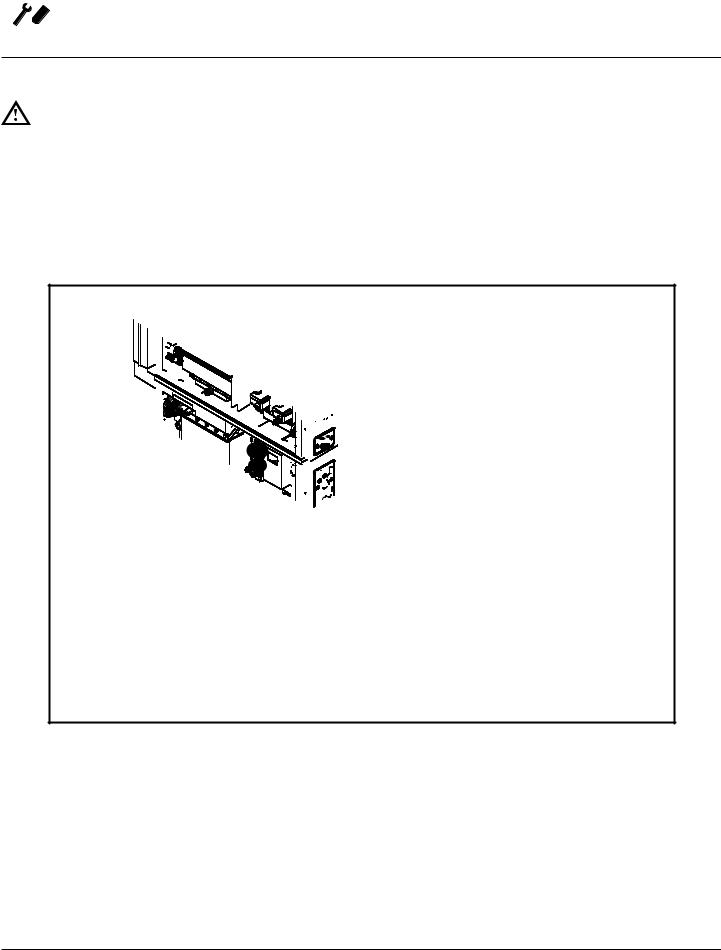
5.GAS APPLIANCES ONLY: Attach the flue vents and gas manifold as shown.
|
Steam Generator |
Hot Air Flue |
Flue (BCX-14 only) |
Left Side of Ovens
with Side Panels
Removed
Threaded Nut Retainer
Bolt
Gas Manifold
Rear View BCX-14G
Figure 4
8

Installation 
Deliming System Connection and Priming (BCX-14 units only)
DELIMING SYSTEM CONNECTION
1. Push deliming tube onto barbed fitting on oven back.
Figure 5
2.Cut deliming tube to length using the bottom of the deliming fluid reservoir in its mounted position as a guide. Install the jug weight on the deliming fluid reservoir end of the deliming tube.
3. Insert the end of the deliming tube with the jug weight into the deliming solution reservoir.
Figure 7
NOTE: If needed use supplied hose retainers and self drilling screws to route the deliming tube away from hot exhaust ports.
Figure 6
9

 Installation
Deliming System Connection and Priming (BCX-14 units only)
PRIME THE DELIMING PUMP
To prime the delime pump, use the following procedure for your oven control.
Standard Control
1.With the oven off, the display reads PRESS POWER
KEY TO TURN ON. Press the TOOLS key below the large knob. The tools menu is displayed.
2.Rotate the knob to highlight PRIME DELIME PUMP. Then press the right arrow key beneath the word OK.
3.If the Manager Passcode is enabled, enter 6647 on the passcode entry screen. Then press the right arrow key beneath the word OK.
4.In order to prime the delime pump, press the key below the word PUMP on the screen. When the word PUMP is highlighted the delime pump is pumping fluid from the bottle.
5.Watch for deliming solution to flow through the tube.
When the delime solution has reached the barbed fitting on the back of the oven, release the key below the word PUMP on the screen, and the pump will stop.
6.To return to the POWER screen, press the key below ESC on the screen above, then on the screen that follows.
Figure 8
10

Installation 
Deliming System Connection and Priming (BCX-14 units only)
SmartTouch 2™ Control
1.With the oven off, the control displays the POWER screen. Press the TOOLS key.
2.On the TOOLS MENU press the MANAGER key.
3.Press the PRIME DELIME PUMP key on the display.
4.Press and hold the PRIME key. Watch for deliming solution to flow through the tube. When the delime solution has reached the barbed fitting on the back of the oven, release the key.
5.The pump is now primed. Press the EXIT key.
6.Press the BACK key two times. The control returns to the POWER screen.
Figure 9
11
 Loading...