


BLODGETT CONVEYOR
STARTUP AND CALIBRATION GUIDE
BLODGETT OVEN COMPANY
www.blodgettcorp.com
50 Lakeside Avenue, Box 586, Burlington, Vermont 05402 USA Telephone (800) 331-5842, (802) 860-3700 Fax: (802)864-0183
PN M9437 Rev E (6/01)
E 2000 --- G.S. Blodgett Corporation

Table of Contents
Introduction
Pre-Startup Requirements . . . . . . . . . . . . . . . . . . . . . . . . . . . . . . . . . . . . . . . . . 2
Manual Control Startup
Control Identification . . . . . . . . . . . . . . . . . . . . . . . . . . . . . . . . . . . . . . . . . . . . . . 3
Gas Pressure Adjustments . . . . . . . . . . . . . . . . . . . . . . . . . . . . . . . . . . . . . . . . 4
Temperature Control Configuration . . . . . . . . . . . . . . . . . . . . . . . . . . . . . . . . . 5
Temperature Calibration . . . . . . . . . . . . . . . . . . . . . . . . . . . . . . . . . . . . . . . . . . . 6
Motor Control Board Adjustment . . . . . . . . . . . . . . . . . . . . . . . . . . . . . . . . . . . 7
Belt Speed Calibration . . . . . . . . . . . . . . . . . . . . . . . . . . . . . . . . . . . . . . . . . . . . 8
Closed Loop --- Dart Microdrive MDP . . . . . . . . . . . . . . . . . . . . . . . . . . . . 8
Open Loop . . . . . . . . . . . . . . . . . . . . . . . . . . . . . . . . . . . . . . . . . . . . . . . . . . . 9
Convection Blowers and Ventilation . . . . . . . . . . . . . . . . . . . . . . . . . . . . . . . . . 10
Computer Control Startup
Control Identification . . . . . . . . . . . . . . . . . . . . . . . . . . . . . . . . . . . . . . . . . . . . . . 11
Gas Pressure Adjustments . . . . . . . . . . . . . . . . . . . . . . . . . . . . . . . . . . . . . . . . 12
Convection Blowers . . . . . . . . . . . . . . . . . . . . . . . . . . . . . . . . . . . . . . . . . . . . . . 13
Computer Configuration . . . . . . . . . . . . . . . . . . . . . . . . . . . . . . . . . . . . . . . . . . 14
Temperature Calibration . . . . . . . . . . . . . . . . . . . . . . . . . . . . . . . . . . . . . . . . . . . 15
Belt Speed Calibration . . . . . . . . . . . . . . . . . . . . . . . . . . . . . . . . . . . . . . . . . . . . 16
Closed Loop Single Belt . . . . . . . . . . . . . . . . . . . . . . . . . . . . . . . . . . . . . . . 16
Open Loop Twin Belt . . . . . . . . . . . . . . . . . . . . . . . . . . . . . . . . . . . . . . . . . . 17
Ventilation . . . . . . . . . . . . . . . . . . . . . . . . . . . . . . . . . . . . . . . . . . . . . . . . . . . . . . . 17
Motor Control Board Adjustment . . . . . . . . . . . . . . . . . . . . . . . . . . . . . . . . . . . 18
PLC Control Startup
Control Identification and Registration . . . . . . . . . . . . . . . . . . . . . . . . . . . . . . 19
Gas Pressure Adjustments . . . . . . . . . . . . . . . . . . . . . . . . . . . . . . . . . . . . . . . . 20
Convection Blowers . . . . . . . . . . . . . . . . . . . . . . . . . . . . . . . . . . . . . . . . . . . . . . 23
Temperature Calibration . . . . . . . . . . . . . . . . . . . . . . . . . . . . . . . . . . . . . . . . . . . 24
Belt Speed Calibration . . . . . . . . . . . . . . . . . . . . . . . . . . . . . . . . . . . . . . . . . . . . 26

Introduction
Pre-Startup Requirements
OWNER’S RESPONSIBILITIES
A minimum of 5 to 7 working days are needed to schedule a start-up procedure.
Before a factory representative, or a factory trained representative, arrives to perform a startup procedure, the owner MUST ALREADY have satisfied the following requirements:
1.Gas Models: Installation of an adequate mechanically driven ventilation system for the unit. The ventilation system should replace 80% of the exhaust volume with fresh make up air. The table below can be used as a guideline.
2.Electric supplies installed by a certified professional.
NOTE: Refer to the Owner’s manual provided with the oven for electrical specifications.
3.Gas Models: Gas supplies installed by a certified professional.
NOTE: Refer to the Owner’s manual provided with the oven for gas specifications.
Be sure to size the meter for all gas models as follows:
U.S. installations
a.) Add the total BTU’s/hr of all the gas appliances on the line.
b.) Convert BTU’s to cubic ft/hr using the formula Cu Ft/Hr = 1000 BTU/Hr.
c.) Size the meter accordingly.
General export and Canadian installations
a.) Add the total M3/min of all the appliances on the line.
b.) Size the meter accordingly.
NOTE: Refer to the Owner’s manual provided with
the oven for additional information on utility installation requirements.
SERVICE AGENCY’S RESPONSIBILITIES
Before performing a start-up procedure, the service agency MUST ALREADY have satisfied the following requirements:
1.Assembly of the oven(s).
NOTE: Refer to the Owner’s manual provided with the oven for assembly.
2.Conversion of ovens to other types of gas when required.
Oven |
Exhaust Volume -- CFM (M3/min) |
Supply Requirements -- CFM (M3/min) |
|||||
Model |
|
|
|
|
|
|
|
Single |
Double |
Triple |
Single |
Double |
Triple |
||
|
|||||||
MT1828G |
400-500 |
800-1000 |
1200-1500 |
320-400 |
640-800 |
960-1200 |
|
|
(14-17) |
(23-28) |
(34-43) |
(12-14) |
(18-23) |
(27-34) |
|
SG2136G or |
400-500 |
800-1000 |
1200-1500 |
320-400 |
640-800 |
960-1200 |
|
MT2136G |
(14-17) |
(23-28) |
(34-43) |
(12-14) |
(18-23) |
(27-34) |
|
|
|
|
|
|
|
|
|
SG3240G or |
800-1000 |
1200-1600 |
2000-2400 |
640-800 |
960-1280 |
1600-1920 |
|
MT3240G |
(23-28) |
(34-46) |
(57-68) |
(18-23) |
(27-36) |
(46-54) |
|
|
|
|
|
|
|
|
|
MT3255G |
1000-1400 |
2000-2800 |
3000-4100 |
800-1120 |
1600-2240 |
2400-3300 |
|
|
(28-40) |
(57-79) |
(85-116) |
(23-32) |
(46-64) |
(68-93) |
|
MT3270 |
1200-1650 |
2400-3300 |
3600-5000 |
960-1320 |
1920-2640 |
2880-4000 |
|
|
(34-47) |
(68-93) |
(102-142) |
(27-37) |
(54-75) |
(82-113) |
|
MG3270 |
1200-1650 |
2400-3300 |
3600-5000 |
960-1320 |
1920-2640 |
2880-4000 |
|
|
(34-47) |
(68-93) |
(102-142) |
(27-37) |
(54-75) |
(82-113) |
|
MT3855 |
1000-1400 |
2400-3300 |
3600-5000 |
800-1120 |
1920-2640 |
2880-4000 |
|
|
(28-40) |
(68-93) |
(102-142) |
(23-32) |
(54-75) |
(82-113) |
|
|
|
|
|
|
|
|
|
MT3870 |
1200-1650 |
2400-3300 |
3600-5000 |
960-1320 |
1920-2640 |
2880-4000 |
|
|
(34-47) |
(68-93) |
(102-142) |
(27-37) |
(54-75) |
(82-113) |
|
2

Manual Control Startup
Control Identification
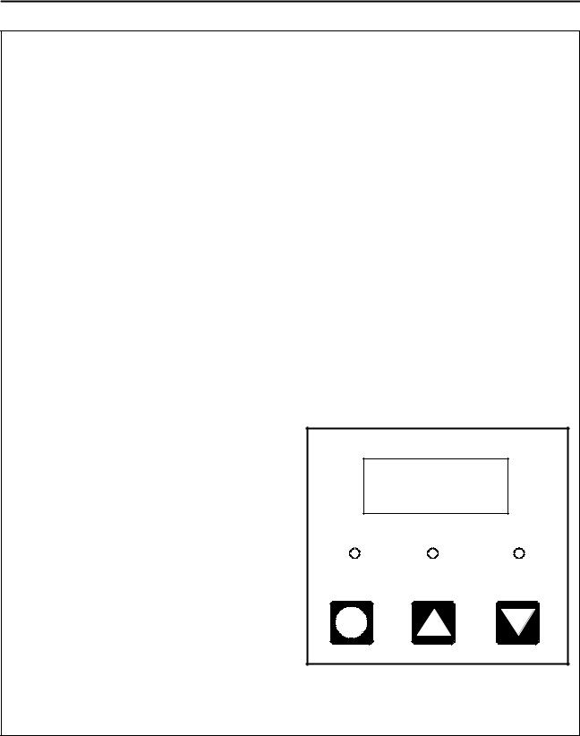
The following instructions are for the standard manual control. See Figure 1 for control identification.
COOK TIME
ON OFF
ACTUAL |
SETPOINT |
HEAT |
|
TEMPERATURE |
|
ON |
OFF |
ON |
OFF |
|
HEAT |
|
BLOWER |
CONVEYOR
Figure 1
3

Manual Control Startup
Gas Pressure Adjustments
THE FOLLOWING STARTUP PROCEDURES MUST BE PERFORMED BY A QUALIFIED TECHNICIAN
ONLY.
REGULATED GAS PRESSURE
NOTE: Gas models only.
Incoming static gas pressure to the unit, with all the gas appliances drawing from the supply, should be a minimum of 5.5” W.C. (13.7 mbar) for natural gas and 11” W.C. (28 mbar) for propane gas.
The manifold pressure, if measured after the regulator located inside the control box, must be 3.5” W.C. (9 mbar) for natural gas and 10” W.C. (25 mbar) for propane gas.
The pressure can be checked at the tap on either the dual regulated gas valve or the solenoid valve.
Turn the adjusting screw on the left front side of the dual regulated valve to adjust the gas pressure. Turn the screw clockwise to raise the gas pressure and counter-clockwise to lower it.
PRIMARY AIR ADJUSTMENT
NOTE: Gas models only.
The air shutter disc on the burner blower motor, located inside the control box at the top of the assembly, is factory adjusted to provide the most efficient blue flame possible at sea level.
1.Visually examine the quality of the flame.
2.If it needs adjusting, increase or decrease the air mixture to attain the best flame quality.
Regulator |
Cap |
Pressure Tap |
Regulator |
Adjustment |
Figure 2
4
Manual Control Startup
Temperature Control Configuration
CONFIGURATION PROCEDURES
NOTE: Follow these configuration procedures to change the factory settings.
To enter the Configuration Menus
1.Press and hold the actual temperature key for approximately 10 seconds. When the menu system has been accessed, the display toggles between dEF and either SP or Act.
Setting the Default Display
The default display determines whether the controller displays the actual or setpoint temperature.
1.Use the arrow keys to select the desired display default.
NOTE: We recommend using the setpoint display default.
2.Press the actual temperature key to enter the selected display default. The display toggles between HYS and a numerical value.
Setting the Control Hysteresis
The control hysteresis, or burner cycle is used to prevent rapid cycling around the setpoint. The hysteresis is adjustable from 2_F to 252_F (1_C to 122_C).
1.Use the arrow keys to select the desired control hysteresis.
NOTE: We recommend 5_F (3_C) initially.
2.Press the actual temperature key to enter the selected hysteresis value. The display toggles between OFF and a numerical value.
Setting the Display Offset
The display offset adjusts the displayed temperature if the actual temperature differs from the temperature seen by the thermocouple. If the actual temperature is lower a positive offset is needed. If the actual temperature is higher a negative offset is needed. The display offset is adjustable from -126_F to +126_F (-87_C to +52_C).
1.Use the arrow keys to select the desired display offset.
2.Press the actual temperature key to enter the selected offset value. The display toggles between ALr and a numerical value.
Setting the Deviation Band Alarm
The deviation band alarm causes the display to flash when the actual temperature varies (in either direction) from the setpoint. The deviation band alarm is adjustable to off or values from 1_F to 252_F (0.5_C to 122_C).
1.Use the arrow keys to select the desired deviation band alarm.
NOTE: We recommend 20_F (11_C).
2.Press the actual temperature key to enter the selected alarm value.
To exit the Configuration Menus
1.Push and hold the actual temperature key for approximately 3 seconds.
NOTE: The unit exits the configuration menus if
the controller is not touched for 1 minute at any time during programming.
SETTING THE DISPLAY UNITS
1.Press and hold the actual temperature key for approximately 10 seconds until the display reads unt and flashes F or c. Press the up or down arrow key to toggle between _F and _C.
2.Press and hold the actual temperature key until the control exits the programming mode.
ACTUAL |
SETPOINT |
HEAT |
Figure 3
5

Manual Control Startup
Temperature Calibration
Low Limit Adjustment
1.Bring the oven to 200_F (93_C).
2.Turn the blower and heat switches to OFF. The blower should continue to run.
3.Monitor the digital temperature control display. The blower motors should shut off within the range of 170-135_F(77-57_C).
4.To adjust the temperature, turn the low-limit potentiometer. A clockwise rotation increases the setting, counter-clockwise decreases it. See Figure 4.
High Limit Adjustment
NOTE: Refer to the wiring diagram shipped with the oven for terminal locations.
1.Remove the wires from the common and N.O. terminals. Touch the wires together to energize the heat circuit. This enables the oven to heat above the highest temperature allowed by the controller.
2.When the display reads 600_F (316_C), the burner blower motor should shut off. If the temperature rises above 600_F (316_C), adjust the hi-limit pot (Figure 4) so the burner shuts off at 600_F (316_C). A clockwise rotation of the high-limit pot increases the temperature, counter-clockwise decreases it.
|
|
|
|
|
|
|
|
P2 |
|
P1 |
|
|
P3 |
|
|
|
|
|
|
|
|
|
|
|
INCREASE |
INCREASE |
|
|
|
|
|
|
|||
|
|
|
|
|
|
|
|
|
|
|
|
|
|
9 T/C 10 |
|
|
|
|
|
|
|
|
|
|
|
|
|
|
|
|
RED |
+ |
|
|
|
DECREASE |
|
|
|
INCREASE |
DECREASE DECREASE |
|
|
|
|
|
|
||||||
|
|
|
LOW LIMIT |
HI LIMIT |
|
|
|
|
ACTUAL |
SETPOINT |
HEAT |
||||||
|
|
|
|
|
|
|
|
|
|
|
|||||||
|
|
|
|
|
|
|
|
T1 |
|
|
|
|
|
|
|||
|
|
|
|
|
|
|
|
|
|
|
|
|
|
|
|
|
|
INCREASE |
|
|
|
DECREASE |
|
|
|
|
|
|
|
|
|
|
|||
HI LIMIT |
|
|
|
LOW LIMIT |
|
|
|
|
|
|
|
|
|
|
|
||
|
|
|
|
|
|
|
|
ZYTRON |
|
|
|
|
|
|
|
|
|
|
|
|
|
|
|
|
SERIES 300 |
|
|
|
|
|
|
|
|
||
|
|
|
|
|
|
|
|
|
|
|
|
|
|
|
Athena Temperature Controller |
||
|
|
|
|
|
|
|
1 |
3 |
2 |
6 |
5 |
|
4 |
7 |
8 |
|
|
1 |
2 |
3 |
4 |
5 |
6 |
7 |
8 |
115 |
NO |
|
C |
NC |
NO |
C |
|
|
|
|
230 115 |
NC |
C |
NO |
NO |
C |
230 |
|
OUTPUT 1 |
OUTPUT 2 |
|
|
|||||
|
United Electric Board |
|
|
Zytron Board |
|
|
|
|
|||||||||
Figure 4
6

Manual Control Startup
Motor Control Board Adjustment
High/low speed motor control board adjustment for 180 and 130 VDC motors
NOTE: This procedure does not apply to Dart Microdrive systems or cooking computers.
NOTE: The motor control board is located on the slide out control panel.
High Speed Motor Adjustment:
1.Turn the cook time control knob on the front panel fully clockwise to decrease the cook time and turn the conveyor belt on.
2.With the motor connected (make no open circuit voltage readings) measure the voltage at the motor leads (A1 & A2 in Figure 5) on the DC control board. If the voltage is not within 3 VDC of the specified voltage continue with step 3.
3.Turn the MAX trim pot counter-clockwise to lower and clockwise to raise the voltage until it is within 3 VDC of the specified voltage.
Low Speed Motor Adjustment:
1.Turn the cook time control knob on the front panel fully counter-clockwise to increase the cook time.
2.With the motor connected (make no open circuit voltage readings) measure the voltage at the motor leads on the DC control board (A1 & A2 in Figure 5). If the voltage is not within 1 VDC of the specified voltage, continue with step 3.
3.Turn the MIN SPEED pot clockwise to lower the voltage and counter-clockwise to raise the voltage.
|
130 Volt System |
180 Volt System |
||||
Model |
Low |
|
High |
Low |
|
High |
|
|
|||||
|
|
|
|
|
|
|
MT2136 |
20 |
|
130 |
26 |
|
180 |
|
|
|
|
|
|
|
MT3255 |
26 |
|
130 |
26 |
|
180 |
|
|
|
|
|
|
|
MT3270 |
26 |
|
130 |
26 |
|
180 |
|
|
|
|
|
|
|
MG3270 |
26 |
|
130 |
N/A |
|
N/A |
|
|
|
|
|
|
|
|
|
|
Minimum Speed Pot |
|
|
|
|
|||
|
|
|
|
|
||||
|
|
|
Torque (current) limiting adjustment |
|||||
|
|
|
|
|
|
|
|
|
Maximum Speed Pot |
|
|
|
|
|
|
(DO NOT ADJUST) |
|
|
|
|
|
|||||
|
|
|
|
|
|
|
|
|
|
|
Yellow or Violet (pin 12) |
ACC |
MAX |
MIN |
TORQ |
ON |
|
|
Orange or Gray (pin 10) |
|
|
TP1 |
|
|
|
|
|
|
|
|
|
|
|
|
Blue (pin 8) |
|
|
TP2 |
|
|
Violet |
Gray |
|
J1 |
|
|
|
REG |
Blue |
|
|
|
|
|||
|
|
|
|
|
|||
|
|
|
FL |
|
|
|
|
|
|
|
TB1 |
|
|
|
|
|
Speed Pot |
L |
N |
A1 |
A2 |
FA |
|
|
|
||||||
Line Hot (VAC) |
+ |
Barrier Terminal Block TB1 |
|
||
Line Neutral (VAC) |
- |
Power Line and Motor Ground |
|
PM Motor Armature |
|
REMOVE RED PLUG FROM TOP OF DC MOTOR PRIOR TO OPERATING!
Warning: Circuit components are not at ground potential! Use only a non-metallic or insulated adjustment tool. Shock hazards may occur with conducting tools!
Figure 5
7
Manual Control Startup
Belt Speed Calibration
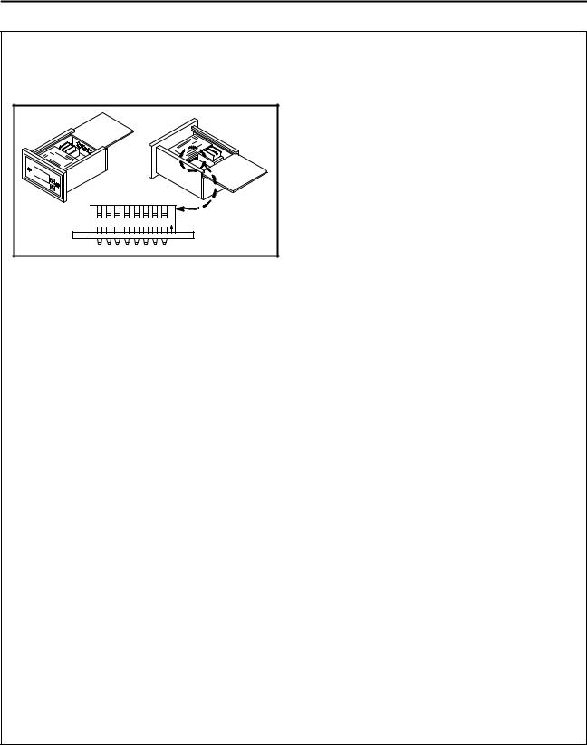
CLOSED LOOP -- DART MICRODRIVE MDP
1.Remove the top cover. The internal dip switch is located next to the transformer.
Dip Switch Detail |
|||||||
|
|
|
|
|
|
|
O |
1 |
2 |
3 |
4 |
5 |
6 |
7 |
8 N |
Figure 6
PROGRAMMING THE MDP CONTROL
NOTE: Any variable can be changed WITHOUT resetting the others.
To Enter the Program Mode
1.Set DIP switches 1, 2, 3, 4, 5, 6 and 8 to OFF. Set DIP switch 7 to ON. The motor stops.
2.The display reads PROG.
NOTE: In rate mode the current decimal point is also displayed.
Time or Rate Mode (Displayed Decimal Place)
This allows settings to be made in the proper units.
1.Set DIP switch 4 to ON.
2.The current decimal point (if any) will be lit. The display gives the current value of the decimal place variable. To change press the up or down arrow keys. Use 0-4 for the rate mode. Use 5 for the time mode.
NOTE: The decimal point will not be lit if the unit is currently in the time mode.
3.When finished, flip DIP switch 4 to OFF.
4.The display reads PROG.
K Constant
1.Flip DIP switch 1 to ON.
2.The display gives the current value for the constant. To change press the up or down arrow keys.
NOTE: For ovens with a 70” (178 cm) tunnel the preset constant is 5:20. For ovens
with a 55” (140 cm) tunnel the preset constant is 4:08.
3.When finished, set DIP switch 1 to OFF.
4.The display reads PROG.
NOTE: If you change the constant, the display set-
ting will be set to the slowest speed when you exit the programming mode.
Minimum Setting
1.Flip DIP switch 2 to ON.
2.The display gives the current value for the lower limit. To change press the up or down arrow keys.
3.When finished flip DIP switch 2 to OFF.
4.The display reads PROG.
Maximum Setting
1.Flip DIP switch 3 to ON.
2.The display gives the current value for the upper limit. To change press the up or down arrow keys.
3.When finished flip DIP switch 3 to OFF.
4.The display reads PROG.
To Exit the Program Mode
1.Make sure DIP switch 5 (Master/Follower Mode select) is in the desired position
(ON = Follower; OFF= Master).
NOTE: In most cases DIP switch 5 should be set to the master position (OFF).
2.Set DIP switches 1, 2, 3, 4, 6 and 8 to OFF.
3.If satisfied with programming values, set DIP switch 7 to OFF. The control operates using the new programmed variables.
CHECKING THE BELT SPEED CALIBRATION
Place a pan on the belt and start the conveyor.
1.Begin timing the belt’s speed when the trailing edge of the pan enters the oven.
2.End the timing cycle when the trailing edge of the pan exits the oven.
3.If the displayed time differs from the actual more than 5 seconds, reprogram the K constant.
8
 Loading...