


Blodgett BLCT62102G, BLCT6262G, BLCT61101G, BLCT6161G, BLCT102G User Manual
...
BCT & BLCT
COMBI OVENS
INSTALLATION - OPERATION - MAINTENANCE
BLODGETT OVEN COMPANY
www.blodgett.com
44 Lakeside Avenue, Burlington, Vermont 05401 USA Telephone: (802) 658-6600 Fax: (802)864-0183
PN 61041 Rev J (11/15)
© 2015 - G.S. Blodgett Corporation

Your Service Agency’s Address:
Model
Serial number
Oven installed by
Installation checked by

IMPORTANT
WARNING: Improper installation, adjustment, alternation, service or maintenance can cause property damage, injury or death. Read the instllation, operation and maintenance instructions thoroughly before installing or servicing this equipment.
INSTRUCTIONS TO BE FOLLOWED IN THE EVENT THE USER SMELLS GAS MUST BE POSTED IN A PROMINENT LOCATION. This information may be obtained by contacting your local gas supplier.
FOR YOUR SAFETY
Do not store or use gasoline or other flammable vapors or liquids in the vicinity of this or any other appliance.
The information contained in this manual is important for the proper installation, use, and maintenance of this oven. Adherence to these procedures and instructions will result in satisfactory baking results and long, trouble free service. Please read this manual carefully and retain it for future reference.
ERRORS: Descriptive, typographic or pictorial errors are subject to correction. Specifications are subject to change without notice.
TABLE OF CONTENTS
INSTALLATION
Utility Connections - Standards and Codes.. . . . . . . . . . . . . . . . . . . . . . . . . . . . . . . . . 2 The Blodgett Combi-Oven/Steamer.. . . . . . . . . . . . . . . . . . . . . . . . . . . . . . . . . . . . . . . . 3 Description of the Combi-Oven/Steamer. . . . . . . . . . . . . . . . . . . . . . . . . . . . . . . . . . . . 4 Utility Specifications.. . . . . . . . . . . . . . . . . . . . . . . . . . . . . . . . . . . . . . . . . . . . . . . . . . . . . . 5 Oven Assembly to Stand. . . . . . . . . . . . . . . . . . . . . . . . . . . . . . . . . . . . . . . . . . . . . . . . . . 6 Oven Location and Leveling. . . . . . . . . . . . . . . . . . . . . . . . . . . . . . . . . . . . . . . . . . . . . . . 7 Plumbing Connections. . . . . . . . . . . . . . . . . . . . . . . . . . . . . . . . . . . . . . . . . . . . . . . . . . . . 8 Electrical Connection and Ventilation. . . . . . . . . . . . . . . . . . . . . . . . . . . . . . . . . . . . . . 10 Gas Connection. . . . . . . . . . . . . . . . . . . . . . . . . . . . . . . . . . . . . . . . . . . . . . . . . . . . . . . . . 11 Gas Hose Restraint.. . . . . . . . . . . . . . . . . . . . . . . . . . . . . . . . . . . . . . . . . . . . . . . . . . . . . 13 Final Check Lists. . . . . . . . . . . . . . . . . . . . . . . . . . . . . . . . . . . . . . . . . . . . . . . . . . . . . . . . 14
OPERATION
Safety Information for Gas Ovens. . . . . . . . . . . . . . . . . . . . . . . . . . . . . . . . . . . . . . . . . 15 BCT Touchscreen Control Description. . . . . . . . . . . . . . . . . . . . . . . . . . . . . . . . . . . . . 16 Main Menu.. . . . . . . . . . . . . . . . . . . . . . . . . . . . . . . . . . . . . . . . . . . . . . . . . . . . . . . . . . . . . 17 Hot Air Mode. . . . . . . . . . . . . . . . . . . . . . . . . . . . . . . . . . . . . . . . . . . . . . . . . . . . . . . . . . . . 18 Steam Mode. . . . . . . . . . . . . . . . . . . . . . . . . . . . . . . . . . . . . . . . . . . . . . . . . . . . . . . . . . . . 20 Retherm Mode. . . . . . . . . . . . . . . . . . . . . . . . . . . . . . . . . . . . . . . . . . . . . . . . . . . . . . . . . . 21 CombiSmart Mode.. . . . . . . . . . . . . . . . . . . . . . . . . . . . . . . . . . . . . . . . . . . . . . . . . . . . . . 22 CombiOptima Mode.. . . . . . . . . . . . . . . . . . . . . . . . . . . . . . . . . . . . . . . . . . . . . . . . . . . . . 23 Using the Core Probe. . . . . . . . . . . . . . . . . . . . . . . . . . . . . . . . . . . . . . . . . . . . . . . . . . . . 24 SmartChef Automatic Cooking. . . . . . . . . . . . . . . . . . . . . . . . . . . . . . . . . . . . . . . . . . . . 26 Using Rack Timing.. . . . . . . . . . . . . . . . . . . . . . . . . . . . . . . . . . . . . . . . . . . . . . . . . . . . . . 28 Using Advanced Rack Timing.. . . . . . . . . . . . . . . . . . . . . . . . . . . . . . . . . . . . . . . . . . . . 29 PreHeat, Cool Down and Proofing.. . . . . . . . . . . . . . . . . . . . . . . . . . . . . . . . . . . . . . . . 32 Cook to Perfection.. . . . . . . . . . . . . . . . . . . . . . . . . . . . . . . . . . . . . . . . . . . . . . . . . . . . . . 34 Programmed Cooking.. . . . . . . . . . . . . . . . . . . . . . . . . . . . . . . . . . . . . . . . . . . . . . . . . . . 35 Adding a New Recipe Program.. . . . . . . . . . . . . . . . . . . . . . . . . . . . . . . . . . . . . . . . . . . 36 Favorites.. . . . . . . . . . . . . . . . . . . . . . . . . . . . . . . . . . . . . . . . . . . . . . . . . . . . . . . . . . . . . . . 37 USB.. . . . . . . . . . . . . . . . . . . . . . . . . . . . . . . . . . . . . . . . . . . . . . . . . . . . . . . . . . . . . . . . . . . 38 Timed Start.. . . . . . . . . . . . . . . . . . . . . . . . . . . . . . . . . . . . . . . . . . . . . . . . . . . . . . . . . . . . . 40 HACCP Library.. . . . . . . . . . . . . . . . . . . . . . . . . . . . . . . . . . . . . . . . . . . . . . . . . . . . . . . . . 41
MAINTENANCE
Cleaning & Preventative Maintenance. . . . . . . . . . . . . . . . . . . . . . . . . . . . . . . . . . . . . 42 Deliming - BCT only.. . . . . . . . . . . . . . . . . . . . . . . . . . . . . . . . . . . . . . . . . . . . . . . . . . . . . 44

 Installation
Utility Connections - Standards and Codes
THE INSTALLATION INSTRUCTIONS CONTAINED HEREIN ARE FOR THE USE OF QUALIFIED INSTALLATION AND SERVICE PERSONNEL ONLY. INSTALLATION OR SERVICE BY OTHER THAN QUALIFIED PERSONNEL MAY RESULT IN DAMAGE TO THE OVEN AND/OR INJURY TO THE OPERATOR.
Qualified installation personnel are individuals, a firm, a corporation, or a company which either in person or through a representative are engaged in, and responsible for:
•the installation or replacement of gas piping and the connection, installation, repair or servicing of equipment.
•the installation of electrical wiring from the electric meter, main control box or service outlet to the electric appliance.
Qualified installation personnel must be experienced in such work, familiar with all precautions required, and have complied with all requirements of state or local authorities having jurisdiction.
U.S. and Canadian installations
The installation must conform with local codes, or in the absence of local codes, with the National Fuel Gas Code, ANSI Z223.1/NFPA 54, or the Natural Gas and Propane Installation Code, CSA B149.1, as applicable.
Installation must conform with local codes, or in the absence of local codes, with the National Electrical Code, ANSI/NFPA 70-Latest Edition and/or Canadian National Electric Code C22.1 as applicable.
Appliance is to be installed with backflow prevention in accordance with applicable federal, province and local codes.
Australia and general export installations
Instllation must conform with Local and National installation standards. Local installation codes and/or requirements may vary. If you have any questions regarding the proper installation and/or operation of your Blodgett oven, please contact your local distributor. If you do not have a local distributor, please call the Blodgett Oven Company at 0011-802-658-6600.
2

Installation 
The Blodgett Combi-Oven/Steamer offers a completely new method of cooking. With the Oven/Steamer you have the choice of two cooking processes: Steam and Hot Air, either...
•Separately
•Combined, or
•In Sequence
And for easy operation you can choose from three modes: In the Steam mode you can:
steam |
reheat |
reconstitute |
stew |
thaw |
simmer |
blanche |
preserve |
braise |
poach |
|
|
In the Hot Air mode you can: |
|
|
roast |
bake |
grill |
gratinate |
broil |
|
In the Combination Steam and Hot Air mode you can:
defrost |
roast |
rethermalize |
reheat |
bake |
forced steam |
There are four additional specialized modes to help you make the most of your time:
Retherm - for perfect reheating
Proofing - Proof and bake all in the same oven
Preheat - in this mode the oven will preheat to 575ºF (300ºC) for 15 minutes. The oven will then automatically lower to 480ºF (249ºC) to protect the advanced electronic components.
Cool Down - allows the oven cavity to cool down rapidly with the door opened
The Blodgett Combi-Oven/Steamer
You can also use two or three functions in sequence during one cooking process. We call this:
•combi-steaming
•combi-roasting
•combi-baking
The combination of circulating hot air and steam in the space saving, high performance Combi-Oven/Steamer leads to improvements in the following areas:
•increased productivity in the kitchen
•a reduction in capital expenditures for multiple equipment replacement
•a wider range of menu choices
•a simplified cleaning process
The work process is simplified since products are prepared on or in steam table pans and trays. Food can be cooked, stored, and transported with the same pans.
Small amounts of product can be processed efficiently; pre-cooked and convenience foods can be reheated within minutes. Many frozen foods can be processed without pre-thawing. This flexibility in preparation reduces the need for kettles and steam tables since there is no need for large amounts of food to be kept warm for long periods of time.
Today the improvement of food quality is more important than ever. Vegetables are cooked in the Blodgett CombiOven/Steamer without water at the optimal temperature of just under 212ºF (100ºC), maintaining valuable vitamins, minerals, nutrients and trace elements. Cooking meat in the Combi results in less shrinkage and a firmer, juicier product. The Blodgett Combi-Oven/Steamer is being used more and more for baking. Steam and Hot Air modes make it a general purpose baking appliance.
3

 Installation
Description of the Combi-Oven/Steamer
ABOUT THE OVEN/STEAMER
Blodgett Combis are quality produced using high-grade stainless steel with first class workmanship.
The multiple speed fan, which is guarded against accidental finger contact, is driven by a quiet and powerful motor. The condenser draws out excess steam from the appliance. Condensation and waste water, which result during steaming and cleaning, are continuously drained.
The use of high quality insulation impedes excessive heat radiation and saves energy.
Fresh steam enters the oven cavity without pressure and circulates at high speed. This process enables quick and gentle cooking and ensures high quality food while pro-
viding convenient working methods. The steam generator is completely automatic and protected from running dry.
OVEN/STEAMER OPERATION
The practical oven door, with a viewing window, has a wide swing radius and handle which can be operated easily, even with wet or greasy hands.
Ease of operation is guaranteed through the simple to use control. With graphical symbols and storage for 50 product recipes the BCT/BLCT is easy for even inexperienced kitchen staff to operate.
Cleaning is kept to a minimum thanks to the automatic Combi Wash system.
|
PLUMBING SPECIFICATIONS |
WATER |
|
Water pressure |
36.26 PSI (250 kPa, 2.5 bar) during Combi Wash |
|
21.76 PSI (150 kPa, 1.5 bar) when Combi Wash is not active |
|
40(min)-50(max) PSI supply pressure |
Water connection |
3/4” garden hose cold water |
Water quality requirements |
TDS: 40-125 ppm |
|
Hardness: 35-100 ppm |
|
Chlorides: <25 ppm |
|
Silica: <13 ppm |
|
Chlorine: < 0.2 ppm |
|
Chloramine: < 0.2 ppm |
|
pH: 7.0-8.5 |
DRAINAGE |
|
Drain type |
Atmospheric Vented Drain |
Drain connection |
2.00” (50.8mm) Copper |
|
1.57” (40mm) Copper - mini combi ovens |
Maximum water drain temperature |
140ºF (60ºC) |
RATINGS - GAS OVENS
Model |
Gas Type |
Input |
Voltage |
Phase |
Amps |
BLCT-61G |
Natural |
58,000 BTU |
115 |
1 |
9 |
|
Propane |
58,000 BTU |
115 |
1 |
9 |
BLCT-101G |
Natural |
87,000 BTU |
115 |
1 |
9 |
|
Propane |
87,000 BTU |
115 |
1 |
9 |
BLCT-102G |
Natural |
95,500 BTU |
115 |
1 |
9 |
|
Propane |
95,500 BTU |
115 |
1 |
9 |
BLCT-62G |
Natural |
81,800 BTU |
115 |
1 |
9 |
|
Propane |
81,800 BTU |
115 |
1 |
9 |
BLCT-202G |
Natural |
190,000 BTU |
115 |
1 |
17 |
|
Propane |
190,000 BTU |
115 |
1 |
17 |
4

Installation 
Utility Specifications
ELECTRICAL RATINGS
Model |
Voltage |
kW |
Hz |
Phase |
Max Load (amps) |
|
|
|
2.7/3.3/3.6 |
50/60 |
1NAC |
15 |
|
|
208/230/240 |
2.7/3.3/3.6 |
50/60 |
2AC |
15 |
|
BLCT-23E |
|
5.4/6.6/7.2 |
50/60 |
3AC |
30 |
|
Mini Combi |
400/415 |
6.6/7.2 |
50/60 |
2NAC |
15 |
|
|
5.4/5.8 |
50/60 |
2AC |
15 |
||
|
|
|||||
|
440/480 |
5.4/6.5 |
50/60 |
2AC |
15 |
|
|
208 |
4.6 |
50/60 |
1 |
23 |
|
BLCT-6E |
240 |
6.1 |
50/60 |
1 |
26 |
|
Mini Combi |
208 |
6.9 |
50/60 |
3 |
20 |
|
|
240 |
9.2 |
50/60 |
3 |
23 |
|
|
208/230/240 |
10.4/12.7/13.8 |
50/60 |
3AC |
34 |
|
BLCT-10E |
10.4/12.7/13.8 |
50/60 |
3NAC |
34 |
||
|
||||||
|
12.7/13.8 |
50/60 |
3NAC |
20 |
||
Mini Combi |
400/415 |
|||||
12.7/13.8 |
50/60 |
3AC |
20 |
|||
|
|
|||||
|
440/480 |
10.4/12.4 |
50/60 |
3AC |
18 |
|
BCT-61E |
208 |
9 |
60 |
3 |
25 |
|
240 |
9 |
60 |
3 |
22 |
||
BLCT-61E |
||||||
480 |
9 |
60 |
3 |
11 |
||
|
||||||
BCT-101E |
208 |
18 |
60 |
3 |
50 |
|
240 |
18 |
60 |
3 |
44 |
||
BLCT-101E |
||||||
480 |
18 |
60 |
3 |
22 |
||
|
||||||
BCT-102E |
208 |
27 |
60 |
3 |
75 |
|
240 |
27 |
60 |
3 |
65 |
||
BLCT-102E |
||||||
480 |
27 |
60 |
3 |
33 |
||
|
||||||
BCT-62E |
208 |
21 |
60 |
3 |
59 |
|
240 |
21 |
60 |
3 |
51 |
||
BLCT-62E |
||||||
480 |
21 |
60 |
3 |
26 |
||
|
||||||
BCT-202E |
208 |
60 |
60 |
3 |
167 |
|
240 |
60 |
60 |
3 |
145 |
||
BLCT-202E |
||||||
480 |
60 |
60 |
3 |
73 |
||
|
5
 Installation
Oven Assembly to Stand
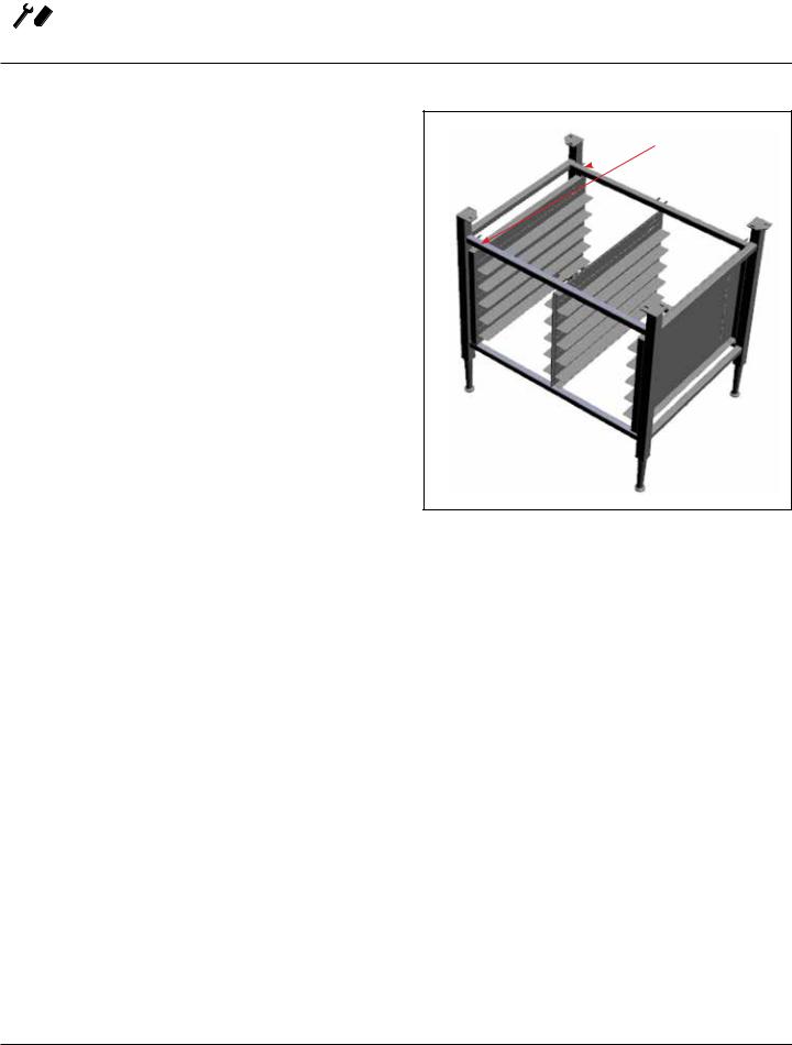
Your Blodgett COMBI oven has been shipped with black plastic caps on the corners of its base. In order to mount your oven to its stand, please do the following:
1.Remove the stand from the packaging. Install the casters or feet into the base of the stand. If inserting casters ensure that the locking casters are at the front of the stand, see figure. Place the stand upright in an area readily available.
2.Remove all packaging from the oven, so that the oven can be picked up.
3.Remove the black plastic caps on each corner by removing the two screws holding them on. Do NOT discard these screws; they will be used to mount the oven to the stand.
4.Position the oven over the stand and align the corner brackets on the stand with the holes on the oven.
5.Use the screws from the plastics caps to mount the oven to the stand.
6.The oven has now been properly fastened to the stand.
Note difference in rail  placement
Front of stand
Figure 1
6
Installation 
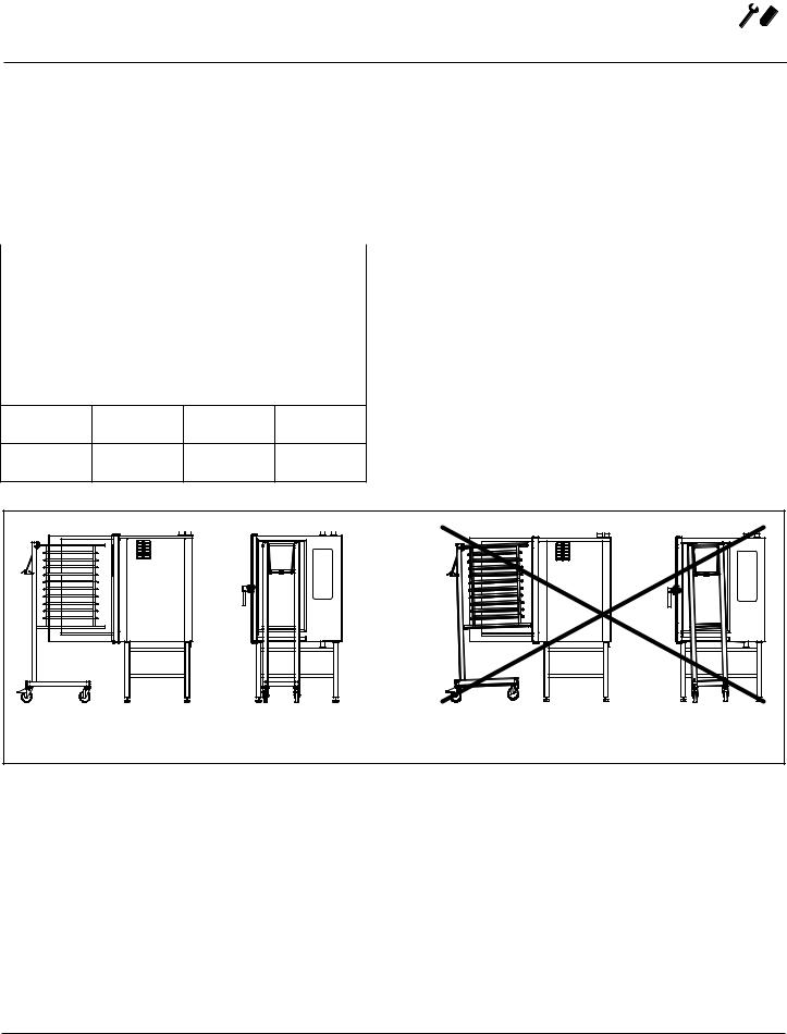
Oven Location and Leveling
The well planned and proper placement of your oven will result in long term operator convenience and satisfactory performance.
Certain minimum clearances must be maintained between the oven and any combustible or non-combustible construction.
Strong sources of heat such as hotplates, tilting frying pans, deep fat fryers, etc. should not be placed near the oven, especially near its right side. An optional side heat shield is available.
In addition, the following clearances are recommended for servicing.
|
|
|
|
|
• Oven body sides - 12” (30cm) |
|
|
|
|
|
|
||
MINIMUM REQUIRED CLEARANCES |
• Oven body back - 12” (30cm) |
|||||
Size |
|
Left |
Right |
Back |
To ensure that the oven functions correctly when installed, |
|
Electric Ovens |
|
|
|
|||
|
|
|
it should be placed upright and level (horizontally). This is |
|||
61, 101, |
|
2.75” |
2.75” |
2” |
measured at the front and side edge of the roof. The oven |
|
102 & 202 |
|
(70mm) |
(70mm) |
(50mm) |
can be levelled using the adjusting screws on the stand or |
|
62 |
|
0” |
4” |
2” |
on the legs of table models. The height of the oven should |
|
|
|
(0mm) |
(102mm) |
(50mm) |
also be adjusted to fit the trolley for rack. |
|
Gas Ovens
61, 101, |
2.75” |
2.75” |
2” |
102 & 202 |
(70mm) |
(70mm) |
(50mm) |
62 |
0” |
4” |
2” |
|
(0mm) |
(102mm) |
(50mm) |
|
Correct Installation |
Incorrect Installation |
|
Figure 2
7
 Installation
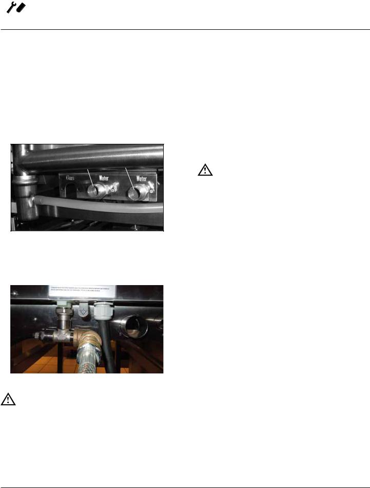
Plumbing Connections
WATER CONNECTION
Blodgett BCT/BLCT ovens have two water connections. Both are located at the back of the unit.
BCT/BLCT-61, 62, 101, 102 and 202 models
•1 connection for raw water for the condensation jet.
•1 connection for steam generation and the Combi Wash jet in the oven chamber. Must meet the requirements applying to water supplied to household appliances.
Quench Steam
Figure 3
BLCT-23, 6 and 10 Mini Combi models
•1 water connection. Must meet the requirements applying to water supplied to household appliances.
To facilitate cleaning and servicing, the oven should be connected with an approved flexible 3/4” hose. Permanent installations should be fitted with a stop-tap and a non-return valve.
Before connecting the oven to water, flush the tubes thoroughly. Connect the oven.
DRAIN CONNECTION
Blodgett ovens are equipped with a drain system that removes surplus water from the oven chamber. This may be condensed water from the products, or it may occur when the oven chamber is cooled down with cold water, or when the oven chamber is cleaned.
WARNING!!
Connection must be carried out by an authorised plumber, to an open or closed drain. The drain must never end directly beneath the oven.
The drain must be of stainless steel or an equally temperature-resistant material, have a fall of at least 3° or 5%. See page 4 for drain diameter.
 Water
Water
connection
Figure 4
WARNING!!
If the water temperature exceeds 70°F (21°C), problems with regard to Combi Optima calibration and cooling of the oven may occur.
The water connection must be carried out by an authorized plumber in accordance with existing local codes.
Clogged up water filters and dirt in the solenoid valves are not covered by the warranty.
8
Installation 
CLEANING & DELIMING CHEMICAL
1.BCT/BLCT-61, 62, 101, 102 and 202 ovens only. The oven is supplied with a chemical bottle holder. The holder can be affixed to either side of the oven. Place it on the stand crossmember.
Figure 5
2.Connect the supplied detergent tubes (red and blue) to the underside of the oven near the rear. Connect the blue hose to the fitting with the blue sticker and the red hose to the fitting with the red sticker.
Blue Sticker
Red Sticker
Red Tube |
Blue Tube |
Plumbing Connections
3.Insert the blue and red hoses into the proper bottles. Red is for detergent, blue is for rinse aid.
4.BCT only - The last line is for the delimer. This is the tan colored tube protroding from the bottom of the oven. Cut the tubing to the proper length, if needed, and place the tubing into the delime bottle.
NOTE: If the tube is cut to length, remove the stainless steel weight from the end of the tube and reinsert.
Figure 6
9
 Installation
Electrical Connection and Ventilation
ELECTRICAL CONNECTION
NOTE: Electrical connections must be performed by a qualified installer only.
Before making any electrical connections to these appliances, check that the power supply is adequate for the voltage, amperage, and phase requirements stated on the rating name plate mounted on the appliance.
1.The rating plate is located on the right side of the oven.
An approved plug outlet or a safety cutout must be located close to the oven so that the oven can be disconnected during installation and repair. The safety cutout must be able to cut off all poles with a total distance of break of at least 3 mm.
All appliances must be installed in accordance with Local or National Electrical codes.
The wiring diagram is located in the motor compartment.
NOTE: Disconnect the power supply to the appliance before servicing.
WARNING!!
Improper installation may invalidate your warranty.
Electric Models
A strain relief for the power supply cord is provided. The installer must supply a cord that meets all Local and National installation standards.
Gas Models
U.S. and Canadian Installations
A power cord (115V units only) is supplied with a plug attached. Plug the power cord into the desired receptacle.
NOTE: The BLCT-202G must be hard wired.
This oven model uses a variable frequency inverter drive. Appliances that use variable frequency inverter drives produce high frequency noise and require filters and shielded motor cabling. This causes higher leakage current toward Earth Ground. Especially, at the moment of switching ON this can cause an inadvertent trip of the appliance’s ground fault interrupter (GFCI). Some GFCIs are more sensitive than others. Blodgett has qualified the
Pass and Seymour brand, part number 2095, 20 A, 125
VAC, 60 Hz, specification grade GFCI duplex receptacle as being immune to the variable frequency inverter drive’s noise. Blodgett recommends using this specific GFCI for this model oven.
WARNING!!
If the supply cord is damaged, it must be replaced by a special cord or assembly available from the manufacturer or its service agent.
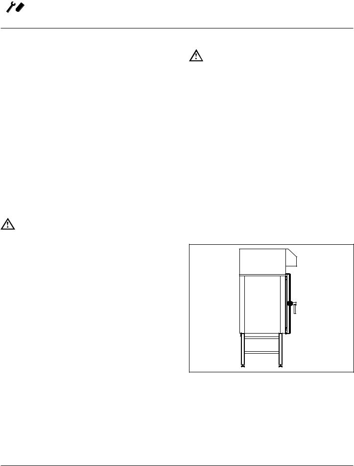
VENTILATION
Blodgett BCT/BLCT ovens are equipped with an open/direct exhaust system that removes surplus humidity from the oven chamber. The exhaust system has an electrically operated damper.
The ventilation motor can be controlled directly from the oven. This means that the ventilation starts when a program is started and runs for 10 minutes after the program is completed.
BCT/BLCT-61, 62, 101, 102 and 202 ovens only. The exhaust tube can be connected to a ventilation system. In that case, a special extraction funnel is fitted to avoid suction directly from the oven chamber. This extraction funnel can be ordered from Blodgett.
If an extraction hood is installed in the ceiling above the oven, it should project 20” (50 cm) over the front of the oven.
Figure 7
10

Installation 
GAS PIPING
A properly sized gas supply system is essential for maximum oven performance. Piping should be sized to provide a supply of gas sufficient to meet the maximum demand of all appliances on the line without loss of pressure at the equipment.
Example:
NOTE: BTU values in the following example are for natural gas.
You purchase a BLCT-61G to add to your existing cook line.
1. Add the BTU rating of your current appliances.
Pitco Fryer |
120,000 BTU |
6 Burner Range |
60,000 BTU |
Deck Oven |
50,000 BTU |
Total |
230,000 BTU |
2. Add the BTU rating of the new oven to the total.
Previous Total |
230,000 BTU |
BLCT-61G |
40,900 BTU |
New Total |
270,900 BTU |
3.Measure the distance from the gas meter to the cook line. This is the pipe length. Let’s say the pipe length is 40’ (12.2 m) and the pipe size is 1” (2.54 cm).
4.Use the appropriate table to determine the total capacity of your current gas piping.
The total capacity for this example is 375,00 BTU. Since the total required gas pressure, 270,900 BTU is less than
375,000 BTU, the current gas piping will not have to be increased.
NOTE: The BTU capacities given in the tables are for straight pipe lengths only. Any elbows or other fittings will decrease pipe capacities. Contact your local gas supplier if you have any questions.
Gas Connection
Maximum Capacity of Iron Pipe in Cubic Feet of
Natural Gas Per Hour
(Pressure drop of 0.5 Inch W.C.)
PIPE |
|
NOMINAL SIZE, INCHES |
|
||||
LENGTH (FT) |
3/4” |
|
1” |
1-1/4” |
1-1/2” |
|
2” |
10 |
360 |
|
680 |
1400 |
2100 |
|
3950 |
20 |
250 |
|
465 |
950 |
1460 |
|
2750 |
30 |
200 |
|
375 |
770 |
1180 |
|
2200 |
40 |
170 |
|
320 |
660 |
990 |
|
1900 |
50 |
151 |
|
285 |
580 |
900 |
|
1680 |
60 |
138 |
|
260 |
530 |
810 |
|
1520 |
70 |
125 |
|
240 |
490 |
750 |
|
1400 |
80 |
118 |
|
220 |
460 |
690 |
|
1300 |
90 |
110 |
|
205 |
430 |
650 |
|
1220 |
100 |
103 |
|
195 |
400 |
620 |
|
1150 |
From the National Fuel Gas Code Part 10 Table 10-2
Maximum Capacity of Pipe in Thousands of BTU/hr of Undiluted L.P. Gas at 11” W.C.
(Pressure drop of 0.5 Inch W.C.)
PIPE |
OUTSIDE DIAMETER, INCHES |
||
LENGTH (FT) |
3/4” |
1” |
1-1/2” |
10 |
608 |
1146 |
3525 |
20 |
418 |
788 |
2423 |
30 |
336 |
632 |
1946 |
40 |
287 |
541 |
1665 |
50 |
255 |
480 |
1476 |
60 |
231 |
435 |
1337 |
70 |
215 |
404 |
1241 |
80 |
198 |
372 |
1144 |
90 |
187 |
351 |
1079 |
100 |
175 |
330 |
1014 |
From the National Fuel Gas Code Part 10 Table 10-15
11

 Installation
Gas Connection
PRESSURE REGULATION AND TESTING
The gas pressure to the appliance must be rated for each appliance while the burners are on. A sufficient gas pressure must be present at the inlet to satisfy these conditions. Refer to the table below for correct gas pressure.
Each appliance has been adjusted at the factory to operate with the type of gas specified on the rating plate.
Each oven is supplied with a regulator to maintain the proper gas pressure. The regulator is essential to the proper operation of the oven and should not be removed.
DO NOT INSTALL AN ADDITIONAL REGULATOR WHERE THE UNIT CONNECTS TO THE GAS SUPPLY UNLESS THE INLET PRESSURE IS GREATER THAN 14” W.C. (1/2 PSI) (37mbar).
The oven and its individual shutoff valve must be disconnected from the gas supply piping system during any pressure testing of that system at test pressures in excess of 1/2 psig (3.45kPa).
The oven must be isolated from the gas supply piping system by closing its individual manual shutoff valve during any pressure testing of the gas piping system at test pressures equal or less than 1/2 psig (3.45kPa).
Prior to connecting the appliance, gas lines should be thoroughly purged of all metal filings, shavings, pipe dope, and other debris. After connection, the appliance must be checked for correct gas pressure.
U.S. and Canadian Installations
Installation must conform with local codes, or in the absence of local codes, with the National Fuel Gas Code, NFPA54/ANSI Z223.1-Latest Edition, the Natural Gas Installation Code CAN/CGA-B149.1 or the Propane Installation Code, CAN/CGA-B149.2 as applicable.
General Export Installations
Installation must conform with Local and National installation standards. Local installation codes and/or requirements may vary. If you have any questions regarding the proper installation and/or operation of your appliance, please contact your local distributor. If you do not have a local distributor, please call Blodgett Combi at 0011-802- 658-6600.
GAS PRESSURE
Model |
Gas Type |
Inlet Pressure |
BLCT-61G |
Natural |
3.2-8.0” W.C. |
|
Propane |
5.2-14” W.C. |
BLCT-101G |
Natural |
3.2-8.0” W.C. |
|
Propane |
5.2-14” W.C. |
BLCT-102G |
Natural |
3.2-8.0” W.C. |
|
Propane |
5.2-14” W.C. |
BLCT-62G |
Natural |
3.2-8.0” W.C. |
|
Propane |
5.2-14” W.C. |
BLCT-202G |
Natural |
3.2-8.0” W.C. |
|
Propane |
5.2-14” W.C. |
12
Installation 
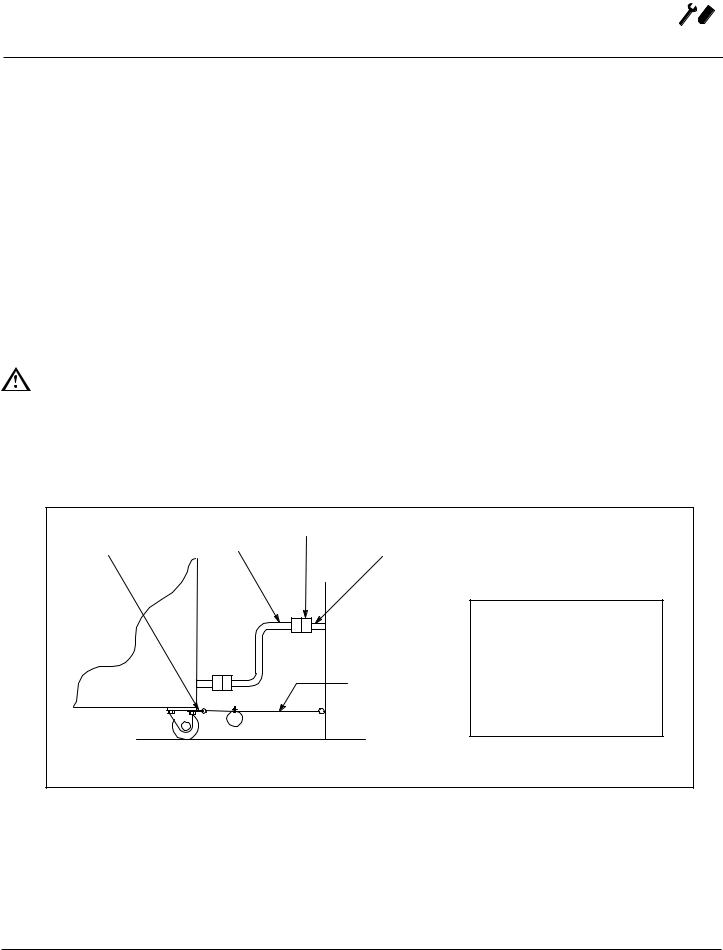
If the appliance is mounted on casters, a commercial flexible connector with a minimum of 3/4” (1.9 cm) inside diameter must be used along with a quick connect device.
A restraint must be used to limit the movement of the appliance so that no strain is placed upon the flexible connector. The restraint should be fastened to the base frame of the oven as close to the flexible connector as possible.
It should be short enough to prevent any strain on the connector. With the restraint fully stretched the connector should be easy to install and quick connect.
The restraint (ie: heavy gauge cable) should be attached without damaging the building. DO NOT use the gas piping or electrical conduit for the attachment of the permanent end of the restraint! Use anchor bolts in concrete or cement block. On wooden walls, drive hi test wood lag screws into the studs of the wall.
WARNING!!
If the restraint is disconnected for any reason it must be reconnected when the appliance is returned to its original position.
Gas Hose Restraint
U.S. and Canadian installations
The connector must comply with the Standard for Connectors for Movable Gas Appliances, ANSI Z21.69 or Connectors For Moveable Gas Appliances CAN/CGA-
6.16 and a quick disconnect device that complies with the
Standard for Quick-Disconnect Devices for Use With Gas Fuel, ANSI Z21.41 or Quick Disconnect For Use With Gas
Fuel CAN 1-6.9. Adequate means must be provided to limit the movement of the appliance without depending on the connection and the quick disconnect device or its associated piping.
A drip leg must be used at each appliance. Refer to NFPA54/ANSI Z223.1 - Latest Edition (National Fuel Gas Code) for proper drip leg installation.
General export installations
Installation must conform with Local and National installation standards. Local installation codes and/or requirements may vary. If you have any questions regarding the proper installation and/or operation of your appliance, please contact your local distributor. If you do not have a local distributor, please call Blodgett Combi at 0011-802- 658-6600.
Attachment Plate |
|
Quick Connect |
Gas Hose |
|
|
(secure with leg mount bolt) |
Gas Supply Line |
|
|
|
Restraint |
Installation of Gas Hose and Restraint
(Single Section Shown)
IMPORTANT: Cable restraint should be fastened as close as possible
to the flexible connector and short enough to prevent any strain on the flexible connector.
At maximum stretch of shortened restraint, the flexible connector should be easy to install and quick to connect.
Figure 8
13
 Loading...