


635549-00,FS2NC 7/13/05 10:10 AM Page 1 |
Brad Nailer / Stapler |
INSTRUCTION MANUAL |
Catalog Number
FS2NC
Catalog Number FSBN125 Shown
BEFORE RETURNING THIS PRODUCT FOR ANY REASON PLEASE CALL
1-800-544-6986
IF YOU SHOULD EXPERIENCE APROBLEM
WITH YOUR BLACK & DECKER PRODUCT,
CALL 1-800-544-6986
INMOSTCASES,ABLACK&DECKERREPRESENTATIVECANRESOLVEYOURPROBLEMOVER THEPHONE.IFYOUHAVEASUGGESTIONORCOMMENT,GIVEUSACALL.YOURFEEDBACKIS VITALTO BLACK&DECKER.
SAVE THIS MANUAL FOR FUTURE REFERENCE.
VEA EL ESPAÑOL EN LA CONTRAPORTADA.
INSTRUCTIVO DE OPERACIÓN, CENTROS DE SERVICIO
Y PÓLIZA DE GARANTÍA. ADVERTENCIA: LÉASE ESTE
INSTRUCTIVO ANTES DE USAR EL PRODUCTO.

635549-00,FS2NC 7/13/05 10:10 AM Page 2
SAFETY GUIDELINES / DEFINITIONS
 WARNING: Read and understand all instructions. Failure to follow all instructions listed below, may result in electric shock, fire and/or serious personal injury. The symbols below are used to help you recognize this information.
indicates an imminently hazardous situation which, if not avoided, will result in death or serious injury.


 indicates a potentially hazardous situation which, if not avoided, could result in death or serious injury.
indicates a potentially hazardous situation which, if not avoided, may result in minor or moderate injury.
used without the safety alert symbol indicates potentially hazardous situation which, if not avoided, may result in property damage.
SAVE THESE INSTRUCTIONS
 Read and understand all warnings and operating instructions before using any tool or equipment. When using tools or equipment, basic safety precautions should always be followed to reduce the risk of personal injury. Improper operation, maintenance or modification of tools or equipment could result in serious injury and property damage. There are certain applications for which tools and equipment are designed. Black & Decker strongly recommends that this product NOT be modified and/or used for any application other than for which it was designed.
GENERAL SAFETY RULES
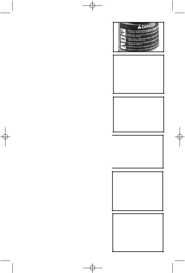
•Read and understand tool labels and manual.
Failure to follow warnings could result in DEATH or
SERIOUS INJURY. (Fig. 1)
•Operator and others in work area MUST wear safety glasses with side shields. These safety glasses must conform to ANSI Z87.1 requirements (approved glasses have “Z87” printed or stamped on them). (Fig. 2)
•Keep fingers AWAY from trigger when not driving fasteners to avoid accidental firing.
Never carry tool with finger on trigger. In "contact actuation mode", tool will fire a fastener if tool is bumped.
•Choice of triggering method is important.
Check manual for triggering options. See “Using the Tool“ section of this manual.
Fig. 1
Fig. 2
2
635549-00,FS2NC 7/13/05 10:10 AM Page 3
•Never point tool at yourself or others in work area. Serious injury or death may occur if the tool is activated. (Fig. 3)
•Never use oxygen or other bottled gasses.
Explosion will occur. Never use combustible gases or any other reactive gas as a power source for this tool: explosion and serious personal injury will result. (Fig. 4)
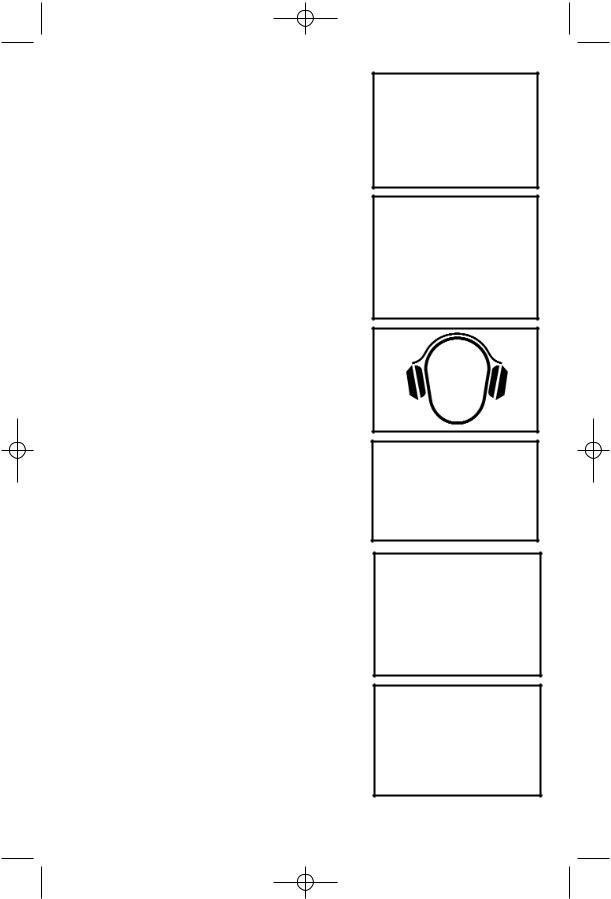
•Wear ear protection to safe-guard against possible hearing loss. Ear protection equipment must conform to ANSI S3.19 requirements. (Fig. 5)
•Use clean, dry, regulated, compressed air at 70 to 120 PSI, (4.8 to 8.3 BAR). (Fig. 6)
•Do not connect tool to pressure which potentially exceeds 200 PSI (13.7 BAR).
•All air line components (hoses, connectors, filters, regulators, etc.) must be rated for a maximum working pressure of at least 150 PSI (10.3 BAR) or 150% of the maximum system pressure, which ever is greater.
•Connect tool to air supply hose with a coupling that automatically removes all pressure from the tool when the coupling is disconnected. (Fig. 7).
•Disconnect tool from air supply hose before doing tool maintenance, clearing a jammed fastener, leaving work area, moving tool to another location, or handing the tool to another person. (Fig. 7)
•Never use a tool that is leaking air, has missing or damaged parts, or requires repair. Make sure all screws and caps are securely tightened.
(Fig. 8).
•Never use tool if safety, trigger or springs are inoperable, missing or damaged. Do not alter or remove safety, trigger, or springs. Make daily inspections for free movement of trigger and safety mechanism. (Fig. 8)
Fig. 3
Fig. 4
Fig. 5
Fig. 6
Fig. 7
Fig. 8
3
635549-00,FS2NC 7/13/05 10:10 AM Page 4
• Do not use tool without safety warning label. If |
|
|
Fig. 9 |
||
label is missing, damaged or unreadable, contact |
||
|
||
|
||
1-800-544-6986 for a replacement. (Fig. 9) |
|
•Only use parts, fasteners and accessories approved by Black and Decker.
•Connect tool to air supply before loading fasteners, to prevent a fastener from being fired during connection. The tool driving mechanism may cycle when tool is connected to the air supply. (Fig. 10)
•Always assume the tool contains fasteners. No
horseplay. Respect the tool as a working |
Fig. 11 |
implement. (Fig. 11) |
|
• Operator and bystanders should wear hard hats |
Fig. 12 |
to safeguard against possible injuries. (Fig. 12) |
|
|
|
•Do not load fasteners with trigger or safety depressed, to prevent unintentional firing of a fastener. (Fig. 13)
•Remove finger from trigger when not driving fasteners. Never carry tool with finger on trigger. In “Contact Actuation Mode” tool will fire a fastener if safety is bumped while trigger is depressed.
(Fig. 14)
Fig. 10
Fig. 13
Fig. 14
4
635549-00,FS2NC 7/13/05 10:10 AM Page 5
•Do not overreach. Keep proper footing and balance at all times when using or handling the tool.
•Fire fasteners into work surface only: never into materials too hard to penetrate. (Fig. 15)
•Grip tool firmly to maintain control while allowing tool to recoil away from work surface as fastener is driven. In “Contact Actuation Mode” if safety element is allowed to re-contact work surface before trigger is released an unwanted fastener will be fired.
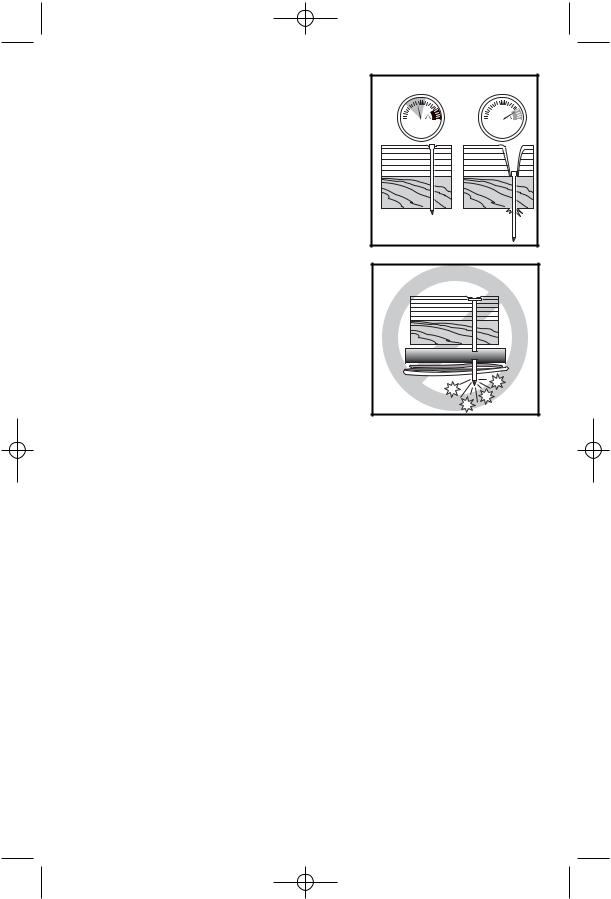
•Do not drive fasteners on top of other fasteners, or with the tool at too steep an angle: the fasteners can ricochet causing personal injury. (Fig. 15)
•Do not drive fasteners close to the edge of the workpiece. The workpiece is likely to split allowing the fastener to fly free or ricochet causing personal injury. (Fig. 16)
•FOR TOOLS USED IN CONTACT ACTUATION MODE, Do not use on scaffoldings or ladders or for tasks in which changing location involves the use of scaffoldings, stairs, ladders, and the like. Do not use for specific tasks such as closing boxes or crates or fitting transportation safety systems on vehicles and wagons. (Fig. 17)
•Keep bystanders, children, and visitors away while operating a power tool. Distractions can cause you to lose control.
•Make sure hose is free of obstructions or snags. Entangled or snarled hoses can cause loss of balance or footing.
•Always keep fingers clear of fastener track of magazine to prevent injury from inadvertent release of the pusher. (Fig. 18)
•Refer to the Maintenance section for detailed information on the proper maintenance of the tool.
•Always operate the tool in a clean, lighted area. Be sure the work surface is clear of any debris and be careful not to lose footing when working in elevated environments such as rooftops.
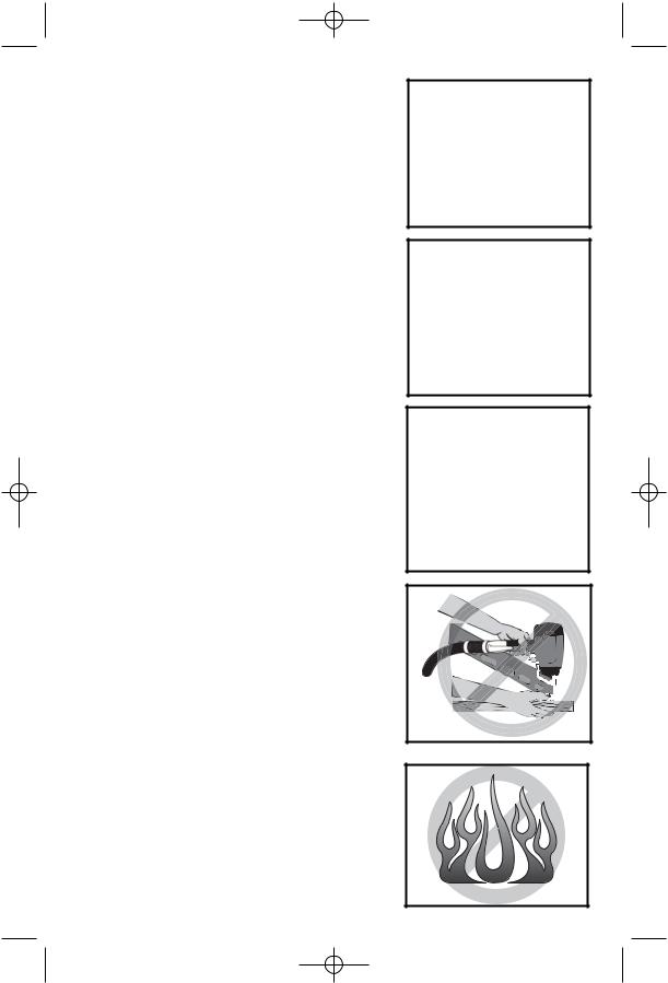
•Do not use tool in the presence of flammable dust, gases or fumes. The tool may produce a spark that could ignite gases causing a fire.
Driving a fastener into another fastener may also cause a spark. (Fig. 19)
Fig. 15
Fig. 16
Fig. 17
Fig. 18
Fig. 19
5
635549-00,FS2NC 7/13/05 10:10 AM Page 6
•Be aware of material thickness when using the fastener. A protruding fastener may cause injury.
•Be aware that when the tool is being utilized at pressures on the high end of its operating range, fasteners can be driven completely through thin or very soft work material. Make sure the pressure in the compressor is set so that fasteners are set into the material and not pushed completely through. (Fig. 20)
•Do not drive fasteners blindly into walls, floors or other work areas. Fasteners driven into live electrical wires, plumbing, or other types of obstructions can result in injury. (Fig. 21)
•Stay alert, watch what you are doing and use common sense when operating a power tool. Do not use tool while tired or under the influence of drugs, alcohol, or medication. A moment of inattention while operating power tools may result in serious personal injury.
 WARNING: Use of this product will expose you to chemicals known to the State of California to cause cancer, birth defects and other reproductive harm. Avoid inhaling vapors and dust, and wash hands after using.
Fig. 20 |
Fig. 21
6
635549-00,FS2NC 7/13/05 10:10 AM Page 7
FUNCTIONAL DESCRIPTION
The FSBN125 Nailer is designed to install 18 ga. brad nails of various lengths from 3/8" to 11/4" long. Brad nails are loaded into the magazine from the side.
The FSNS100 Stapler is designed to install 18 ga. narrow crown staples of various lengths from 3/8" to 1" long. Narrow crown staples are loaded into the magazine from the top.
POWER SOURCE
This tool is designed to operate on clean, dry, compressed air at regulated pressures between 70 and 120 PSI (Pounds per Square Inch)(4.8 to 8.3 BAR). The preferred system would include a filter, a pressure regulator, and an automatic oiler located as close to the tool as possible, within 15 ft/4.6 m is ideal.
All compressed air contains moisture and other contaminates that are detrimental to internal components of the tool. An air line filter will remove most of these contaminates and significantly prolong the life of the tool. If an in-line oiler is not available: place five or six drops of air tool oil into the tool’s air inlet on a daily basis.
The tool is equipped with a 1/4" male “quick connector”. The tool must always be connected to the air supply with a coupling such that all pressure is removed from the tool when the coupling is disconnected.
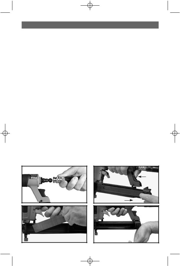
PREPARING THE TOOL
 Keep tool pointed in a safe direction when loading nails.
  Never load fasteners with the contact trip or trigger activated.
1.After reading and understanding this entire manual, connect tool to air supply. (Fig. 22)
2.Depress latch and slide magazine cover open. (Fig. 23)
3.Insert a strip of approved fasteners. (Fig. 24) Orient fasteners with points down in the magazine. NOTE: Brad nails are side loaded and staples are top loaded.
4.Push magazine cover closed. (Fig. 25)
5.Observe the low fastener indicator (A) Fig. 26 and reload as needed.
6.Adjust directional exhaust deflector (A) Fig. 27, so that the exhaust air or debris will be directed away from the operator. Grasp the deflector and rotate it to the desired position for the current application.
Fig. 22
Fig. 23
Fig. 24 |
Fig. 25 |
7

635549-00,FS2NC 7/13/05 10:10 AM Page 8
A |
Fig. 27 |
|
AFig. 26
OPERATING INSTRUCTIONS
USING THE TOOL
Complete all steps of PREPARING THE TOOL before using the tool.
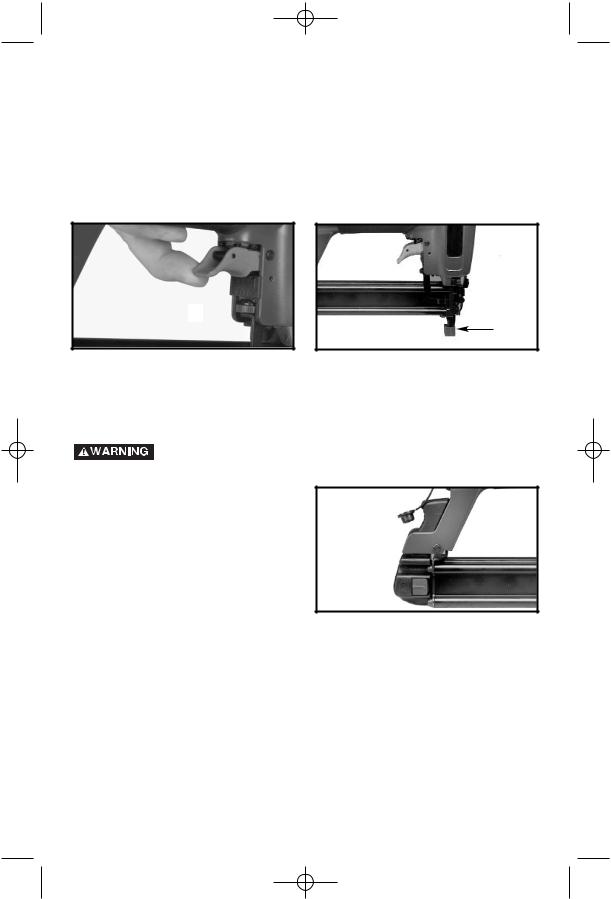
This tool is shipped from the factory with a “single sequential actuation” trigger. To fire, grip the tool firmly to maintain control, position nose of tool onto work surface, push the tool firmly against work surface to depress safety (S) Fig. 28, and squeeze trigger to fire a fastener. Allow tool to recoil away from work surface as fastener is driven. This “single sequential actuation” method provides the most accurate fastener placement.
 S
S
Fig. 28
 Disconnect tool from air supply before performing maintenance, clearing a jammed fastener, leaving work area, moving tool to another location, or handing the tool to another person.
Clean and inspect tool daily. Carefully check for proper operation of trigger and safety mechanism. Do Not use the tool unless both the trigger and the safety mechanism are functional, or if the tool is leaking air or needs any other repair.
8
635549-00,FS2NC 7/13/05 10:10 AM Page 9
The depth to which a fastener is driven is controlled by the depth adjustment knob (A) Fig. 29. The depth of drive is factory adjusted to a nominal setting. Test fire a fastener and check depth. If a change is desired, rotate the adjustment knob (A) Fig. 29. The adjustment knob has detents every 1/4 turn. Rotate the knob (A) Fig. 29 clockwise to increase the depth of drive, rotate the knob counterclockwise to decrease the depth of drive. Test fire another fastener and check depth. Repeat as necessary to achieve desired results. The amount of air pressure required will vary depending on the size of the fastener and the material being fastened. Experiment with the air pressure setting to determine the lowest setting that will consistently perform the job at hand. Air pressure in excess of that required can cause premature wear and/or damage to the tool.
Fig. 30
A
Fig. 29 |
A |
RUBBER NOSE CUSHION
A rubber nose cushion (A) Fig. 30 is provided to reduce marring of the work surface. The rubber cushion can be removed, and stored inside the magazine (B) Fig. 31 when it is not required.
Disconnect tool from air supply before removing or reinstalling rubber
cushion.
Fig. 31
B
CLEARING A JAMMED FASTENER
 Disconnect tool from air supply.
1.Open magazine and remove remaining fasteners. (Fig. 32 and Fig. 33)
 Remove fasteners from tool before opening the fastener guide plate. Fasteners are under pressure and may shoot out of magazine which could cause injury.
2.Open the quick release latch and the fastener guide plate. (Fig. 34)
3.Remove the jammed fastener. (Fig. 35)
4.Close the fastener guide plate, and the quick release latch.
9

635549-00,FS2NC 7/13/05 10:10 AM Page 10
Fig. 32
Fig. 34
Fig. 33
Fig. 35
MAINTENANCE
CLEAN AND INSPECT DAILY
 Disconnect tool from air supply before cleaning and inspection. Correct all problems before placing the tool back in use.
Wipe tool clean and inspect for wear or damage. Use non-flammable cleaning solutions to wipe exterior of tool only if necessary. DO NOT SOAK tool with cleaning solutions. Such solutions can damage internal parts.
Inspect trigger and safety mechanism to assure system is complete and functional: no loose or missing parts, no binding or sticking parts.
Keep all screws tight. Loose screws can cause personal injury or damage tool.
If tool is used without an in-line oiler: place five or six drops of air tool oil into the tool’s air inlet on a daily basis.
IMPORTANT: To assure product SAFETY and RELIABILITY, repairs, maintenance and adjustment (other than those listed in this manual) should be performed by authorized service centers or other qualified service organizations, always using identical replacement parts.
10
635549-00,FS2NC 7/13/05 10:10 AM Page 11
TROUBLESHOOTING
 Disconnect tool from air supply before performing any Service
Procedure.
SYMPTOM |
PROBLEMS |
SOLUTIONS |
1.Air leak near top of tool or in trigger area.
Loose screws. |
Tighten screws. |
Worn or damaged |
B&D service for overhaul. |
o-rings or seals. |
|
2.Tool does nothing or operates sluggishly.
Inadequate air supply. |
Verify adequate air supply. |
Inadequate lubrication. |
Put 5 or 6 drops of oil into air inlet. |
Worn or damaged |
B&D service for overhaul. |
o-rings or seals. |
|
3.Air leak near bottom of tool.
Loose screws. |
Tighten screws. |
Worn or damaged |
B&D service for overhaul. |
o-rings or bumper. |
|
4. |
Tool jams frequently. Incorrect fasteners. |
Verify approved fasteners of |
|
|
correct size. |
|
Damaged fasteners. |
Replace w/undamaged fasteners. |
|
Magazine or nose |
Tighten screws. |
|
screws loose. |
|
|
Magazine is dirty. |
Clean magazine. |
|
Driver is worn or damaged. B&D service for driver maintenance. |
|
|
|
|
5. |
Other. |
Contact a Black & Decker |
|
|
Service Facility. |
ACCESSORIES
Recommended accessories for use with your tool are available from your local retailer.
 The use of any accessory not recommended for use with this tool could be hazardous.
SERVICE INFORMATION
Black & Decker offers a full network of company-owned and authorized service locations throughout North America. All Black & Decker Service Centers are staffed with trained personnel to provide customers with efficient and reliable power tool service.
Whether you need technical advice, repair, or genuine factory replacement parts, contact the Black & Decker location nearest you.
To find your local service location, refer to the yellow page directory under “Tools— Electric” or call: 1-800-544-6986.
FULL TWO-YEAR HOME USE WARRANTY
Black & Decker (U.S.) Inc. warrants this product for two years against any defects in material or workmanship. The defective product will be replaced or repaired at no charge in either of two ways.
The first, which will result in exchanges only, is to return the product to the retailer from whom it was purchased (provided that the store is a participating retailer). Returns should be made within the time period of the retailer’s policy for exchanges (usually 30 to 90 days after the sale). Proof of purchase may be required. Please check with the retailer for their specific return policy regarding returns that are beyond the time set for exchanges.
The second option is to take or send the product (prepaid) to a Black & Decker owned or authorized Service Center for repair or replacement at our option. Proof of purchase
11
 Loading...