


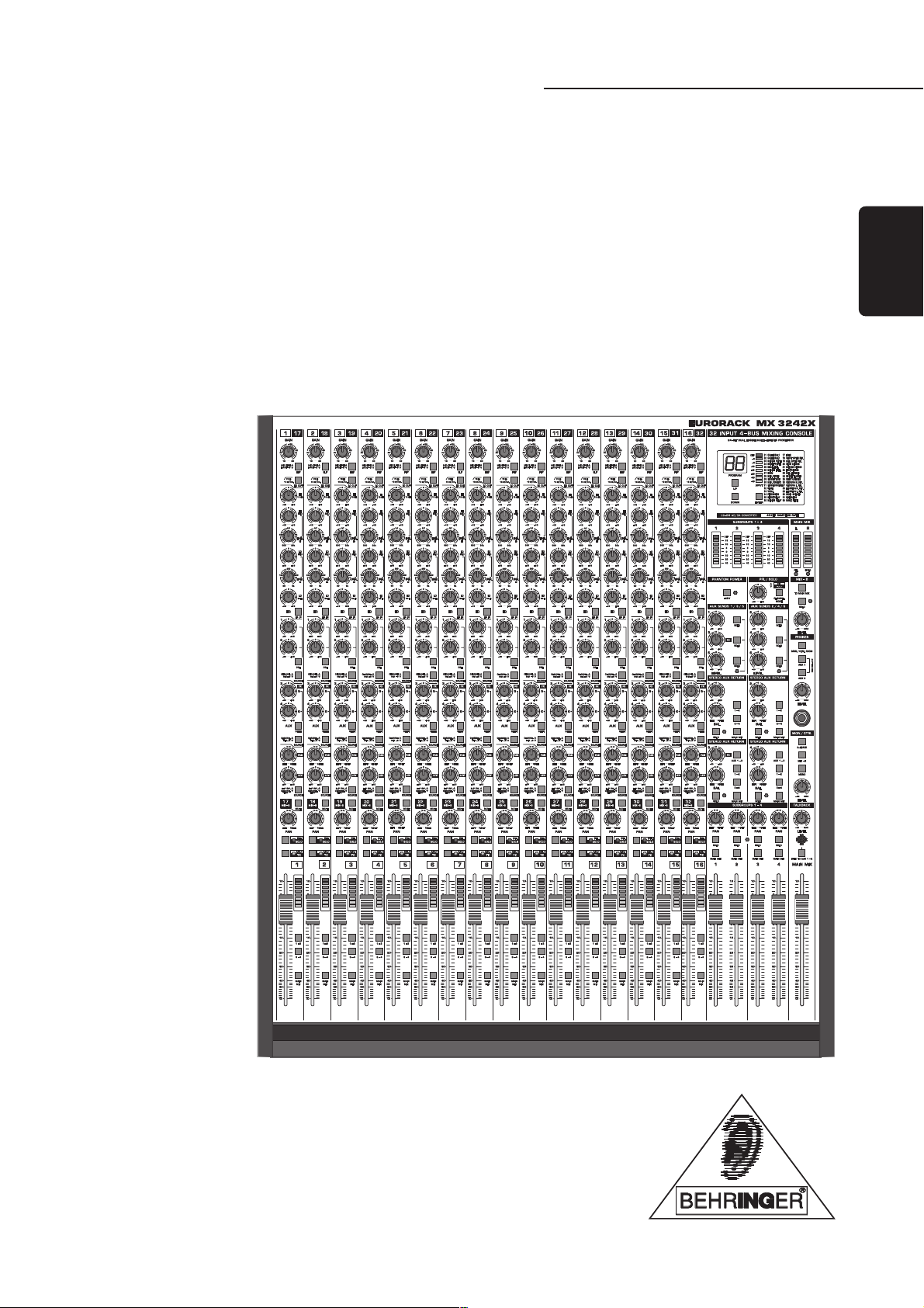
EURORACK MX3242X
Users Manual
EURORACK
®
MX3242X
Version 1.2 May 2001
www.behringer.com
ENGLISH
2
EURORACK MX3242X
This symbol, wherever it appears, alerts
you to important operating and mainte-
nance instructions in the accompanying
literature. Read the manual.
SAFETY INSTRUCTIONS
CAUTION: To reduce the risk of electric shock, do not remove
the cover (or back). No user serviceable parts inside;
refer servicing to qualified personnel.
WARNING: To reduce the risk of fire or electric shock, do not
expose this appliance to rain or moisture.
DETAILED SAFETY INSTRUCTIONS:
All the safety and operation instructions should be read before the appliance is operated.
Retain Instructions:
The safety and operating instructions should be retained for future reference.
Heed Warnings:
All warnings on the appliance and in the operating instructions should be adhered to.
Follow instructions:
All operation and user instructions should be followed.
Water and Moisture:
The appliance should not be used near water (e.g. near a bathtub, washbowl, kitchen sink, laundry tub, in a wet
basement, or near a swimming pool etc.).
Ventilation:
The appliance should be situated so that its location or position does not interfere with its proper ventilation.
For example, the appliance should not be situated on a bed, sofa, rug, or similar surface that may block the
ventilation openings, or placed in a built-in installation, such as a bookcase or cabinet that may impede the
flow of air through the ventilation openings.
Heat:
The appliance should be situated away from heat sources such as radiators, heat registers, stoves, or other
appliances (including amplifiers) that produce heat.
Power Source:
The appliance should be connected to a power supply only of the type described in the operating instructions
or as marked on the appliance.
Grounding or Polarization:
Precautions should be taken so that the grounding or polarization means of an appliance is not defeated.
Power-Cord Protection:
Power supply cords should be routed so that they are not likely to be walked on or pinched by items placed
upon or against them, paying particular attention to cords and plugs, convenience receptacles and the point
where they exit from the appliance.
Cleaning:
The appliance should be cleaned only as recommended by the manufacturer.
Non-use Periods:
The power cord of the appliance should be unplugged from the outlet when left unused for a long period of time.
Debris and Liquid Entry:
Care should be taken that debris and/or liquids do not enter the enclosure through openings.
Damage Requiring Service:
The appliance should be serviced by qualified service personnel when:
- The power supply cord or the plug has been damaged; or
- Debris or liquid has entered the appliance; or
- The appliance has been exposed to rain; or
- The appliance does not appear to operate normally or exhibits a marked change in performance; or
- The appliance has been dropped, or the enclosure damaged.
Servicing:
The user should not attempt to service the appliance beyond that which is described in the operating instruc-
tions. All other servicing should be referred to qualified service personnel.
This symbol, wherever it appears,
alerts you to the presence of
uninsulated dangerous voltage inside
the enclosurevoltage that may be
sufficient to constitute a risk of shock.

3
EURORACK MX3242X
FOREWORD
Dear Customer,
Welcome to the team of EURORACK users and thank you very much for expressing your confidence in
BEHRINGER products by purchasing this unit.
It is one of my most pleasant tasks to write this letter to you, because it is the culmination of many months of
hard work delivered by our engineering team to reach a very ambitious goal: To produce a compact mixer,
which fully satisfies your and our expectations and delivers a superior sound quality, easy operation and
technical specifications. In addition to that the mixer is affordable for almost every musician. The task to
design the EURORACK certainly meant a great deal of responsibility, which we assumed by focosing on you,
the discerning user and musician. It also meant a lot of work and night shifts to accomplish this goal. But it
was fun, too. Developing a product usually brings a lot of people together, and what a great feeling it is when
everybody who participated in such a project can be proud of what weve achieved.
It is our philosophy to share our joy with you, because you are the most important member of the BEHRINGER
family. With your highly competent suggestions for new products youve greatly contributed to shaping our
company and making it successful. In return, we guarantee you uncompromising quality (manufactured
under ISO9000 certified management system) as well as excellent technical and audio properties at an
extremely favorable price. All of this will enable you to fully unfold your creativity without being hampered by
budget constraints.
We are often asked how we can make it to produce such high-grade devices at such unbelievably low prices.
The answer is quite simple: its you, our customers! Many satisfied customers means large sales volumes
enabling us to get better conditions of purchase for components, etc. Isnt it only fair to pass this benefit back
to you? Because we know that your success is our success, too!
I would like to thank all people whose help on Project EURORACK MX3242X has made it all possible.
Everybody has made very personal contributions, starting from the designers of the unit via the many staff
members in my company to you, the user of BEHRINGER products.
My friends, its been worth the trouble!
Thank you very much,
Uli Behringer

4
EURORACK MX3242X
MX3242X
EURORACK
®
Ultra-low noise 16/32-channel 4-bus inline mixing console with integrated VIRTUALIZER multi-effects processor.
s 16 microphone input channels with gold-plated XLRs, TRS jacks, inserts and direct outputs
s Ultra-low noise discrete mic preamps with +48 V phantom power and switchable low cut filter
s 16 Line input channels with balanced TRS jack connectors
s 4 subgroups with independent pan control, solo and main mix switches and inserts
s 4 stereo aux returns with separate level and pan controls, solo and routing switches
s 2 pre / post and 4 post fader aux sends for a maximum effects and monitoring flexibility
s 6 master aux sends with gain control and solo switches
s 24-bit stereo multi-effects processor with ultra-high resolution 46 kHz, 20-bit AD/DA converters
s 32 original VIRTUALIZER presets including 16 different reverbs, delays, chorus, flanger, pitch shifter, speaker
simulation and various combinations
s Extremely high headroom offering a huge dynamic range
s Balanced inputs and main outputs for highest signal integrity
s Ultra-musical and original EURODESK 4-band EQ with two sweepable mids and I/O switch on all
channels
s LED controlled mute, solo-in-place / pre-fader-listen function on all channels
s Mix-B section with separate level and pan controls, mute and source switches
s Separate main mix, control room and headphone outputs
s Extremely versatile headphone and talkback section
s Highly accurate 8-segment bargraph meters on all channels, subgroups and main mix
s Ultra-high quality 100 mm faders for all channels, subgroups and main mix
s 19 inch rack mounting kit included
s Professional 19 inch external power supply ensures superior transient response
s State-of-the-art 4580 ICs and high quality components ensure crystal-clear audio performance
s Extremely rugged construction ensures long life even under the most demanding conditions
s Manufactured under ISO9000 certified management system

5
EURORACK MX3242X
TABLE OF CONTENTS
1. INTRODUCTION..................................................................................................................... 7
1.1 Concept .......................................................................................................................................... 7
1.1.1 Architecture .......................................................................................................................... 7
1.2 Before you start .............................................................................................................................. 8
1.2.1 Level meters ......................................................................................................................... 8
1.2.2 Power Supply Unit (PSU) ...................................................................................................... 9
1.2.3 Warranty ............................................................................................................................... 9
1.2.4 Shipping ............................................................................................................................... 9
1.2.5 Mounting the MX3242X in a rack ......................................................................................... 10
2. OPERATION .......................................................................................................................... 10
2.1 Main input channel ........................................................................................................................ 10
2.1.1 Input level setting ................................................................................................................. 11
2.1.2 Equalizer ............................................................................................................................ 12
2.1.3 Aux Send buses ................................................................................................................. 12
2.1.4 Routing, fading and muting .................................................................................................. 13
2.1.5 FLIP switch ......................................................................................................................... 14
2.2 Mix-B input channel ...................................................................................................................... 14
2.2.1 Input level setting ................................................................................................................ 14
2.2.2 Aux Send buses ................................................................................................................. 14
2.2.3 Routing ............................................................................................................................... 15
2.3 Insert points and direct outputs ..................................................................................................... 15
2.3.1 Main input channels ............................................................................................................ 16
2.3.2 Subgroups .......................................................................................................................... 16
2.3.3 Main mix ............................................................................................................................. 16
2.3.4 Direct output on each Main input channel ........................................................................... 16
2.4 Main section ................................................................................................................................. 17
2.4.1 Aux Send buses ................................................................................................................. 17
2.4.2 Aux Returns additional stereo line inputs ......................................................................... 17
2.4.3 Level meters ....................................................................................................................... 18
2.4.4 CHANNEL MODE and SOLO MASTER LEVEL controls ..................................................... 18
2.4.5 Mix-B .................................................................................................................................. 18
2.4.6 Monitor section ................................................................................................................... 19
2.4.7 Headphones section ........................................................................................................... 19
2.4.8 Subgroups and Main Mix fader ............................................................................................ 20
2.4.9 Digital Effects Processor ..................................................................................................... 20
2.4.10 Talkback facility: communicating with performers in the studio............................................ 22
3. PRACTISE ............................................................................................................................. 23
3.1 Selecting inputs ............................................................................................................................ 23
3.2 Initializing channels for gain setting ............................................................................................... 23
3.3 Auditioning a signal and setting up a channel................................................................................23
3.4 Desk normalization ....................................................................................................................... 23
3.5 Multi-track initialization ................................................................................................................. 23
3.6 Recording levels ............................................................................................................................ 23
3.7 Track sheet ................................................................................................................................... 24

6
EURORACK MX3242X
4. APPLICATIONS ..................................................................................................................... 24
4.1 Recording situation ....................................................................................................................... 24
4.2 Live situation ................................................................................................................................. 25
4.3 Patchbay ...................................................................................................................................... 26
4.3.1 Patchbay configuration ........................................................................................................ 26
4.3.2 Parallel ............................................................................................................................... 26
4.3.3 Half-normalled ..................................................................................................................... 26
4.3.4 Normalled ........................................................................................................................... 27
4.3.5 Open ................................................................................................................................... 27
4.3.6 Patchbay organization ........................................................................................................ 27
4.3.7 Looming problems .............................................................................................................. 29
4.4 Expanding the MX3242X ............................................................................................................... 29
4.4.1 Expander Port ..................................................................................................................... 29
4.4.2 Modifications....................................................................................................................... 30
5. TECHNICAL BACKGROUND .............................................................................................. 33
5.1 Mixing ........................................................................................................................................... 33
5.1.1 Equalization ........................................................................................................................ 33
5.1.2 Gain optimization ................................................................................................................ 34
6. INSTALLATION .....................................................................................................................34
6.1 Rack mounting .............................................................................................................................. 34
6.2 Mains connection .......................................................................................................................... 35
6.3 Audio connections ........................................................................................................................ 35
7. APPENDIX ............................................................................................................................. 37
7.1 Specifications ................................................................................................................................ 37
7.2 Track sheet ................................................................................................................................... 38
8. WARRANTY ........................................................................................................................... 39

7
EURORACK MX3242X
1. INTRODUCTION
Congratulations! In purchasing the BEHRINGER EURORACK MX3242X you have acquired a mixing console
whose compact size belies its incredible versatility and superlative audio performance. Your EURORACK is
built to the same outstanding quality as our top-of-the-range console, the BEHRINGER EURODESK MX9000.
With its 19", 12 HU size it fits in a standard rack. When you mount the side panels, you can also use it as a
table-top model. The interface panel on the rear can be rotated easily and thus gives you convenient access
to all connectors, even when the MX3242X is installed in a rack.
With its complete range of sophisticated routing options, the EURORACK MX3242X is a perfect tool for both
live and studio applications. Various modifications enable you to customize the console to suit your specific
requirements. You can use the EURORACK as a recording or live console, as a live console with
simultaneous multi-track recording facilities, as a sub-mixer, surround mixer, etc.
Another outstanding feature of your MX3242X is its on-board digital 24-bit Effects Processor. We designed a
scaled-down version of our well-known VIRTUALIZER, which nevertheless has the same 20-bit AD/DA
converters, 24-bit DSP, 46 kHz sample rate and algorithms as our 19" unit. Which means, you can choose
from 32 presets with first-class Reverb, Delay and modulation effect algorithms.
Below in this handbook youll find some information on how to enhance the consoles functionality even further
by using the Expansion Port to feed additional line signals in your MX3242X. At the moment, we are planning
an expansion module that can be used both as a stand-alone rack mixer and as an expansion to your MX3242X
making it a future-oriented and upgradable mixing console that grows with your needs. First of all, however,
wed like to take you on a guided tour of all the sights of your BEHRINGER EURORACK MX3242X.
We recommend that you experiment with your EURORACK away from the pressure of a recording session or
live concert, in order to get a feel for it. After all, its a musical instrument. Learn to play it well.
Most specialist subjects are not really as difficult as they may seem at first provided you understand the
language used. The vocabulary of mixing is pretty straightforward: a slot in a recorder will always be
referred to as a track, while that in a mixer is a channel. We will try to be as unambiguous as possible with
terms, since much confusion can arise from sloppy definitions.
On a separate sheet you will find some drawings showing all control elements and a block diagram respec-
tively. All control elements will be numbered consistently throughout the manual, whether they be in the text or
on an illustration.
1.1 Concept
The EURORACK MX3242X is a cross between split and inline designs. The input channels are located in
the larger left-hand section of the console, while the outputs to a multi-track recorder can be found on the
right (Subgroups). In contrast to conventional split consoles, however, the Tape Returns coming from the
multi-track recorder (feeding the tape signal back to the mixer) are not located in the outputs section but are
integrated in the input channels (as it is typical of an inline console). Thus, the input channel functions can
also be used for the Tape Returns. And later, during the mixdown this design ensures a signal path that is as
short as possible.
The MX3242X is configured as a 32/16 in 4 in 2 console, i.e. you have 16 input channels, 4 Subgroups and
16 monitor inputs for the Tape Returns. You can use one Main Mix, 4 Subgroup and 16 channel faders, each
with a control range of 100 mm. Since the monitor channels (called Mix-B in the following) can be routed to
the Main Mix bus, you can use 32 channels during mixdown. With the 6 Aux Returns and 4 Subgroups (which
can be fed via their insert points using a special cable), you have a total of 42 channels available.
On the EURORACK MX3242X you can control 6 Aux buses with 4 rotary controls. Aux buses 1 and 2 are
used for monitor mixes, and the talkback facility ensures straightforward communication between engineer
and artist. For live applications you can use the Mix-B bus as an additional monitor bus, and the 4 mono post-
fader Aux buses to drive external effects devices.
The input/output section comprises Microphone inputs (with 48 V phantom power), Line inputs, multi-track
connectors, various insert points as well as connectors for a 2-Track master recorder (e.g. DAT) and a
monitor system (monitor speaker with power amp).
1. INTRODUCTION

8
EURORACK MX3242X
1.1.1 Architecture
Main input channels
Channels 1 through 16 are configured as mono channels with balanced Microphone and Line connectors. The
discrete vintage-type microphone preamps in high-current technology have the same excellent quality as the
amplifiers in our legendary BEHRINGER EURODESK MX9000. An overdimensioned external 19" power supply
unit eliminates hum interference and ensures perfect pulse response even with signal transients. The insert
jacks give the Main input channels a similar functionality as can be found in big mixing consoles.
Mix-B input channels
The MX3242X provides another 16 Line inputs whose operating level can be switched between +4 dBu and
-10 dBV, making these inputs ideally suited for use as multi-track Tape Returns or to connect MIDI and other
electronic devices.
Subgroups
The four Subgroups can be used to feed signals to a multi-track recorder. In live applications they also allow
for combining several instruments, control their volumes with just one fader and send the resulting sub-mix
signal to the Main Mix bus.
Channel outputs
The channel signal passes a high-grade logarithmic 100-mm fader, to be routed to the Subgroups and/or the
Main Mix bus.
Aux Sends
The MX3242X features 6 Aux Send buses (2 pre/post, 4 post-fader), which can receive their signals both
from the Main channel and from the Mix-B input. The third Aux Send is marked FX and is routed to the
consoles on-board multi-effects processor, but can also be used for external effects devices.
Stereo Aux Returns (additional stereo Line inputs)
The MX3242X is equipped with 4 stereo Aux Returns located above the Subgroups. The inputs can be used
as stereo effect return or additional Tape Return inputs. As an alternative, you can also connect MIDI
instruments. The third Aux Return carries the signal from the on-board effects processor, however, can also
be used as an additional Line input, so that the outputs of the on-board effects device are not routed to Aux
Return 3.
Main Mix output (master)
The MX3242X has an extremely high-grade logarithmic 100-mm stereo fader to control the level of the master
outputs.
24-bit digital Effects Processor
The on-board 24-bit digital Effects Processor features first-class algorithms, similar to those used in our
VIRTUALIZER, and offers all standard effect types such as Reverb, Chorus, Flanger, Delay, etc. With its
excellent audio quality it can be used both for mixdowns, live concerts and monitoring.
Other highlights of the MX3242X are: an adjustable headphones output (stereo headphones mix possible!), a
separate 2-Track in/output as well as the Expansion Port mentioned above. Insert points are available on the
Main channels, Subgroups and Main Mix bus. Additionally, each Main channel has a direct output which can
be modified. Thus, the MX3242X can handle up to 20 tracks in a multi-track environment by adding the Aux
Return inputs and routing them to the Subgroups. And all this in a compact enclosure of 19" and 12 HU. So,
there is no reason why you shouldnt use your EURORACK for mobile applications, too.
1.2 Before you start
1.2.1 Level meters
Fig. 1.1: Subgroup and Main Mix level meters
1. INTRODUCTION
9
EURORACK MX3242X
Each of the Main input channels, the Subgroups and the Main Mix bus are equipped with 8-segment, 3-color
LED level meters ( , and ), which help you set levels correctly and avoid distortion. When your
MX3242X is shipped from the factory, the level meters are configured post-fader, but can also be modified to
display pre-fader signals (cf. 4.4.2 Modifications).
The level meters should average around 0 dB during loud passages. If they read persistently higher, or are
peaking above +10 dB, you should move the faders down a bit. As a last resort you can also reduce the input
gain in the channels. Always work with the PFL function and make sure that the red CLIP LED in the level
meters wont light up.
+ When you activate the MUTE switch, the level meters in the main input channels offer you two
helpful functions: If a signal is present in the main input channel, the lowest green LED lights
up (signal present). If the gain setting is too high, the red CLIP LED on top of the channel level
meter lights up. So you are able to control the main input channels signal, even when the
MUTE switch is activated.
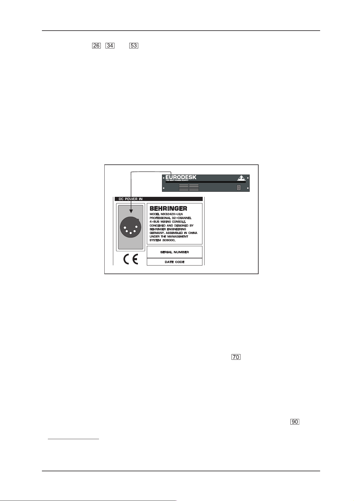
1.2.2 Power Supply Unit (PSU)
Fig. 1.2: Connecting the Power Supply
Any amplifier circuit is limited in its transient response by the available current. Every mixer has numerous
operational amplifiers (op-amps) inside to process line level signals. When being driven hard, many desks
begin to show signs of stress due to power supply limitations. Not so with the EURORACK: the sound will
always stay clean and transparent right up to the operating limits of the op-amps themselves, thanks to the
overdimensioned external 150-W PSU. Mounted in a 19" enclosure (2 ½ rack units), the EURORACKs PSU
is connected on the rear with a multi-pin connector. However, you should make sure that 3 HU are available to
ensure proper airflow around the heat sinks.
Please connect the Power Supply to the PSU connector (Power Supply Unit) on the rear of your EURORACK
MX3242X before you connect it to the mains.
+ Never connect the PSU to the EURORACK while the PSU is connected to the mains supply!
+ Only use the enclosed power cord to connect the PSU to the mains.
1.2.3 Warranty
Please ask your specialized retailer to fill in the warranty card, then send it back to us within 14 days after the
date of purchase. Otherwise you will lose your extended warranty rights. The serial number of your
MX3242X can be found on the rear of the console. Or use our onlineregistration option available on the Internet
at www.behringer.com.
1. INTRODUCTION
10
EURORACK MX3242X
1.2.4 Shipping
Your EURORACK MX3242X was carefully packed in the factory and the packaging was designed to protect the
unit from rough handling. Nevertheless, we recommend that you carefully examine the packaging and its
contents for any signs of physical damage, which may have occurred in transit.
+ If the unit is damaged, please do not return it to us, but notify your dealer and the shipping
company immediately. Otherwise claims for damage or replacement may not be granted.
1.2.5 Mounting the MX3242X in a rack
In the shipping carton youll find two 19" mounting angles which can be fixed to the side panels of the console.
Remove the side panels by loosening the screws (3 per side) that fix them to the console, lay the panels aside
and use the screws to fasten the mounting angles. Please note that each angle can be mounted on a specific
side only.
To be able to reach the rear connectors when the MX3242X is mounted in a rack, you should rotate the
interface panel by 90° (after loosening the screws holding it), and refix it. The following screws must be
removed:
1) 4 screws on the upper part of the interface panel.
2) Another 4 screws on the cover plate directly mounted to the interface panel at an angle of 90°.
3) 6 screws each on the left and right side panels.
Once the interface panel has been rotated, please check that all ribbon cables are seated and connected
properly. Then tighten all screws.
+ Ensure sufficient air space around the MX3242X. Never mount the unit in close proximity to a
power amp or similar device to avoid overheating.
+ Please note that both PSU and EURORACK will heat up during operation. This is completely
normal and does not indicate a malfunction.
2. OPERATION
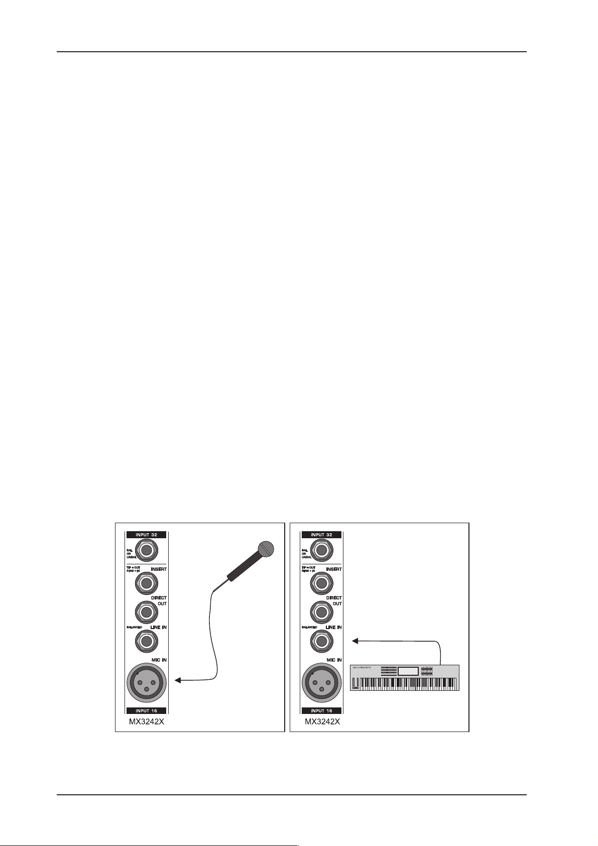
2.1 Main input channel
Fig. 2.1: Connecting a signal source to a Main input channel
1. INTRODUCTION
11
EURORACK MX3242X
Each mono channel features a balanced Line input on a ¼" jack and a balanced Microphone input on an
XLR connector .
Fig. 2.2: Phantom power switch
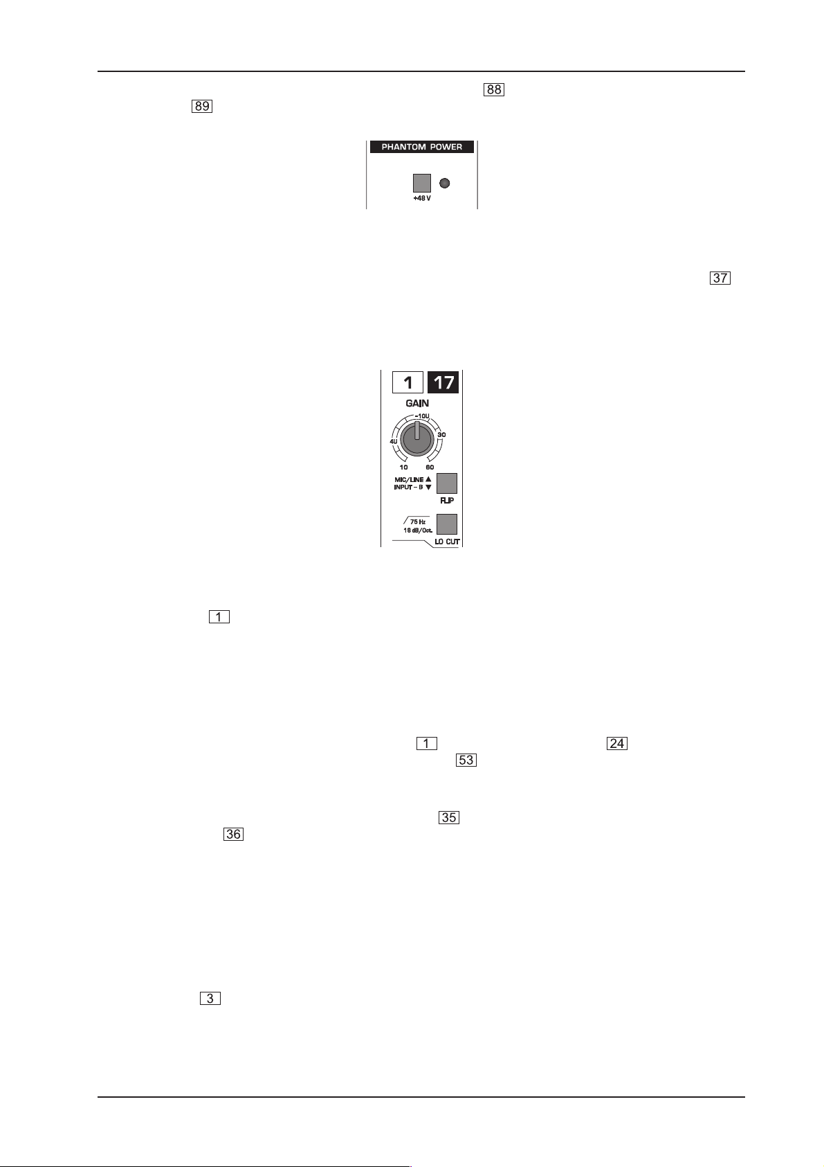
The +48 V phantom power required for condenser mics can be activated with the phantom power button in
the Main section. If activated, the LED next to the button lights up.
+ Mute the sound system before you turn on phantom power. Otherwise, power-up thumps could
be played back by the monitor speakers.
Fig. 2.3: Gain control and Lo Cut filter
The Gain control has a very wide range, obviating the need for Mic/Line switching. The levels most
commonly used are -10 dBV and +4 dBu, and are clearly labelled.
+ Please note that you can only use either of the Mic and Line inputs, but never both at the same
time!
2.1.1 Input level setting
Channel input level is determined by the Gain control . Use the PFL/SOLO button to bring the left and
right portions of the input signal onto the level meters in the Main section. This also sends the
SOLO/PFL-signal to the speakers.
For overall level setting you should use the mono PFL bus rather than the post-fader and post-channel-pan
SOLO bus. Make sure that the CHANNEL MODE button is not pressed. We recommend that you set the
level potentiometer for the PFL/SOLO function to 0 dB (12 oclock). In loud environments (e.g. live
application), you can of course raise the PFL/SOLO volume as required.
+ Please note that too high a monitoring level can lead to hearing damage.
Using the PFL/SOLO function does not affect the signal that is supplied by the recording outputs, and the
same applies to the Aux buses.
In addition to channel level metering in the Main section, each single channel has its own LED chain
indicating the level of the post-fader channel signal (see section 1.2.1). This option allows you to detect and
correct excessive or insufficient levels quickly, even without having to activate the PFL/SOLO function.
The Lo Cut filter with its high slope of 18 dB/Oct. (-3 dB at 75 Hz) eliminates unwanted subsonics.
2. OPERATION
12
EURORACK MX3242X
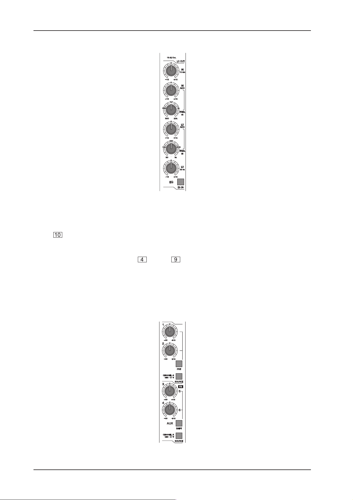
2.1.2 Equalizer
Fig. 2.4: Equalizer
In addition to the Lo Cut filter, all Main input channels come with a 4-band Equalizer with two tunable midrange
bands, each having up to 15 dB of cut and boost. In center detent position the EQ is off. With the EQ IN
button you can activate/bypass the Equalizer, so as to allow for easy comparisons of EQ-ed and
unprocessed signals. If you dont use the Equalizer, dont press the EQ IN button.
The HI and LO bands work with shelving-type filters raising or lowering all frequencies beyond the selected
value. The cutoff frequencies of the HI and LO bands are 12 kHz and 80 Hz respectively. In the
midrange band, the MX3242X provides two tunable peaking-type filters emphasizing the center frequency
with a filter quality of one octave. The HI MID band can be tuned from 300 Hz through 20 kHz, the LO MID
band from 50 Hz through 3 kHz. Use controls 6 and 8 to select the center frequencies of the two midrange
bands, and controls 5 and 7 to determine cut/boost.
2.1.3 Aux Send buses
Fig. 2.5: Aux Sends
2. OPERATION
 Loading...