


User Manual
Thank you
Thank you for choosing a BEHRINGER EUROPOWER amplifier. This piece of high-end gear was developed for professional use in live applications, and its many features make it a useful and dependable part of your sound system.
The EUROPOWER amps feature an input filter for each channel, enabling you to remove the low-frequency portion of the signal, if desired. Additionally, there is a limiter that protects your loudspeakers. Various operating modes, such as parallel or mono-bridged mode, open up various possibilities for effective
implementation with the rest of your audio equipment for almost any application.
This manual first describes the controls and connection points so that you fully understand the EUROPOWER amplifier and its functions. Then it delves into the various applications where the EUROPOWER amp can be used, and finishes with more details on installing and making the connections to the amplifier.
Have fun with your new amplifier.
This manual is available in English, German, French, Spanish, Italian, Russian, Polish, Dutch, Finnish, Swedish, Danish, Portugese, Greek, Japanese and Chinese. There may also be more current versions of this document. Download them by going to the appropriate product page at:
www.behringer.com
ENGLISH
EUROPOWER
EP2000/EP4000
Professional 2,000-Watt
and 4,000-Watt Stereo Power Amplifier with ATR (Accelerated Transient
Response) Technology
Table of Contents |
|
|
Thank you...................................................................... |
1 |
|
Important Safety Instruction...................................... |
2 |
|
1. Introduction............................................................. |
3 |
|
1.1 |
Before you get started.................................................................. |
3 |
2. Control elements..................................................... |
4 |
|
2.1 |
Front panel......................................................................................... |
4 |
2.2 |
Rear panel........................................................................................... |
4 |
2.3 |
Configuration switches (MODE SWITCHES)........................ |
5 |
3. Applications............................................................. |
6 |
|
3.1 |
Differences between 2-channel, parallel and |
|
mono-bridged operating modes ................................................... |
6 |
|
3.2 |
Bi-amping........................................................................................... |
9 |
4. Installation............................................................. |
10 |
|
4.1 |
Connections................................................................................... |
10 |
4.2 |
Audio connections...................................................................... |
11 |
5. Specifications......................................................... |
12 |
|
Legal Disclaimer......................................................... |
13 |
|
Warranty...................................................................... |
14 |
|
A50-A3830-08001

ENGLISH
2 |
EUROPOWER EP2000/EP4000 User Manual |
|
Important Safety Instruction
* Caution
This symbol, wherever it appears, alerts you to the presence of uninsulated dangerous voltage inside the enclosure - voltage that may be sufficient to constitute a risk of shock.
!!Caution
This symbol, wherever it appears, alerts you to important operating and maintenance instructions in the accompanying literature. Please read the manual.
!!Caution
◊To reduce the risk of electric shock, do not remove the top cover (or the rear section). No user serviceable parts inside.
Refer servicing to qualified personnel.
◊To reduce the risk of fire or electric shock, do not expose this appliance to rain and moisture. The apparatus shall not be exposed to dripping or splashing liquids and no objects filled with liquids, such as vases, shall be placed on the apparatus.
◊These service instructions are for use by qualified service personnel only. To reduce the risk of electric shock do not perform any servicing other than that contained in the operation instructions. Repairs have to be performed by qualified service personnel.
◊We would like to bring your attention to the fact that extremely loud sound levels may damage your hearing as well as your loudspeakers. Please lower both GAIN controls leftwards before powering up the unit. Be sure to keep the volume at an appropriate level.
◊Ventilation: The appliance should be situated so that its location or position does not interfere with its proper ven- tilation. For example, the appliance should not be situated on a bed, sofa rug, or similar surface that may block the ventilation openings: or placed in a built-in installation, such as a bookcase or cabinet that may impede the flow of air through the ventilation openings.
!!Caution
{1}. Read these instructions. {2}. Keep these instructions. {3}. Heed all warnings.
{4}. Follow all instructions.
{5}. Do not use this apparatus near water. {6}. Clean only with dry cloth.
{7}. Do not block any ventilation openings. Install in accordance with the manufacturer’s instructions.
{8}. Do not install near any heat sources such as radiators, heat registers, stoves, or other apparatus (including amplifiers) that produce heat.
{9}. Do not defeat the safety purpose of the polarized or grounding-type plug. A polarized plug has two blades with one wider than the other. A groundingtype plug has two blades and a third grounding prong.The wide blade or the third prong are provided for your safety. If the provided plug does not fit into your outlet, consult an electrician for replacement of the obsolete outlet.
[10].Protect the power cord from being walked on or pinched particularly at plugs, convenience receptacles, and the point where they exit from the apparatus.
[11].Only use attachments/accessories specified by the manufacturer
[12].Use only with the cart, stand, tripod, bracket, or table
specified by the manufacturer, or sold with the apparatus.When a cart is used, use caution when moving the cart/apparatus combination to avoid injury from tip-over.
[13].Unplug this apparatus during lightning storms or when unused for long periods of time.
[14].Refer all servicing to qualified service personnel. Servicing is required when the apparatus has been damaged in any way, such as power supply cord or plug is damaged, liquid has been spilled or objects have fallen into the apparatus, the apparatus has been exposed to rain or moisture, does not operate normally, or has been dropped.
[15].The apparatus shall be connected to a MAINS socket outlet with a protective earthing connection.
[16].Where the MAINS plug or an appliance coupler is used as the disconnect device, the disconnect device shall remain readily operable.

EUROPOWER EP2000/EP4000 User Manual
1. Introduction
Honestly, who really likes to read manuals? We know you want to get started right away, but please read this manual carefully and keep it for future reference. It is only after reading these instructions that you will fully understand and be able to use all the features your EUROPOWER amplifier has to offer.
1.1 Before you get started
1.1.1 Shipment
Your EUROPOWER was carefully packed at the factory, and the packaging is designed to protect the unit from rough handling. Nevertheless, we recommend that you carefully examine the packaging and its contents for any signs of physical damage, which may have occurred during transit.
◊If the unit is damaged, please do NOT return it to BEHRINGER, but notify your dealer and the shipping company immediately. Otherwise, claims for damage or replacement may not be granted.
1.1.2 Initial operation
Please make sure the unit is provided with sufficient ventilation, and never place your EUROPOWER amp on top of other heatemanating equipment or in the vicinity of a heater to avoid the risk of overheating.
The mains connection is made via the enclosed power cord and a standard IEC receptacle. It meets all international safety certification requirements.
◊Please make sure that all units have a proper ground connection. For your own safety, never remove or disable the ground conductor from the unit or the AC power cord.
◊The sound quality may diminish within the range of powerful broadcasting stations and high-frequency sources. Increase the distance between the transmitter and the device and use shielded cables for all connections.
3
1.1.3 Online registration
Please register your new BEHRINGER equipment right after your purchase by visiting http://www.behringer.com and read the terms and conditions of our warranty carefully.
Should your BEHRINGER product malfunction, it is our intention to have it repaired as quickly as possible. To arrange for warranty service, please contact the BEHRINGER retailer from whom the equipment was purchased. Should your BEHRINGER dealer not be located in your vicinity, you may directly contact one of our subsidiaries. Corresponding contact information is included in the original equipment packaging (Global Contact Information/European Contact Information). Should your country not be listed, please contact the distributor nearest you. A list of distributors can be found in the support area of our website (http://www.behringer.com). Registering your purchase and equipment with us helps us process your repair claims more quickly and efficiently.
Thank you for your cooperation!
ENGLISH

ENGLISH
4 |
EUROPOWER EP2000/EP4000 User Manual |
|
2. Control elements
2.1 Front panel
|
|
|
|
|
|
|
|
|
|
|
|
|
|
|
|
|
|
|
|
|
|
|
|
|
|
|
|
|
|
|
|
|
|
|
|
|
|
|
|
|
|
|
|
|
|
|
|
|
|
|
|
|
|
|
|
|
|
|
|
|
|
|
|
|
|
|
|
|
|
|
|
|
|
|
|
|
|
|
|
|
|
|
|
|
|
|
|
|
|
|
|
|
|
|
|
|
|
|
|
|
|
|
|
|
|
|
|
|
|
|
|
|
|
|
|
|
|
|
|
|
|
|
|
|
|
|
|
|
|
|
|
|
|
|
|
|
|
|
|
|
|
|
|
|
|
|
|
|
|
|
|
|
|
|
|
|
|
|
|
|
|
|
|
|
|
|
|
|
|
|
|
|
|
|
|
|
|
|
|
|
|
|
|
|
|
|
|
|
|
|
|
|
|
|
|
|
|
|
|
|
|
|
|
|
|
|
|
|
|
|
|
|
|
|
|
|
|
|
|
|
|
|
|
|
|
|
|
|
|
|
|
|
|
|
|
|
|
|
|
|
|
|
|
|
|
|
|
|
|
|
|
|
|
|
|
|
|
|
|
|
Fig. 2.1: Front panel control elements |
|
|
|
|
|
|
|
|
|
|
|
|
|
|
|
|
|
|||||||||||
Since control elements of both the EP2000 and the EP4000 are |
[3] The CLIP LED lights up when the signal is distorted. |
|||||||||||||||||||||||||||
identical, we have used the EP2000 as the model represented in |
Should distortion occur, reduce the input level, so that the |
|||||||||||||||||||||||||||
the illustrations to assure simplicity. |
CLIP LED stops lighting up. |
|||||||||||||||||||||||||||
[1] The main switch is used to power up the amp. |
[4] The SIGNAL LED lights up as long as a signal is present at |
|||||||||||||||||||||||||||
◊ Merely switching the unit off does not mean that it is fully |
the input. |
|||||||||||||||||||||||||||
disconnected from the mains. When not using the unit for |
[5] The Gain control (channels 1 and 2) is used for setting up |
|||||||||||||||||||||||||||
prolonged periods of time, please unplug the unit’s power |
the input gain. |
|||||||||||||||||||||||||||
cord from the power outlet. |
[6] The POWER LED lights up as soon as the unit is |
|||||||||||||||||||||||||||
[2] Ventilation openings are located at the front of the unit, so |
powered up. |
|||||||||||||||||||||||||||
that hot air is prevented from being trapped inside the unit, |
|
|
|
|
|
|
|
|
|
|
|
|
|
|
|
|
|
|||||||||||
thus causing faulty operation or even damage. |
|
|
|
|
|
|
|
|
|
|
|
|
|
|
|
|
|
|||||||||||
2.2 Rear panel
|
|
|
|
|
|
|
|
|
|
|
|
|
|
|
|
|
|
|
|
|
|
|
|
|
|
|
|
|
|
|
|
|
|
|
|
|
|
|
|
|
|
|
|
|
|
|
|
|
|
|
|
|
|
|
|
|
|
|
|
|
|
|
|
|
|
|
|
|
|
|
|
|
|
|
|
|
|
|
|
|
|
|
|
|
|
|
|
|
|
|
|
|
|
|
|
|
|
|
|
|
|
|
|
|
|
|
|
|
|
|
|
|
|
|
|
|
|
|
|
|
|
|
|
|
|
|
|
|
|
|
|
|
|
|
|
|
|
|
|
|
|
|
|
|
|
|
|
|
|
|
|
|
|
|
|
|
|
|
|
|
|
|
|
|
|
|
|
|
|
|
|
|
|
|
|
|
|
|
|
|
|
|
|
|
|
|
|
|
|
|
|
|
|
|
|
|
|
|
|
|
|
|
|
|
|
|
|
|
|
|
|
|
|
|
|
|
|
|
|
|
|
|
|
|
|
|
|
|
|
|
|
|
|
|
|
|
|
|
|
|
|
|
|
|
|
|
|
|
|
|
|
|
|
|
|
|
|
|
|
|
|
|
|
|
|
|
|
|
|
|
|
|
|
|
|
|
|
|
|
|
|
|
|
|
|
|
|
|
|
|
|
|
|
|
|
|
|
|
|
|
|
|
|
|
|
|
|
|
|
|
|
|
|
|
|
|
|
|
|
|
|
|
|
|
|
|
|
|
|
|
|
|
|
|
|
|
|
|
|
|
|
|
|
|
|
|
|
|
|
|
|
|
|
|
|
|
|
|
|
|
|
|
|
|
|
|
|
|
|
|
|
|
|
|
|
|
|
|
|
|
|
|
|
|
|
|
|
|
|
|
|
|
|
|
|
|
|
|
|
|
|
|
|
|
|
|
|
|
|
|
|
|
|
|
|
|
|
|
|
|
|
|
|
|
|
|
|
|
|
|
|
|
|
|
|
|
|
|
|
|
|
|
|
|
|
|
|
|
|
|
|
|
|
|
|
|
|
|
|
|
|
|
|
|
|
|
|
|
|
|
|
|
|
|
|
|
|
|
|
|
|
|
|
|
|
|
|
|
|
|
|
|
|
|
|
|
|
|
|
|
|
|
|
|
|
|
|
|
|
|
|
|
|
|
|
|
|
|
|
|
|
|
|
|
|
|
|
|
|
|
|
|
|
|
|
|
|
|
|
|
|
|
|
|
|
|
|
|
|
|
|
|
|
|
|
|
|
|
|
|
|
|
|
|
|
|
|
|
|
|
|
|
|
|
|
|
|
|
|
|
|
|
|
|
|
|
|
|
|
|
|
|
|
|
|
|
|
|
|
|
|
|
|
|
|
|
|
|
|
|
|
|
|
|
|
|
|
|
|
|
|
|
|
|
|
|
|
|
|
|
|
|
|
|
|
|
|
|
|
|
|
|
|
|
|
|
|
|
|
|
|
|
|
|
|
|
|
|
|
|
|
|
|
|
|
|
|
|
|
|
|
|
|
|
|
|
|
|
|
|
|
|
|
|
|
|
|
|
|
|
|
|
|
|
|
|
|
|
|
|
|
|
|
|
|
|
|
|
|
|
|
|
|
|
|
|
|
|
|
|
|
|
|
|
|
|
|
|
|
|
|
|
|
|
|
|
|
|
|
|
|
|
|
|
|
|
|
|
|
|
|
|
|
|
|
|
|
|
|
|
|
|
|
|
|
|
|
|
|
|
|
|
|
|
|
|
|
|
|
|
|
|
|
|
|
|
|
|
|
|
|
|
|
|
|
|
|
Fig. 2.2: Rear panel control elements |
|
|
|
|
|
|
|
|
|
|
|
|
|
|
|
|
|
|
|
|
|
|
|
|
|||||||||||||
[7] These are the balanced XLR inputs (channels 1 and 2). |
[11] These are the speaker outputs (channels 1 and 2). When |
||||||||||||||||||||||||||||||||||||
[8] These are the stereo ¼" TRS inputs (channels 1 and 2). |
|
|
running the unit in mono-bridged mode (see chapter 2.3.5), |
||||||||||||||||||||||||||||||||||
They can also be used with unbalanced plugs. |
|
|
please use the channel 1 output exclusively. For further |
||||||||||||||||||||||||||||||||||
[9] These are the MODE switches, used to alter the operating |
|
|
information on the connectors please refer to chapter 4.1. |
||||||||||||||||||||||||||||||||||
modes as well as to set the limiters and high-pass filters |
[12] These are the output terminals (channels 1 and 2). When |
||||||||||||||||||||||||||||||||||||
(see chapter 2.3). |
|
|
running in mono, please make sure to use both middle |
||||||||||||||||||||||||||||||||||
[10] The unit’s fan is located here. Fan speed adjusts automati- |
|
|
connectors to connect your loudspeaker. |
||||||||||||||||||||||||||||||||||
cally to assure trouble-free operation. |
|
|
|
|
|
|
|
|
|
|
|
|
|
|
|
|
|
|
|
|
|
|
|
|
|||||||||||||
◊To prevent faulty operation, please assure that the unit is kept at a distance from other appliances emanating heat.
EUROPOWER EP2000/EP4000 User Manual
[13]BREAKER (automated fuse). After eliminating the cause of faulty operation, simply depress the BREAKER and power up the unit again. The BREAKER acts in place of common discardable fuses.
!!Caution
◊Before engaging the BREAKER switch, you should power down the unit (POWER switch set to OFF)!
[14]Power is supplied via an IEC connector. The matching cable is provided with the unit.
[15]SERIAL NUMBER of your EUROPOWER.
[16]Here you can find a detailed overview of the individual
MODE SWITCHES functions ({9}).
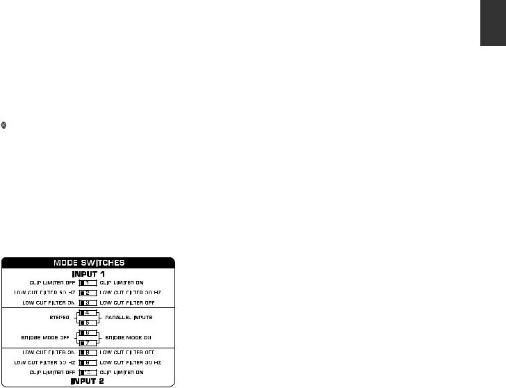
2.3 Configuration switches (MODE SWITCHES)
5
2.3.2 Input filter
The LF (high-pass) filter removes frequencies below 30 and
50 Hz respectively. The reproduction of the signal’s bass portion is thus optimized, since ultra-low, distracting frequencies are eliminated, and more power is available for the reproduction of the wanted segment of the signal. Engaging and disengaging the filters is done by using the switches 3 (ch. 1) and 8 (ch. 2).
Switches 2 (ch. 1) and 9 (ch. 2) determine the cut-off frequency.
As long as the filter is disengaged, frequencies below 5 Hz are cut to prevent damage.
You should set up the filters so they best suit the frequency response of your speakers, since some speakers (e.g. bass reflex speakers) are particularly sensitive to over-excursion below the listed frequency range.
The 50 Hz filter should be engaged when using broadband speakers because the filter provides a moderate amplification in the 100-Hz range, resulting in a fuller sound. The 30 Hz filter is ideally suited for subwoofer operation as well as for broadband cabinets. The “Off” setting should be used only for special applications (e.g. studio applications), in which recognizing and subsequently removing infra-sound is important.
ENGLISH
Fig. 2.3: Dip-switches
2.3.1 Clip limiter
When the input signal connected to your amp is too high, you end up with a distorted output signal. To prevent this, both channels of your EUROPOWER feature a clip limiter that can be engaged or disengaged selectively. The limiters automati- cally recognize distortion and lower amplification until distortion is reduced to a tolerable level. To preserve the dynamic characteristics of the signal when low distortion levels are occurring, the clip limiters function with moderate suppression. Use switches 1 (ch. 1) and 10 (ch. 2) to activate the clip limiters. When using broadband loudspeaker systems, the clip limiter reduces high frequency distortions which occur when an amplifier is overloaded. The drivers are thus protected from being damaged.
 Loading...