


DSP8024
1
E
User´s Manual
Bedienungsanleitung
D
ULTRA-CURVE
®
PRO
DSP8024
Version 1.0 October 1998
www.behringer.de

2
acc. to the Directives
89/336/EWG and 73/23/EWG
We, BEHRINGER INTERNATIONAL GmbH
Hanns-Martin-Schleyer-Straße 4
D - 47877 Willich
Name and address of the manufacturer or the introducer of the product on the market who is established in the EC
herewith take the sole responsibility to confirm that the product:
ULTRA-CURVEPRO DSP8024
Type designation and, if applicable, Article-N
o
which refers to this declaration, is in accordance with the following standards or
standardized documents:
x EN 60065 x EN 61000-3-2
x EN 55020 x EN 61000-3-3
x EN 55013 x EN 55022
The following operation conditions and installation arrangements have to be presumed:
acc. to Operating Manual
B. Nier, President Willich, 01.10.1998
Name, address, date and legally binding signature of the person responsible
EG-Declaration of Conformity
INTERNATIONAL GmbH
3
E
This symbol, wherever it appears, alerts
you to the presence of uninsulated
dangerous voltage inside the enclosure
- voltage that may be sufficient to constitute a risk of shock.
This symbol, wherever it appears, alerts
you to important operating and maintenance instructions in the accompanying
literature. Read the manual.
SAFETY INSTRUCTIONS
CAUTION: To reduce the risk of electrical shock, do not remove
the cover (or back). No user serviceable parts inside;
refer servicing to qualified personnel.
WARNING: To reduce the risk of fire or electrical shock, do not
expose this appliance to rain or moisture.
DETAILED SAFETY INSTRUCTIONS:
All the safety and operation instructions should be read before the appliance is operated.
Retain Instructions:
The safety and operating instructions should be retained for future reference.
Heed Warnings:
All warnings on the appliance and in the operating instructions should be adhered to.
Follow instructions:
All operation and user instructions should be followed.
Water and Moisture:
The appliance should not be used near water (e.g. near a bathtub, washbowl, kitchen sink, laundry tub, in a wet
basement, or near a swimming pool etc.).
Ventilation:
The appliance should be situated so that its location or position does not interfere with its proper ventilation.
For example, the appliance should not be situated on a bed, sofa rug, or similar surface that may block the
ventilation openings, or placed in a built-in installation, such as a bookcase or cabinet that may impede the
flow of air through the ventilation openings.
Heat:
The appliance should be situated away from heat sources such as radiators, heat registers, stoves, or other
appliance (including amplifiers) that produce heat.
Power Source:
The appliance should be connected to a power supply only of the type described in the operating instructions
or as marked on the appliance.
Grounding or Polarization:
Precautions should be taken so that the grounding or polarization means of an appliance is not defeated.
Power-Cord Protection:
Power supply cords should be routed so that they are not likely to be walked on or pinched by items placed
upon or against them, paying particular attention to cords and plugs, convenience receptacles and the point
where they exit from the appliance.
Cleaning:
The appliance should be cleaned only as recommended by the manufacturer.
Non-use Periods:
The power cord of the appliance should be unplugged from the outlet when left unused for a long period of time.
Object and Liquid Entry:
Care should be taken so that objects do not fall and liquids are not spilled into the enclosure through openings.
Damage Requiring Service:
The appliance should be serviced by qualified service personnel when:
- The power supply cord or the plug has been damaged; or
- Objects have fallen, or liquid has been spilled into the appliance; or
- The appliance has been exposed to rain; or
- The appliance does not appear to operate normally or exhibits a marked change in performance; or
- The appliance has been dropped, or the enclosure damaged.
Servicing:
The user should not attempt to service the appliance beyond that is described in the Operating Instructions. All
other servicing should be referred to qualified service personnel.

4
DSP8024
ULTRA-CURVEPRO
Digital Stereo Mainframe powered by two 24-bit High-Speed Signal Processors
s
High-end Crystal 24-bit AD/DA converters for ultra-high dynamic range and resolution
s
Open-ended & future-proof architecture allows for future Software Upgrades
s
Ultra-musical Dual 31-band Graphic Equalizer with True Frequency Response characteristics
s
Low / high / bell shelving tool with variable slope (3 - 30 dB)
s
Real Time Analyzer with peak hold, variable integration, cursor read-out and 10 user-memories
s
Automatic Room Equalization using mic input and internal noise generator
s
Additional 6 bands of fully Parametric Equalizer / Notch Filter with up to 1/60th octave bandwidth
s
Integral fully automatic FEEDBACKDESTROYER with intelligent Signal Analyzer for ultra-fast feedback
suppression
s
Integral digital Brickwall Limiter protects against any clipping and dangerous sound pressure levels
s
Integral digital Noise Gate with BEHRINGER's unique IRC (Interactive Ratio Control)
s
Integral Delay with up to 2.5 seconds delay time selectable in milliseconds, meter and feet
s
Ultra-accurate Level Peak Meter with Peak Hold and selectable Reference Levels (+4 dBu / -10 dBV / Dig
Max)
s
Full MIDI parameter and snapshot control for realtime editing
s
Free EQ-Design software allows for total remote control via PC (download at www.behringer.de)
s
100 User-Memories can be stored under any alphabetic name. Memory backed by a long-life battery
s
Security Key Password can be installed for user selective RTA and EQ memory protection and unattended use
s
EQ and Analyzer curves may be copied, compared, added or subtracted for extreme flexibility
s
Crossfade feature to fade between two settings and Stereo Link facility to synchronize both channels
s
24-bit AES/EBU Interface for digital inputs and outputs at 32, 44.1 and 48kHz (optional)
s
Large High-Resolution LCD Graphic Display with high-contrast LED-backlight
s
Servo-balanced Inputs and Outputs on gold-plated XLR and jack connectors for high signal integrity
s
Relay-controlled hard-bypass with an auto-bypass function during power failure (fail-safe relay)
s
High-quality components and exceptionally rugged construction ensure long life and durability
s
Internal power supply design for professional applications
s Manufactured under the ISO9000 management system

5
E
FOREWORD
Dear Customer,
Welcome to the team of ULTRA-CURVEPRO users and thank you very much for expressing your confidence
in BEHRINGER products by purchasing this unit.
It is one of my most pleasant tasks to write this letter to you, because it is the culmination of many months of
hard work delivered by our engineering team to reach a very ambitious goal: making an outstanding device
better still. The ULTRA-CURVE DSP8000 has for quite a long time been a standard tool used by numerous
studios and P.A. rental companies. The task to improve one of our best-selling products certainly meant a
great deal of responsibility, which we assumed by focusing on you, the discerning user and musician. It also
meant a lot of work and night shifts to accomplish this goal. But it was fun, too. Developing a product usually
brings a lot of people together, and what a great feeling it is when everybody who participated in such a project
can be proud of what we've achieved.
It is our philosophy to share our joy with you, because you are the most important member of the BEHRINGER
family. With your highly competent suggestions for new products you've greatly contributed to shaping our
company and making it successful. In return, we guarantee you uncompromising quality (manufactured under
ISO9000 certified management system) as well as excellent technical and audio properties at an extremely
favorable price. All of this will enable you to fully unfold your creativity without being hampered by budget
constraints.
We are often asked how we can make it to produce such high-grade devices at such unbelievably low prices.
The answer is quite simple: it's you, our customers! Many satisfied customers means large sales volumes
enabling us to get better conditions of purchase for components, etc. Isn't it only fair to pass this benefit back
to you? Because we know that your success is our success, too!
I would like to thank all people whose help on Project ULTRA-CURVEPRO has made it all possible. Everybody has made very personal contributions, starting from the designers of the unit via the many staff members
in our company to you, the user of BEHRINGER products.
My friends, it's been worth the trouble!
Thank you very much,
Uli Behringer

6
TABLE OF CONTENTS
1. INTRODUCTION.....................................................................................................................8
1.1 The design concept ......................................................................................................................... 8
1.2 Before you begin ............................................................................................................................. 8
1.3 Control elements ............................................................................................................................. 9
2. OPERATION .......................................................................................................................... 11
2.1 EQmode .......................................................................................................................................11
2.1.1 Operating the Graphic Equalizer............................................................................................ 11
2.1.2 The Level Meter .................................................................................................................... 12
2.1.3 The FEEDBACK DESTROYER ............................................................................................ 13
2.1.4 Delay ................................................................................................................................... 14
2.1.5 Equalizer editing .................................................................................................................. 14
2.1.6 EQ setup ............................................................................................................................. 16
2.2 Real Time Analyzer ....................................................................................................................... 18
2.2.1 Program administration ........................................................................................................ 18
2.2.2 Toolbox ................................................................................................................................ 19
2.2.3 Choosing a source ............................................................................................................... 19
2.2.4 Decay .................................................................................................................................. 19
2.2.5 RTA setup ............................................................................................................................ 19
2.3 AUTO-Q function ........................................................................................................................... 21
2.4 General setup ............................................................................................................................... 22
3. APPLICATIONS .....................................................................................................................25
3.1 Using the ULTRA-CURVEPRO as a summing EQ in a P.A. ......................................................... 25
3.2 Using the ULTRA-CURVEPRO for monitor EQ purposes ............................................................. 27
3.3 Using the ULTRA-CURVEPRO in the recording studio ............................................................... 28
3.4 The ULTRA-CURVEPRO as part of a keyboard setup .................................................................. 28
3.5 The ULTRA-CURVEPRO in a guitar setup .................................................................................... 29
3.6 The ULTRA-CURVEPRO as an ADC (AES/EBU Option) .............................................................. 29
3.7 The ULTRA-CURVEPRO as a delay unit ...................................................................................... 30
4. TECHNICAL BACKGROUND .............................................................................................. 31
4.1 Audio dynamics ............................................................................................................................ 31
4.1.1 Noise as a physical phenomenon ....................................................................................... 31
4.1.2 Audio dynamics? ................................................................................................................ 32
4.1.3 Compressors/limiters .......................................................................................................... 33
4.1.4 Expanders/noise gates ....................................................................................................... 34
4.2 Digital audio processing ................................................................................................................ 34
4.2.1 The AES/EBU and S/PDIF standards.................................................................................. 35
4.3 True response ............................................................................................................................... 37
4.4 ULTRA-CURVEPRO structure ...................................................................................................... 38
4.4.1 Hardware ............................................................................................................................ 38
4.4.2 EQmode ............................................................................................................................ 39
4.4.3 Real time analyzer mode ....................................................................................................40
5. INSTALLATION ..................................................................................................................... 41
5.1 Rack mounting .............................................................................................................................. 41
5.2 Mains connection .......................................................................................................................... 41
5.3 Audio connections ........................................................................................................................ 41
5.4 Digital audio connections per AES/EBU (Optional) ........................................................................ 43
5.5 MIDI connections .......................................................................................................................... 43

7
E
6. APPENDIX ............................................................................................................................. 43
6.1 Digital I/O ...................................................................................................................................... 43
6.2 Changing the memory protect battery ........................................................................................... 44
6.3 MIDI implementation ..................................................................................................................... 45
6.4 Software........................................................................................................................................ 46
6.4.1 Operating software .............................................................................................................. 46
6.4.2 PC software EQ-Design .....................................................................................................46
6.5 Technical Specifications ................................................................................................................ 50
7. WARRANTY .......................................................................................................................... 53

8
1. INTRODUCTION
The BEHRINGER ULTRA-CURVEPRO is a fully digital sound processing device based on DSPs and 24-bit
A/D and D/A converters. The high speed DSPs are capable of performing any process in fractions of a second,
the only element governing their performance being the software. The enormous flexibility available means that
the ULTRA-CURVEPRO has a range of features greatly exceeding those found in a conventional analog
graphic equalizer, at a price previously unimaginable.
+ The following operational manual will introduce you to the BEHRINGER ULTRA-CURVEPRO
and its various functions. After reading the manual carefully, make sure it is always on hand
for future reference.
1.1 The design concept
The BEHRINGER ULTRA-CURVEPRO is a digital mainframe. This means that after the servo-balanced input
stage the signal is converted to digital and that all processing is done within the digital domain. After processing the signal is then converted back to analog and sent to the servo-balanced outputs. With the digital input /
output option it is possible to connect a digital device to either the input or output or to both in and output.
Processing digitally gives certain advantages. What the unit does only depends on the software that runs the
device and the performance depends on the processing speed and quality of the hardware that the software is
run on. When new ideas and algorithms are developed and become available they can be implemented in the
software. It also means that the ULTRA-CURVEPRO has become more than just a very good graphic equalizer. It also incorporates a full parametric equalizer and several intelligent active functions like the
FEEDBACKDESTROYER, limiter, and noise-gate. It even means that the ULTRA-CURVEPRO can measure
and correct the response of the a system in a room. This gives this digital mainframe possibilities beyond
conventional analog units.
The philosophy behind BEHRINGER products guarantees a no-compromise circuit design and employs the
best choice of components. Top-quality 24-bit AD/DA converters which belong to the best components available owing to its outstanding specifications and excellent sonic characteristics. Two 24-bit DSPs are used as
the heart of the ULTRA-CURVEPRO. These perform the precise calculations needed for the processing of the
complex algorithms. Additionally, the ULTRA-CURVEPRO uses high quality resistors and capacitors with
very tight tolerances, high-grade switches, low-noise operational amplifiers (type 4580) as well other selected
components
The ULTRA-CURVEPRO DSP8024 uses SMD technology (Surface Mounted Device). These subminiature
components known from aerospace technology allow for an extreme packing density, plus the unit's reliability
could be improved. Additionally, the unit is manufactured in compliance with the ISO9000 certified management system.
Fail-safe relays have been incorporated into the design of the BEHRINGER ULTRA-CURVEPRO, which automatically and silently bypass the unit in the event of power supply disconnection or failure. These relays are
also active at switch-on to isolate the ULTRA-CURVEPRO until the power rails have settled, thus preventing
the possibility of a potentially damaging switch-on thump.
1.2 Before you begin
Your BEHRINGER ULTRA-CURVEPRO was carefully packed in the factory and the packaging was designed
to protect the unit from rough handling. Nevertheless, we recommend that you carefully examine the packaging
and its contents for any signs of physical damage, which may have occurred in transit.
+ If the unit is damaged, please do not return it to us, but notify your dealer and the shipping
company immediately, otherwise claims for damage or replacement may not be granted.
Shipping claims must be made by the consignee.
The BEHRINGER ULTRA-CURVEPRO fits into one standard 19" rack unit of space (1 3/4"). Please allow at
least an additional 4" depth for the connectors on the back panel.
+ Be sure that there is enough space around the unit for cooling and please do not place the
ULTRA-CURVEPRO on high temperature devices such as power amplifiers etc. to avoid overheating.
1. INTRODUCTION

9
E
The mains connection of the ULTRA-CURVEPRO is made by using a mains cable and a standard IEC
receptacle. It meets all of the international safety certification requirements. Please make sure that all units
have a proper ground connection.
+ Before you connect your ULTRA-CURVEPRO to the mains, please make sure that your local
voltage matches the voltage required by the unit! (see chapter 5 for details)
+ Please ensure that only qualified persons install and operate the ULTRA-CURVEPRO. During
installation and operation the user must have sufficient electrical contact to earth. Electrostatic charges might affect the operation of the ULTRA-CURVEPRO!
As a standard the audio inputs and outputs on the BEHRINGER ULTRA-CURVEPRO are fully balanced. If
possible, connect the unit to other devices in a balanced configuration to allow for maximum interference
immunity.
1.3 Control elements
Fig. 1.1: The control surface of the ULTRA-CURVEPRO
1
The heart of the front panel is the LED backlighted 240 x 64 active LCD DISPLAY. The control of the
ULTRA-CURVEPRO in centered around the central display. The user interface is for a large part graphical, complemented by four text based setup menus. The function of the Softkeys is displayed right next
to these keys, their function changes to accommodate different features.
2
To the right of the display you will find a LED which registers incoming MIDI messages.
Control of the ULTRA-CURVEPRO is carried out by using three KEY-GROUPS, each consisting of four keys.
On the left of the front panel the keys for operation and bypass are to be found, above each is an associated
status LED.
3
The EQ - KEY. Switches the ULTRA-CURVEPRO into EQUALIZER mode. In this mode, the EQ,
FEEDBACK DESTROYER and DELAY functions may be used.
4
The RTA - KEY. Switches the ULTRA-CURVEPRO into ANALYZER mode. This mode is solely con-
cerned with measuring and signal generation, the sound will not be affected!
5
IN/OUT - KEY. The ULTRA-CURVEPRO can be switched into the signal path (LED is green) or switched
out (Bypass, LED dark). The LED flickering red indicates DSP overflow. This does not necessarily mean
clipping. Flickering starts as soon as an internal overflow in one of the filters occurs,while input and
output levels may be o.k. When this LED lights up often, reduce the input level or the
ULTRA-CURVEPRO's gain level.
6
SETUP - KEY. The SETUP key allows entry into the SETUP menus where all the basic adjustments of
the device are to be found, such as the choice of input source, sample rate, password protection, MIDI
configuration etc. Pressing once will open either the EQ-setup or RTA-setup, depending on the function
of the unit. Holding the key down for two seconds or more will open the general setup windows consisting of a global setup and a MIDI setup window. Pressing the setup key here will toggle between both
general setup windows. You can exit either of the setup menus by pressing the EQ or RTA key.
7
SOFTKEYS.
1. INTRODUCTION

10
To the left of the display four SOFTKEYS, labelled A, B, C and D respectively, are to be found arranged
vertically. Their functions can be defined by the user software and displayed to the immediate right of
each key by the appropriate PICTOGRAM in the display. Each pictogram and its associated functions
will be comprehensively explained in chapter 2. You will find function diagrams for both EQ and RTAmode
as well as a list of all pictograms used next to the back cover.
8
The CURSOR KEYS.
To the right of the display the CURSOR KEYS are to be found. These are used:
1.) to select individual filter frequencies, and the master fader in EQUALIZER mode (horizontal)
2.) to adjust the value of each selected frequency (vertical)
3.) to position the measurement cursor in ANALYZER mode (horizontal)
4.) in both operating modes, to choose the program position (vertical)
5.) to select a field in the SETUP menu (horizontal and vertical)
+ In each case pressing on the opposite key while holding the key being used will accelerate
the operation being carried out.
Fig. 1.2: The back panel layout of the ULTRA-CURVEPRO
9
This is the MAINS CONNECTOR / FUSE HOLDER / VOLTAGE SELECTOR. Before you connect the
unit, please make sure that the displayed voltage corresponds to your Mains supply. Please note that
the AC voltage selection is defined by the position of the Fuse Holder. If you intend to change the
operating voltage, remove the Fuse Holder and twist it by 180 degrees before you reinsert it. Matching
the two markers monitors the selected voltage. Please note that, depending on the mains voltage
supplied to the unit, the correct fuse type and rate must be installed (see chapter 6.4 Technical Specifications). Please use the enclosed mains cable to connect the unit to the mains power supply.
+ Please note that not all appliances can be used with different mains voltage ratings. Please
check the description on the back of the unit and the box.
10
The MAINS SWITCH is to be found above the mains socket. The switch is situated on the backpanel to
make the ULTRA-CURVE tamper proof with unattended use. The unit will bypass on power failure but
cannot be bypassed when a password is set.
11
Please take the time to make a note of the SERIAL NUMBER in the space provided on the enclosed
Warranty Registration Card. Put the instruction manual in a safe place and return the completed
Warranty Registration Card to us within 8 days of purchase, making sure that the dealer stamp
has been acquired.
12
AES/EBU IN and AES/EBU OUT. These are the ULTRA-CURVEPRO's Digital Input and Output (optional). The analog output signal is also present at the (analog) outputs when the digital out is used.
Both signals can be used in parallel.
13
These are the ULTRA-CURVEPRO's MIDI connectors (MIDI OUT / THROUGH / IN). Via these connectors total remote control is possible.
14
ANALOG OUTPUTS. These are the ULTRA-CURVEPRO's analog outputs. When the AES/EBU option
is installed the analog output will still be present at these outputs, so that both analog and digital out can
be used in parallel.
15
These are the ULTRA-CURVEPRO's ANALOG INPUTS.
16
This is the MIC INPUT socket for the Reference Microphone.
1. INTRODUCTION
11
E
2. OPERATION
The following chapter will familiarize you with the operation of your BEHRINGER ULTRA-CURVEPRO. It will
provide you with the basic understanding of how to obtain the desired results and should encourage you to
experiment with the DSP8024. Please bear in mind that the technical specifications of a unit may determine
its limits, but the skill of the audio engineer determines how much use can be made from it. So do not hesitate
to play with the unit, just like a musician does with an instrument, in order to explore the full functionality of
your ULTRA-CURVEPRO.
The BEHRINGER ULTRA-CURVEPRO is a flexible, universally applicable sound processing and measurement device, whose operations may be divided into two basic areas; Signal Processor (Equalizer, Limiter) or
Real Time Analyzer (RTA).
+ For this reason, you always operate in either EQ or RTAmode. Simultaneous operation of
both is not possible!
When the ULTRA-CURVEPRO is switched from one mode to the other, the outputs will be briefly muted.
2.1 EQmode
2.1.1 Operating the Graphic Equalizer
Upon switching on the ULTRA-CURVEPRO you will be presented either the main EQUALIZER (EQ), or
ANALYZER (RTA) window. By pressing the EQ or RTA key, the ULTRA-CURVEPRO will switch from RTAinto EQmode and vice versa.
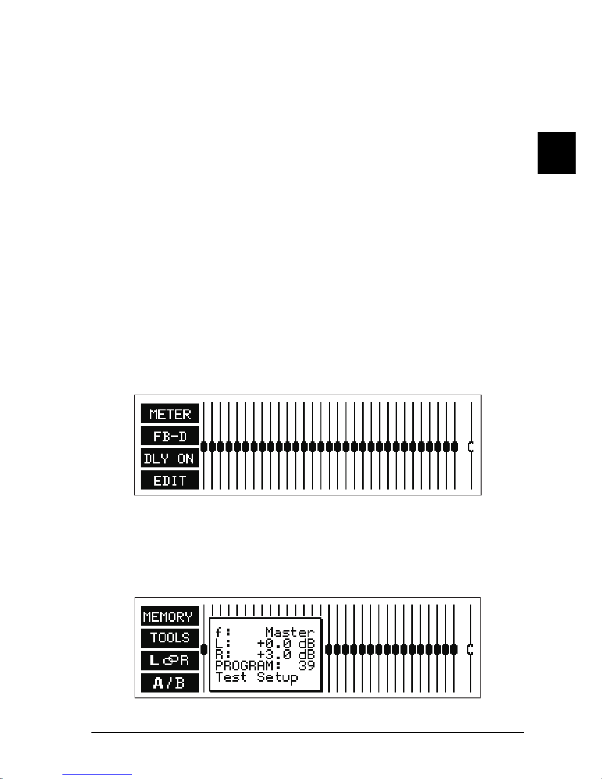
The display shows a 31-band GRAPHIC EQUALIZER, along with, slightly separated on the right hand side, the
main fader for overall level control. On the left are the pictograms for the softkeys, which are used to open the
sub-menus.
Fig. 2.1: Main EQ window of the ULTRA-CURVEPRO
The selected controller is shown highlighted in the display. The vertical cursor keys are used to adjust levels,
the horizontal keys to select the controller to be adjusted. When you depress a cursor key, an information
window appears showing the selected frequency, the level of boost or attenuation applied to each of the two
channels, as well as the program number and program name.
Fig. 2.2: Graphic EQ information window
2. OPERATION

12
The information window disappears after 4 seconds if no further key has been pressed. Depressing a key
once will result in a parameter changing by the smallest applicable increment. The adjacent fader will be
selected, or a level will be adjusted by 0.5dB. Depressing and holding the cursor key results in a continuous
change in the parameter. The rate of change remains constant. You can increase the rate of change by first
depressing and holding the key used to change the relevant parameter, and then, still holding the first key,
depress the one opposite.
2.1.2 The Level Meter
By pressing softkey A you leave the main EQ window and access the menu to display levels.
Fig. 2.3: LEVEL METER display
You can use the LEVEL METER to control the input and output levels of the ULTRA-CURVEPRO. The
bargraph display controls the effective RMS level (massive parts of the bars), and the peak level (checkered
tips of the bars), both simultaneously. To save your eyes, the release time of the peak display is 20dB/s. The
maximum levels are memorized and numerically displayed.
When the limiter threshold is exceeded, the indication LIMIT will appear in the level meter display to indicate
that the limiter is attenuating the output. The limiter is switched on by entering a limiter threshold in the EQsetup menu (chapter 2.1.6). The limiter of the ULTRA-CURVEPRO looks ahead a couple of samples to
anticipate audio dynamics. This enables a smooth and, within obvious limits, unobtrusive limiter operation.
Therefore the LIMIT indication is shown immediately when the limiter engages, even before the gain reduction
becomes noticeable.
With key A you leave the LEVEL METER, and return to the main EQ window. With key B you
erase the maximum levels from the memory. With key C / you switch the display from the
ULTRA-CURVEPRO input and output. With key D you can choose between three different tables of reference
levels.
The 0 dB point is indicated by a bold marker, while at the same time, the numerical display changes.
refers to the digital peak level. THIS LEVEL MAY NOT, UNDER ANY CIRCUMSTANCES, BE EXCEEDED!
This will result in a very noticeable form of distortion, which occurs much faster, and sounds very much more
unpleasant, than the familiar distortion associated with analog devices.
refers to the operating level found in professional audio equipment (analog inputs and outputs of the
ULTRA-CURVEPRO). refers to the operating level found in homerecording and domestic audio equipment, a typical example being tape recorders with RCA connectors. When setting the ULTRA-CURVEPROs
internal level, or when using the optional AES/EBU interface, the peak level display of the Dig Max scale is
the ONLY one to use.
The +4 dBu and -
dBV scales serve to monitor the analog inputs and outputs of the ULTRA-CURVEPRO. Please note that the
RMS level will usually be quoted in the technical specifications of analog devices for example, for the input
sensitivity of power amplifiers. The effective level always lies below the peak level. The difference between
them depends on the signal characteristics for a static sine wave, the effective level is about 3 dB below the
peak level. For a dynamic signal the difference is in the region of 8 dB.
The Dig Max level is, of course, related to the analog input and output levels, as 0 dB Dig Max corresponds to
the maximum output level of the ULTRA-CURVEPRO. The following example, using a sine wave at maximum
2. OPERATION

13
E
amplitude, clearly illustrates the relationship between the various scales:
Scale
RMS Peak
Dig Max -3 dB 0 dB
+4 dBu +9 dB +12 dB
10 dBV +21 dB +24 dB
Maximum Level
Reading
+16 dBu / +14 dBV
Tab. 2.1: Level meter scale correlation
As can be seen from the above table, the ULTRA-CURVEPROs maximum analog output level is +16 dBu, or
+14 dBV. The ULTRA-CURVEPROs analog inputs can handle signals of up to +21 dBu, but it is important to
remember that, in case of such high input levels, the digital LIMITER may operate if the level in the EQUALIZER
is not appropriately lowered. Please refer to the operation of the digital LIMITER explained in section 2.1.6.
2.1.3 The FEEDBACK DESTROYER
By pressing softkey B you leave the main EQ window and go into the FEEDBACK DESTROYER / PEQ menu.
Fig. 2.4: FEEDBACK DESTROYER display
The display will show the current settings for all 6 of the ULTRA-CURVEPRO Parametric Equalizers (selected
frequency, bandwidth and degree of boost or attenuation). Additionally it will show whether the parameters are
fixed, or are set for automatic search, to function as the FEEDBACK DESTROYER. The following modes are
possible:
Code Mode
AUT Automatic Search
SGL Single Shot Search
LCK Locked
OFF Gain set to 0 dB
PAR Parametric Equalizer
Tab. 2.2: FEEDBACKDESTROYER filter modes
Auto search means that the audio signal is continuously examined for signs of feedback. If feedback is
detected, the ULTRA-CURVEPRO will assign an appropriate filter to the relevant frequency and apply narrow
band attenuation, also known as a Notch Filter. The parameters which have been used will be continuously
displayed. The next feedback will be dealt with by the next available filter. When all the filters have been used,
and feedback still occurs, the filter used for the first, or oldest frequency will be released to deal with the newest
one. If feedback occurs very close to a frequency already being treated, or reappears at a frequency to which
a filter has already been applied, the filter already in use will have its parameters changed to deal with the new
problem, i.e. the bandwidth will be widened, or the attenuation increased.
2. OPERATION

14
In single shot mode the filter will not release a setting which has been achieved, this is particularly useful with
problems at fixed frequencies like turntable resonances and fixed microphone and monitor positions. If feedback is detected the filter will deal with that frequency and the status of that filter will change to locked (LCK).
It will only widen its bandwidth or increase the attenuation but it will not release that frequency to deal with a
new feedback frequency. Please note the application example in section 3.2.
When used as a parametric equalizer all parameters can be set manually. It is also possible to change an
achieved FEEDBACKDESTROYER setting to PAR to fixate the setting so that the filter will not be changed
further.
When set to OFF the gain will be set to 0 dB so that the filter has no influence at all.
+ Be careful with setting an achieved feedback filter to OFF as this may cause a suppressed
feedback to become audible again!
The FEEDBACKDESTROYER remains active in all (graphic) EQ-menus. In the setup menus as well as the
level meter menu the parameters of all filters are fixed. The FEEDBACKDESTROYER stops searching in
these menus.
2.1.4 Delay
By pressing softkey C / the built in signal DELAY can be switched on or off. The display shows the
current status: = switched off, = switched on, signal will be delayed by the preset numerical value.
You can set the DELAY time in the EQ SETUP menu (see chapter 2.1.6). Among its many uses, it can be
used to compensate for time path differences between two sets of loudspeakers set at different distances to
the listener. See chapter 3 for an application example.
2.1.5 Equalizer editing
By pressing softkey D or by using a cursor key, the function of the softkeys is changed, and this is
highlighted by a new set of pictograms. With these, you can access either further sub-menus with their own
functions, or carry out important switching functions. We remind you to the function diagrams next to the back
cover. They give you an overview of the way all the menus and sub menus are inserted into one other, in EQ and
RTAmode respectively.
Fig. 2.5: EQ EDITING display
You can now enter
with key A the Program Administration to store, load and name settings
with key B the Tools menu,
with key C / the Channel Switching (STEREOLINK ON),
/ the Channel Switching (STEREOLINK OFF) and
with key D / the Comparison Functions.
Program administration
A PROGRAM contains the settings for the GRAPHIC EQUALIZER, the PARAMETRIC FILTERS and the
optional DELAY. Softkey A allows access to further sub menus which are used to organize the Program
Administration.
A) Loading programs
2. OPERATION

15
E
Softkey A This shows, in the equalizer display, the same information window as shown when operating
a fader. However, in contrast to normal equalizer operation, you cannot change the level with the cursor key,
instead you can select a new program. You can confirm this with or cancel it with . In both cases
you are then returned back to the EDIT menu.
When you select a program to be loaded, the ULTRA-CURVEPRO may behave differently depending on
whether a crossfadetime has been set in the SETUP menu. The CROSSFADE function causes a soft or
gradual transition from one program when switching into another. This helps prevent any clicks or other noises,
which can be caused by very sudden changes to a program. The faders are seen to creep to their new positions
on the display. You may choose the time taken for this to occur, from 0 to 15 seconds being allowed.
CROSSFADE OFF = 0 (s): as you step through the programs displayed, they will be loaded and you can then
hear the effect they make (useful to try out different settings).
CROSSFADE ON = 1 - 15 (s): the chosen program will be executed only upon confirmation. starts the
crossfade between old and new programs (this is best used when you know the specific program which you
wish to use). In this sub-menu you can change channels at any time with the C / softkey.
Using softkey D you can reset all the current ULTRA-CURVEPRO settings - the Graphic Equalizer, the
Parametric Filters (also in FEEDBACKDESTROYER mode) and the DELAY - to zero. You will first be
presented with the question CLEAR PROGRAM IN MEMORY? which can be confirmed with . By using
you can stop at this point and leave the settings as they are.
We recommend that you make use of this feature whenever you have something completely new to do and
have to start from scratch. This way, you can carry on without the danger that maybe an old
FEEDBACKDESTROYER setting is in the place which could cause problems. In any case it is the quickest
and most convenient way to reset all the parametric filters.
B) Saving programs
Softkey B The procedure of saving a program is analogous to that of loading one. The memory location
is selected with the vertical cursor keys, is confirmed with or cancelled with . If a program location
is already occupied, the warning OVERWRITE PROGRAM? will appear. Pressing once more allows you
to confirm the save, means it does not take place, and the program already in place remains undisturbed. When is pressed a window is opened where the name can be entered when an empty memory
place is used or the previous name can be edited.
Important to note here is that program names can have a maximum of 12 characters. You will see a window in
the equalizer display, showing the available characters. Choose the character you require with the cursor key,
which is to be found in the part of the name field highlighted by blinking. You can change position using the
arrows keys / , removes all characters. Having completed the name you wish to use,
pressing returns you to the EDIT menu.
+ When naming, remember it is always the program resident in memory which you are naming.
If you want to rename a stored program, you must first load it into memory.
D) Additive and subtractive editing of programs. Load firstly the program to which you wish to add or subtract
another program, then press Softkey D . In the pictograms either a plus or a minus will appear or
disappear. If you now wish to load and add a program onto the one already in memory, press softkey D until a
+ appears. Using key A , you can now choose and load a further program, which will be added to the one
already in memory. The same procedures apply for subtraction and saving.
+ When loading and subtracting the program that is taken from memory is subtracted from the
current program. When storing and subtracting the current program is subtracted from the one
in memory.
+ Additive and subtractive editing only applies to the graphical equalizer. The parametric equal-
izer settings remain intact.
The tools menu
Using softkey B you can enter the sub-menus which contain a number of tools to edit the graphic
equalizer. They affect the selected channel, except when STEREOLINK is ON (see section 2.1.6) when they
effect both channels.
+ The parametric filter settings will not be changed by use of the toolbox. They may only be
edited in EQ SETUP (see section 2.1.6). A) Resetting the graphic EQ
A) Resetting all faders to zero.
2. OPERATION

16
Softkey A . All the graphic equalizer faders including the master fader will be reset to zero. Having
carried this out, you can confirm the changes made with or you can cancel them with . In either
case, you will be then returned to the EDIT menu. With softkey C / or / respectively,
you can check the status of each channel on the display, before confirming the changes as mentioned
above. While doing this, you cannot make any other changes.
B) Inverting the current settings
Softkey B This causes the levels of all the graphic faders, with the exception of the master fader, to
invert. I.e. a value of +5 becomes -5, -2 becomes +2 etc. This edit can be confirmed as above.
C) Copying the current setting to the other channel
Softkey C / The current setting will be copied to the other channel. Confirmation as above.
D) The shelving tool
Softkey D You will be presented with the shelving menu. By repeatedly pressing softkey D you can
switch between three different tools:
creates a shelving curve below the selected frequency,
creates a shelving curve above the selected frequency,
creates a peaking response centered on the selected frequency.
You can use the horizontal cursor keys to choose the frequency at which or from which the tool will operate.
You can use the vertical cursor keys to adjust the level. The shelving function is always superimposed upon
any graphic or parametric curve already existing in RAM. In other words, the relative levels of adjacent frequency bands are maintained, while the overall slope is altered. You can create curves with varying slopes, the
slope can be adjusted, in 3 dB steps, from a slope of 6 to 30 dB per octave.
Having confirmed the edit with , the ULTRA-CURVEPRO will leave the shelving mode, and return to the
EDIT menu. By pressing the settings made in the shelving menu will be cancelled, and you return to the
EDIT menu.
Channel switching
In the EDIT menu, you can switch back and forth between the two channels, using softkey C. The pictogram for
softkey C will show you which channel is active, and whether or not the channels are connected to each other
via the STEREOLINK function.
Left channel, STEREOLINK ON
Right channel, STEREOLINK ON
Left channel, STEREOLINK OFF
Right channel, STEREOLINK OFF.
Comparison Functions
Softkey D (A highlighted) or (B highlighted) allows you to compare the current setting with the
settings pertaining to the program as it was loaded. (A highlighted) denotes the program as it was on
loading. (B highlighted) denotes the most recent setting. If you are not satisfied with the new setting, you
can return to (A highlighted), and from there you can start again. Once you start to edit, the pictogram
will change to (B highlighted), immediately showing the new status of the program. Upon loading a new
program, (neither A nor B highlighted) will be shown, indicating the not-yet-edited status of the program.
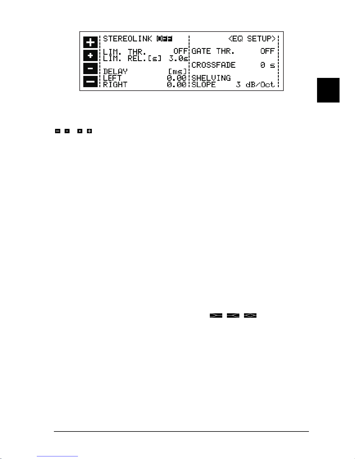
2.1.6 EQ setup
You can access the EQ SETUP menu by pressing the SETUP key while the ULTRA-CURVEPRO is in
EQmode. The EQ SETUP window appears in the display and the LED above the SETUP key starts to blink.
2. OPERATION
17
E
Fig. 2.6: EQ SETUP window
You can use the cursor key to choose either the value or the condition to be changed. The active edit field will
be highlighted by being displayed inverted. You can change status or value by using the softkeys marked
/ or / respectively.
STEREOLINK
ON
The intelligent STEREOLINK function links the two channels, forming a stereo pair, in which all adjustments
made have an equal, simultaneous effect on both channels. It is important to understand that this also applies
when the two channels have different response curves set! The edits performed will make adjustments of equal
value, independent of the original settings. For example: right channel, fader 4 was at +3, increasing 5 dB bring
it to +8. Left channel, fader was at -4. It will be moved to +1 (in other words, the incremental changes are the
same on both channels, but the absolute settings may still differ from each other). A further point to watch out
for is the situation where a fader on one channel has been raised by a value which will take the corresponding
fader on the other, linked channel above the maximum boost which the ULTRA-CURVEPRO is capable of
making, namely 16 dB. Because this is not possible, all the other faders will be automatically attenuated by
the appropriate amount, and the master channel fader will be raised in compensation, in order to achieve the
desired frequency response.
OFF
switches off the channel link. The two channels can now be set fully independent of each other.
CROSSFADE
The CROSSFADE function causes a soft or gradual transition from one program when switching into another.
This helps prevent any clicks or other noises, which can be caused by very sudden changes to a program. The
faders are seen to creep to their new positions on the display. You may choose the time taken for this to occur,
from 0 to 15 seconds being allowed. Please note that a setting of 0 seconds results in a hard switch over,
possibly causing the noises mentioned above.
SHELVING SLOPE
This is a tool which you can use to easily add high shelving, low shelving and bell-shaped response curves to
the Graphic Equalizer. The pictograms representing this tool are / / (see section 2.1.5 on
previous page).
LIMIT THRESHOLD
The ULTRA-CURVEPRO has an integrated DIGITAL LIMITER to protect against overloading and resulting
distortion. Its Attack Time is zero, in other words, it reacts in advance. This way it acts as a real brickwall
and can be used in combination with the security password to create a absolute limiter to prevent noise
pollution.
The operating threshold of the LIMITER can be set, in 1dB steps, anywhere from 0dB down to -36dB. The
levels given in dB are relative to the maximum output signal (Dig Max) of the ULTRA-CURVEPRO (0 dB Dig
Max equates to +16 dBu or +14dBV). Additionally, you can deactivate the LIMITER by choosing the setting
OFF.
LIMIT RELEASE
When the signal falls below the limiter threshold, the gain reduction is returned to zero. The rate of change is
governed by a time constant (release time) which can be defined between 0.5 and 5 seconds
2. OPERATION
 Loading...