


 Loading...
User Manual
SHARK FBQ100
Automatic Feedback Destroyer with Integrated Microphone Preamp, Delay Line, Noise Gate and Compressor

2 |
SHARK FBQ100 User Manual |
|
Table of Contents |
|
|
Thank you........................................................................ |
2 |
|
Important Safety Instructions....................................... |
3 |
|
Legal Disclaimer.............................................................. |
3 |
|
Limited warranty............................................................ |
3 |
|
1. Introduction................................................................ |
4 |
|
|
1.1 The concept........................................................................... |
4 |
|
1.2 Before you begin................................................................. |
4 |
|
1.3 Control elements................................................................. |
4 |
2. Applications................................................................ |
6 |
|
|
2.1 Wiring the FBQ100: general remarks............................ |
6 |
|
2.1.1 Connection between microphone |
|
|
and mixing console................................................................. |
6 |
|
2.1.2 Connection between line-level source |
|
|
and mixing console................................................................. |
6 |
|
2.1.3 Connection between mixing console |
|
|
and power amplifier................................................................ |
6 |
|
2.1.4 The SHARK used in the monitor path.................... |
6 |
|
2.1.5 The SHARK used in single channels |
|
|
and subgroups.......................................................................... |
7 |
|
2.1.6 Automatic “tuning in” of P.A. and |
|
|
monitor systems....................................................................... |
7 |
|
2.2 The feedback destroyer in the SHARK......................... |
7 |
|
2.3 The integrated delay.......................................................... |
7 |
|
2.4 The noise gate function.................................................... |
8 |
|
2.5 The low cut filter in the SHARK...................................... |
8 |
|
2.6 The compressor function................................................. |
8 |
3. Installation.................................................................. |
8 |
|
|
3.1 Audio connections.............................................................. |
8 |
4. Specifications............................................................. |
9 |
|
5. Rackmount (Optional)............................................. |
10 |
|
Thank you
Thank you very much for expressing your confidence in BEHRINGER products by purchasing the SHARK FBQ100.
3 SHARK FBQ100 User Manual
Important Safety
Instructions
Terminals marked with this symbol carry electrical current of sufficient magnitude to constitute risk of electric shock.
Use only high-quality professional speaker cables with ¼" TS or twist-locking plugs pre-installed. All other installation or modification should be performed only by qualified personnel.
This symbol, wherever it appears,
alerts you to the presence of uninsulated dangerous voltage inside the
enclosure - voltage that may be sufficient to constitute a risk of shock.
This symbol, wherever it appears, alerts you to important operating and maintenance instructions in the
accompanying literature. Please read the manual.
Caution
To reduce the risk of electric shock, do not remove the top cover (or the rear section).
No user serviceable parts inside. Refer servicing to qualified personnel.
Caution
To reduce the risk of fire or electric shock, do not expose this appliance to rain and moisture. The apparatus shall not be exposed to dripping
or splashing liquids and no objects filled with liquids, such as vases, shall be placed on the apparatus.
Caution
These service instructions are for use by qualified service personnel only.
To reduce the risk of electric shock do not perform any servicing other than that contained in the operation instructions. Repairs have to be performed by qualified service personnel.
1.Read these instructions.
2.Keep these instructions.
3.Heed all warnings.
4.Follow all instructions.
5.Do not use this apparatus near water.
6.Clean only with dry cloth.
7.Do not block any ventilation openings. Install in accordance with the manufacturer’s instructions.
8.Do not install near any heat sources such as radiators, heat registers, stoves, or other apparatus (including amplifiers) that produce heat.
9.Do not defeat the safety purpose of the polarized or grounding-type plug. A polarized plug has two blades with one wider than the other. A grounding-type plug has two blades and a third grounding prong. The wide
blade or the third prong are provided for your safety. If the provided plug does not fit into your outlet, consult an electrician for replacement of the obsolete outlet.
10.Protect the power cord from being walked on or pinched particularly at plugs, convenience receptacles, and the point where they exit from the apparatus.
11.Use only attachments/accessories specified by
the manufacturer.
12. Use only with the cart, stand, tripod, bracket,
or table specified by the
manufacturer, or sold with the apparatus. When a cart is used, use caution when
moving the cart/apparatus combination to avoid
injury from tip-over.
13.Unplug this apparatus during lightning storms or when unused for long periods of time.
14.Refer all servicing to qualified service personnel. Servicing is required when the apparatus has been damaged in any way, such as power supply cord or plug is damaged, liquid has been spilled or objects have fallen into the apparatus, the apparatus has been exposed
to rain or moisture, does not operate normally, or has been dropped.
15.The apparatus shall be connected to a MAINS socket outlet with a protective earthing connection.
16.Where the MAINS plug or an appliance coupler is used as the disconnect device, the disconnect device shall remain readily operable.
LEGAL DISCLAIMER
TECHNICAL SPECIFICATIONS AND APPEARANCES ARE SUBJECT TO CHANGE WITHOUT NOTICE AND ACCURACY IS NOT GUARANTEED. BEHRINGER, KLARK TEKNIK, MIDAS, BUGERA, AND TURBOSOUND
ARE PART OF THE MUSIC GROUP (MUSIC-GROUP.COM). ALL TRADEMARKS ARE THE PROPERTY OF THEIR RESPECTIVE OWNERS. MUSIC GROUP ACCEPTS NO LIABILITY FOR ANY LOSS WHICH MAY BE SUFFERED BY ANY PERSON WHO RELIES EITHER WHOLLY OR
IN PART UPON ANY DESCRIPTION, PHOTOGRAPH OR STATEMENT CONTAINED HEREIN. COLORS AND
SPECIFICATIONS MAY VARY FROM ACTUAL PRODUCT. MUSIC GROUP PRODUCTS ARE SOLD THROUGH AUTHORIZED FULLFILLERS AND RESELLERS ONLY. FULLFILLERS AND RESELLERS ARE NOT AGENTS OF MUSIC GROUP AND HAVE ABSOLUTELY NO AUTHORITY
TO BIND MUSIC GROUP BY ANY EXPRESS OR IMPLIED
UNDERTAKING OR REPRESENTATION. THIS MANUAL IS COPYRIGHTED. NO PART OF THIS MANUAL MAY BE REPRODUCED OR TRANSMITTED IN ANY FORM OR BY ANY MEANS, ELECTRONIC OR MECHANICAL,
INCLUDING PHOTOCOPYING AND RECORDING OF ANY KIND, FOR ANY PURPOSE, WITHOUT THE EXPRESS WRITTEN PERMISSION OF MUSIC GROUP IP LTD.
ALL RIGHTS RESERVED.
© 2013 MUSIC Group IP Ltd.
Trident Chambers, Wickhams Cay, P.O. Box 146, Road Town, Tortola, British Virgin Islands
LIMITED WARRANTY
For the applicable warranty terms and conditions and additional information regarding MUSIC Group’s
Limited Warranty, please see complete details online at www.music-group.com/warranty.
4SHARK FBQ100 User Manual
1.Introduction
1.1 The concept
With the SHARK FBQ100 you purchased a device that combines an automatic Feedback Destroyer using the ingenious search algorithms of our FEEDBACK DESTROYER FBQ1000, a variable Delay Line (adjustable in msec, feet and meter), a ULN (Ultra-Low Noise) microphone pre-amp with Phantom Power, an automatic Noise Gate, a variable Low Cut filter and a Compressor—all in one ultra-rugged and compact case. Still, the SHARK can be operated intuitively and expanded to a multi-channel system using another four SHARKs and
an optionally available 19" rack mount kit. The SHARK’s 24-bit A/D and D/A converters guarantee a precise reproduction of your program material.
High volume levels and the use of ever more sophisticated monitoring systems with a multitude of speaker cabinets have led to a greater potential risk of feedback loops in sound reinforcement systems. So far, audio engineers
have been using conventional 1/3-octave equalizers to suppress unwanted feedback. However, the individual filters of such an EQ, with their relatively wide bandwidth, have quite an impact on the sound image. With the BEHRINGER SHARK (minimum bandwidth: 1/60 of an octave) you are now free to either choose the trial and error method to suppress feedback with graphic equalizers, or to assign this task to the FBQ100, so that you can give your music your undivided attention. Using extremely narrow-bandwidth filters, the SHARK FBQ100 eliminates only unwanted feedback, without affecting your music.
Speaker Box
Microphone |
|
|
|
|
|
|
|
|
|
|
|
|
|
|
|
|
|
|
|
|
|
|
|
|
|
|
|
|
|
|
|
|
|
|
|
|
|
|
|
|
|
|
|
|
|
|
|
|
|
|
|
|
|
|
|
|
|
|
|
|
|
|
|
|
|
|
|
|
|
|
|
|
|
|
|
|
|
|
|
|
|
|
|
|
|
|
|
|
|
|
|
|
|
|
|
|
|
|
|
|
|
|
|
|
|
|
|
|
|
|
|
|
|
|
|
|
|
|
|
|
|
|
|
|
|
|
|
|
|
|
|
|
|
|
|
|
|
|
|
|
|
|
|
|
|
|
|
|
|
|
|
|
|
|
|
Mixing Console |
|
|
|
|
|
|
|
|
|
|
|
|
Power Amp |
|||||||||||||||||
Fig. 1.1: Typical feedback loop
1.2 Before you begin
Your SHARK was carefully packed in the factory and the packaging is designed to protect the unit from rough handling. Nevertheless, we recommend that you carefully examine the carton and its contents for any signs of physical damage, which may have occurred during transit.
◊If the unit is damaged, please do not return it to BEHRINGER, but notify your dealer and the shipping company immediately, otherwise claims for damage or replacement may not be granted. Shipping claims must be made by the consignee.
The optionally available rack mount kit allows you to mount your BEHRINGER SHARK in a standard 19" rack, together with another four SHARKs. The rack mount kit requires 2U of rack space.
Be sure that there is enough air space around the unit for cooling and please do not place the SHARK on high-temperature devices such as power amps, etc. to avoid overheating.
Please use the enclosed power supply to connect the unit to the mains. The supply complies with all applicable safety standards.
◊Please note that all units must be grounded properly. For your own safety, you should never remove any ground connectors from electrical devices or power cords or render them inoperative.
Further information can be found in chapter 3 “Installation”.
As a standard the audio inputs and outputs of the BEHRINGER SHARK FBQ100 are fully balanced. If possible, connect the unit to other devices in a balanced configuration to allow for maximum interference immunity. The automatic servo function detects unbalanced connections and compensates the level difference automatically (6 dB correction).
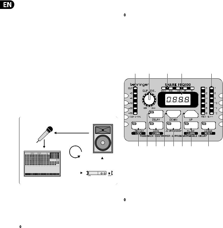
1.3 Control elements
(1) |
(2) |
(3) |
(4) |
(5) |
(9) |
(6) |
(10) |
(7) |
(11) |
(8) |
(12) |
(13) |
Fig. 1.2: Front panel control elements of the FBQ100
(1)The CLIP LEVEL METER shows you whether or not the digital circuitry is driven correctly. Any corrections can be made with the CLIP LEVEL control
(2). Be sure that the CLIP LED won’t light up.
(2)The CLIP LEVEL control lets you adapt the internal gain optimally to the digital circuitry. If gain is too high (CLIP LED lights up), raise the CLIP LEVEL value by turning the control to the right (and vice versa). Thus, you can shift the operating level upwards/downwards.
◊The CLIP LEVEL control does not affect the input/output levels,
but adapts the audio signal as optimally as possible to the threshold of the digital circuitry.
(3)These five LEDs symbolize the units of the parameters that can be adjusted on the display (4).
(4)The 4-digit DISPLAY reads the absolute values of the adjusted parameters.
(5)The FB-D FILTER STATUS LEDs display the status of each of the 12 individual filters. The SHARK uses four different filter modes:
• Disabled filters (which can be re-enabled with the ACTIVE button). When a filter is off, its LED is not lit.
• Free filters which automatically search for feedback frequencies and whose activity is shown by a flashing LED.
• Set filters which can be reconfigured as free (searching) filters, when all filters are currently in use.
• Permanently set filters which must be RESET to be reconfigured as free filters.
Once a filter has been set, its LED lights up.
Loading...