


User Manual
ULTRAGRAPH PRO FBQ6200/FBQ3102/FBQ1502
Audiophile 31-Band and 15-Band Stereo Graphic Equalizer with FBQ Feedback Detection System

2 ULTRAGRAPH PRO FBQ6200/FBQ3102/FBQ1502 User Manual
Table of Contents |
|
Thank you........................................................................ |
2 |
Important Safety Instructions....................................... |
3 |
Legal Disclaimer.............................................................. |
3 |
Limited warranty............................................................ |
3 |
1. Introduction................................................................ |
4 |
1.1 Before you get started....................................................... |
4 |
1.1.1 Shipment........................................................................... |
4 |
1.1.2 Initial operation.............................................................. |
4 |
1.1.3 Warranty........................................................................... |
4 |
1.2 The user’s manual............................................................... |
4 |
2. Control Elements and Connectors............................ |
5 |
2.1 Front panel............................................................................. |
5 |
2.2 Rear panel.............................................................................. |
6 |
2.3 Additional FBQ6200 control elements ....................... |
6 |
2.3.1 Limiter .............................................................................. |
6 |
2.3.2 Noise generator............................................................. |
7 |
2.3.3 Subwoofer section....................................................... |
7 |
3. Application Examples................................................ |
7 |
3.1 Master equalizer in sound |
|
reinforcement systems ............................................................. |
8 |
3.2 Equalizer in the monitor path......................................... |
8 |
3.2.1 Priming a monitor system.......................................... |
9 |
3.3 Using the ULTRAGRAPH PRO in the studio................ |
9 |
3.4 Special sound effects......................................................... |
9 |
4. Installation.................................................................. |
9 |
4.1 Rack mounting .................................................................... |
9 |
4.2 Audio connections............................................................. |
9 |
5. Specifications........................................................... |
10 |
Thank you
Thank you very much for expressing your confidence in our products by purchasing one of our equalizers. This 2-channel high-end equalizer was designed with our experience and know-how in filter technology spanning many years. Our analog and digital equalizers are used the world over in various reputable studios, P.A. systems and radio and TV stations. Just like with the rest of our product line, when we started designing the new ULTRAGRAPH PRO
models, we had put forth uncompromizing demands in terms of controls, sound, technical data and fit-and-finish quality.
3 ULTRAGRAPH PRO FBQ6200/FBQ3102/FBQ1502 User Manual
Important Safety
Instructions
Terminals marked with this symbol carry electrical current of sufficient magnitude to constitute risk of electric shock.
Use only high-quality professional speaker cables with ¼" TS or twist-locking plugs pre-installed. All other installation or modification should be performed only by qualified personnel.
This symbol, wherever it appears,
alerts you to the presence of uninsulated dangerous voltage inside the
enclosure - voltage that may be sufficient to constitute a risk of shock.
This symbol, wherever it appears, alerts you to important operating and maintenance instructions in the
accompanying literature. Please read the manual.
Caution
To reduce the risk of electric shock, do not remove the top cover (or the rear section).
No user serviceable parts inside. Refer servicing to qualified personnel.
Caution
To reduce the risk of fire or electric shock, do not expose this appliance to rain and moisture. The apparatus shall not be exposed to dripping
or splashing liquids and no objects filled with liquids, such as vases, shall be placed on the apparatus.
Caution
These service instructions are for use by qualified service personnel only.
To reduce the risk of electric shock do not perform any servicing other than that contained in the operation instructions. Repairs have to be performed by qualified service personnel.
9.Do not defeat the safety purpose of the polarized or grounding-type plug. A polarized plug has two blades with one wider than the other. A grounding-type plug has two blades and a third grounding prong. The wide
blade or the third prong are provided for your safety. If the provided plug does not fit into your outlet, consult an electrician for replacement of the obsolete outlet.
10.Protect the power cord from being walked on or pinched particularly at plugs, convenience receptacles, and the point where they exit from the apparatus.
11.Use only attachments/accessories specified by
the manufacturer.
12. Use only with the cart, stand, tripod, bracket,
or table specified by the
manufacturer, or sold with the apparatus. When a cart is used, use caution when
moving the cart/apparatus combination to avoid
injury from tip-over.
13.Unplug this apparatus during lightning storms or when unused for long periods of time.
14.Refer all servicing to qualified service personnel. Servicing is required when the apparatus has been damaged in any way, such as power supply cord or plug is damaged, liquid has been spilled or objects have fallen into the apparatus, the apparatus has been exposed
to rain or moisture, does not operate normally, or has been dropped.
15.The apparatus shall be connected to a MAINS socket outlet with a protective earthing connection.
16.Where the MAINS plug or an appliance coupler is used as the disconnect device, the disconnect device shall remain readily operable.
1.Read these instructions.
2.Keep these instructions.
3.Heed all warnings.
4.Follow all instructions.
5.Do not use this apparatus near water.
6.Clean only with dry cloth.
7.Do not block any ventilation openings. Install in accordance with the manufacturer’s instructions.
8.Do not install near any heat sources such as radiators, heat registers, stoves, or other apparatus (including amplifiers) that produce heat.
LEGAL DISCLAIMER
TECHNICAL SPECIFICATIONS AND APPEARANCES ARE SUBJECT TO CHANGE WITHOUT NOTICE AND ACCURACY IS NOT GUARANTEED. BEHRINGER, KLARK TEKNIK, MIDAS, BUGERA, AND TURBOSOUND
ARE PART OF THE MUSIC GROUP (MUSIC-GROUP.COM). ALL TRADEMARKS ARE THE PROPERTY OF THEIR RESPECTIVE OWNERS. MUSIC GROUP ACCEPTS NO LIABILITY FOR ANY LOSS WHICH MAY BE SUFFERED BY ANY PERSON WHO RELIES EITHER WHOLLY OR
IN PART UPON ANY DESCRIPTION, PHOTOGRAPH OR STATEMENT CONTAINED HEREIN. COLORS AND
SPECIFICATIONS MAY VARY FROM ACTUAL PRODUCT. MUSIC GROUP PRODUCTS ARE SOLD THROUGH AUTHORIZED FULLFILLERS AND RESELLERS ONLY. FULLFILLERS AND RESELLERS ARE NOT AGENTS OF MUSIC GROUP AND HAVE ABSOLUTELY NO AUTHORITY
TO BIND MUSIC GROUP BY ANY EXPRESS OR IMPLIED
UNDERTAKING OR REPRESENTATION. THIS MANUAL IS COPYRIGHTED. NO PART OF THIS MANUAL MAY BE REPRODUCED OR TRANSMITTED IN ANY FORM OR BY ANY MEANS, ELECTRONIC OR MECHANICAL,
INCLUDING PHOTOCOPYING AND RECORDING OF ANY KIND, FOR ANY PURPOSE, WITHOUT THE EXPRESS WRITTEN PERMISSION OF MUSIC GROUP IP LTD.
ALL RIGHTS RESERVED.
© 2013 MUSIC Group IP Ltd.
Trident Chambers, Wickhams Cay, P.O. Box 146, Road Town, Tortola, British Virgin Islands
LIMITED WARRANTY
For the applicable warranty terms and conditions and additional information regarding MUSIC Group’s
Limited Warranty, please see complete details online at www.music-group.com/warranty.

4ULTRAGRAPH PRO FBQ6200/FBQ3102/FBQ1502 User Manual
1.Introduction
FBQ Feedback Detection System
The FBQ Feedback Detection System is one of the most outstanding characteristcs of our graphic equalizers. This ingenious circuitry lets you immediately recognize and eliminate feedback frequencies. The FBQ Feedback Detection System
uses the LEDs in the frequency band faders to indicate the critical frequencies. This way, what once used to be a labor-intensive search for feedback frequencies is now an activity that even a child could master.
In normal operation, the fader LEDs indicate frequency ranges with the highest energy levels, therefore replacing a separate audio analyzer. If you keep an eye on the LEDs while you play back your music (or during the sound check before a show), you can easily identify those frequency ranges showing the highest energy levels. Similarly, increased signal levels on individual frequency bands indicate a higher likelihood that feedback may occur.
All three models feature a dedicated subwoofer output with adjustable cut-off frequency. You can also adjust the fader range from ±6 to ±12 dB for each channel independently.
The FBQ1502 requires just one rack space, yet it offers you tons of effective methods for adjusting the sound characteristics, and is ultra-compact and extremely simple to operate.
The FBQ3102 features 31 frequency bands per channel as well as adjustable high-pass and low-pass filters. These filters further augment the adjustability options available to you.
With its integrated limiters, noise generator and the adjustable subwoofer output with signal level display and its 62 lighted 45 mm faders, the FBQ6200 is our top model in this category.
Future-oriented BEHRINGER technology
To assure the highest possible degree of usability, all our equipment is manufactured adhering to the highest quality standards in the audio industry. Your equalizer has been manufactured under ISO9000 certified management system.
Relay-controlled hard bypass
The so-called hard bypass relays were integrated into the development concept of the FBQ6200 and the FBQ3102. These relays assure that your equalizer is automatically switched into bypass mode in the event of loss of power or faulty power delivery. These fail-safe relays also produce a slight delay during powering up in order to avoid dangerous switch-on thumps.
Balanced inputs and outputs
The BEHRINGER ULTRAGRAPH PRO models feature electronic servo-balanced inputs and outputs. The servo function performs automatically, recognizing when unbalanced signals are connected and internally converts the nominal signal level so that no signal level difference between input and output signals occurs (6 dB correction).
◊The following user’s manual is intended to familiarize you with the unit’s control elements, so that you can master all the functions. After having thoroughly read the user’s manual, store it at a safe place for future reference.
1.1 Before you get started
1.1.1 Shipment
The ULTRAGRAPH PRO was carefully packed at the factory to assure secure transport. Should the condition of the cardboard box suggest that damage may have taken place, please inspect the unit immediately and look for physical indications of damage.
◊Damaged units should NEVER be sent directly to us. Please inform the dealer from whom you acquired the unit immediately as well as the transportation company from which you took delivery of the unit. Otherwise, all claims for replacement/repair may be rendered invalid.
1.1.2 Initial operation
Please make sure the unit is provided with sufficient ventilation, and never place the ULTRAGRAPH PRO on top of an amplifier or in the vicinity of a heater to avoid the risk of overheating.
◊Before plugging the unit into a power socket, please make sure you have selected the correct voltage:
The fuse compartment near the power plug socket contains three triangular markings. Two of these triangles are opposite one another. The voltage indicated adjacent to these markings is the voltage to which your unit has been set up, and can be altered by rotating the fuse compartment by 180°.
ATTENTION: This does not apply to export models that were for example manufactured only for use with 120 V!
◊If you alter the unit’s voltage, you must change the fuse accordingly. The correct value of the fuse needed can be found in the
chapter “Specifications”.
◊Faulty fuses must be replaced with fuses of appropriate rating without exception! The correct value of the fuse needed can be found in the chapter “Specifications”.
Power is delivered via the cable provided with the unit. All requiered safety precautions have been adhered to.
◊Please make sure that the unit is grounded at all times. For your own protection, you should never tamper with the grounding of the cable or the unit itself.
1.1.3 Warranty
Please take a few minutes and send us the completely filled out warranty card within 14 days of the date of purchase. You may also register online at behringer.com. The serial number needed for the registration is located on the
rear of the unit. Failure to register your product may void future warranty claims.
1.2 The user’s manual
The user’s manual is designed to give you both an overview of the control elements, as well as detailed information on how to use them. In order to help you understand the links between the controls, we have arranged them in groups according to their function. Should you need detailed information about specific topics not covered in this manual, please visit our website at behringer.com.
For example, additional information about power amps and effects processors is found there.
5ULTRAGRAPH PRO FBQ6200/FBQ3102/FBQ1502 User Manual
2.Control Elements and Connectors
2.1 Front panel
In this chapter we will describe various control elements of your equalizer.
All controls and connectors are explained in detail, and you will also find useful hints on how to best use them. Since the three equalizers in the FBQ series
are fairly similar, let’s start with the control elements of the FBQ1502 and the FBQ3102 that are similar to the control elements found on the FBQ6200.
The FBQ6200 additionally features extra control elements that will be explained in detail later on.
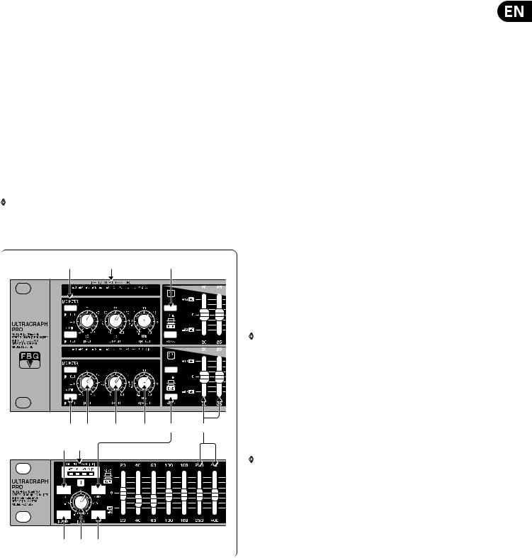
(1)The INPUT/OUTPUT LEVEL METER lets you keep an eye on the signal level in order to avoid distortion. Depending on the position of the I/O METER IN/OUT switch (2), the display shows either the input or the output signal (switch depressed) level. When the signal level reaches roughly +18 dB, that is, 3 dB below clipping starts to occur, the red CLIP LED lights up.
The level meter on the FBQ1502 displays only the output signal level.
◊Attention: extreme frequency boosts in connection with a high input signal level may lead to overdriving your equipment. Should this occur, it is necessary to reduce the input signal level by using the
INPUT control.
Fig. 2.1: Front panel control elements of the FBQ3102 (above) and of the FBQ1502 (below)
(2)The I/O METER IN/OUT switch lets you alternate between displaying the input and the output signal level. When the switch is depressed, the output signal level is shown. The FBQ1502 does not feature this switch.
(3)When you press the FBQ switch, the FBQ feedback detection system is activated. The frequency (or frequencies) that evoke feedback is/are
indicated by means of a lighted fader LED. All other LEDs are toned down. Now, simply lower the respective frequency range somewhat until you eliminate the feedback and the LED no longer lights up.
(4)The AUDIO IN/OUT switch is used to enable or disable the entire equalizer section. The FBQ1502 does this electronically, while the FBQ3102 and the FBQ6200 feature a relay-driven hard bypass function. As long as the switch is not depressed or while the equalizer is not powered up, the inputs and the outputs are directly connected to one another. The AUDIO IN/OUT switch is used to alternate between A and B, i.e. to compare the original unprocessed signal with the processed signal.
(5)The INPUT control is used to adjust the input signal level. You can boost/attenuate the signal level from +15 to -15 dB.
(6)The LOW CUT control is used to adjust the lower cut-off frequency of your ULTRAGRAPH PRO. The high-pass filter (18 dB/oct.) covers the range between
10 and 400 Hz, whereby the filter lets the signal pass through unprocessed, when the control is in the 10 Hz position.
The FBQ1502 features a switchable high-pass filter (LOW CUT) instead of a low cut control, and its cut-off frequency is 25 Hz.
(7)The HIGH CUT control is used to adjust the upper cut-off frequency of your ULTRAGRAPH PRO. The low-pass filter (18 dB/oct.) covers the range between 2.5 and 30 kHz, whereby the filter lets the signal pass through unprocessed when the control is in the 30 kHz position.
◊Use the high-pass and low-pass filters to define the frequency range you wish to process. This provides you with an efficient way to limit the bandwidth you work with.
(8)The RANGE switch lets you alternate between the maximum value of lowering/increasing of individual frequencies from 12 dB to 6 dB (switch depressed).
(9)These are the 31 SLIDING CONTROLS (FBQ1502: 15 sliding controls per channel) for individual frequency bands. When in “0” position, the particular frequency range is not processed at all. To boost a frequency range, pull the sliding control upward; to attenuate, pull the sliding control downward.
◊To emphasize a frequency range, you don’t necessarily have to move its respective sliding control upward; try lowering surrounding frequency ranges instead. This way, you avoid causing the next piece of equipment in your sound path to overdrive. You also preserve valuable dynamic reserve (“headroom”).
Sliding controls feature LEDs that indicate the signal level of their particular frequency ranges through their varying illumination intensity: what better way to show critical frequencies that evoke feedback. How to best use your ULTRAGRAPH PRO to detect these critical frequencies is described in chapter 3.2.1.
 Loading...