


 Loading...
ROG STRIX B560-F GAMING Series
<![endif]>Motherboard


E17765
First Edition
January 2021
Copyright © 2021 ASUSTeK COMPUTER INC. All Rights Reserved.
No part of this manual, including the products and software described in it, may be reproduced, transmitted, transcribed, stored in a retrieval system, or translated into any language in any form or by any means, except documentation kept by the purchaser for backup purposes, without the express written permission of ASUSTeK COMPUTER INC. (“ASUS”).
Product warranty or service will not be extended if: (1) the product is repaired, modified or altered, unless such repair, modification of alteration is authorized in writing by ASUS; or (2) the serial number of the product is defaced or missing.
ASUS PROVIDES THIS MANUAL “AS IS” WITHOUT WARRANTY OF ANY KIND, EITHER EXPRESS OR IMPLIED, INCLUDING BUT NOT LIMITED TO THE IMPLIED WARRANTIES OR CONDITIONS OF MERCHANTABILITY OR FITNESS FOR A PARTICULAR PURPOSE. IN NO EVENT SHALL ASUS, ITS DIRECTORS, OFFICERS, EMPLOYEES OR AGENTS BE LIABLE FOR ANY INDIRECT, SPECIAL, INCIDENTAL, OR CONSEQUENTIAL DAMAGES (INCLUDING DAMAGES FOR LOSS OF PROFITS, LOSS OF BUSINESS, LOSS OF USE OR DATA, INTERRUPTION OF BUSINESS AND THE LIKE), EVEN IF ASUS HAS BEEN ADVISED OF THE POSSIBILITY OF SUCH DAMAGES ARISING FROM ANY DEFECT OR ERROR IN THIS MANUAL OR PRODUCT.
SPECIFICATIONS AND INFORMATION CONTAINED IN THIS MANUAL ARE FURNISHED FOR INFORMATIONAL USE ONLY, AND ARE SUBJECT TO CHANGE AT ANY TIME WITHOUT NOTICE, AND SHOULD NOT BE CONSTRUED AS A COMMITMENT BY ASUS. ASUS ASSUMES NO RESPONSIBILITY OR LIABILITY FOR ANY ERRORS OR INACCURACIES THAT MAY APPEAR IN THIS MANUAL, INCLUDING THE PRODUCTS AND SOFTWARE DESCRIBED IN IT.
Products and corporate names appearing in this manual may or may not be registered trademarks or copyrights of their respective companies, and are used only for identification or explanation and to the owners’ benefit, without intent to infringe.
ii

Contents
Safety information...................................................................................................... |
iv |
About this guide........................................................................................................... |
v |
ROG STRIX B560-F GAMING Series specifications summary................................ |
vi |
Connectors with shared bandwidth.......................................................................... |
xi |
Package contents...................................................................................................... |
xii |
Installation tools and components.......................................................................... |
xiii |
Chapter 1: |
Product Introduction |
|
|
1.1 |
Before you proceed.................................................................................... |
1-1 |
|
1.2 |
Motherboard layout.................................................................................... |
1-2 |
|
Chapter 2: |
Basic Installation |
|
|
2.1 |
Building your PC system........................................................................... |
2-1 |
|
|
2.1.1 |
CPU installation........................................................................... |
2-1 |
|
2.1.2 |
Cooling system installation.......................................................... |
2-3 |
|
2.1.3 |
DIMM installation......................................................................... |
2-5 |
|
2.1.4 |
M.2 installation............................................................................. |
2-6 |
|
2.1.5 |
Motherboard installation............................................................ |
2-10 |
|
2.1.6 |
ATX power connection............................................................... |
2-11 |
|
2.1.7 |
SATA device connection............................................................ |
2-11 |
|
2.1.8 |
Front I/O connector.................................................................... |
2-12 |
|
2.1.9 |
Expansion card installation........................................................ |
2-13 |
|
2.1.10 |
Wi-Fi antenna installation.......................................................... |
2-15 |
2.2 |
BIOS update utility.................................................................................... |
2-16 |
|
2.3 |
Motherboard rear and audio connections.............................................. |
2-18 |
|
|
2.3.1 |
Rear I/O connection................................................................... |
2-18 |
|
2.3.2 |
Audio I/O connections................................................................ |
2-20 |
2.4 |
Starting up for the first time.................................................................... |
2-22 |
|
2.5 |
Turning off the computer......................................................................... |
2-22 |
|
Chapter 3: |
BIOS Setup |
|
|
3.1 |
Knowing BIOS............................................................................................. |
3-1 |
|
3.2 |
BIOS Setup program.................................................................................. |
3-2 |
|
3.3 |
EZ Update.................................................................................................... |
3-2 |
|
3.4 |
ASUS EZ Flash 3......................................................................................... |
3-3 |
|
3.5 |
ASUS CrashFree BIOS 3............................................................................ |
3-4 |
|
Appendix |
|
|
|
Notices |
..................................................................................................................... |
|
A-1 |
Warranty................................................................................................................... |
|
A-8 |
|
ASUS contact information.................................................................................... |
A-10 |
||
iii

Safety information
Electrical safety
•To prevent electrical shock hazard, disconnect the power cable from the electrical outlet before relocating the system.
•When adding or removing devices to or from the system, ensure that the power cables for the devices are unplugged before the signal cables are connected. If possible, disconnect all power cables from the existing system before you add a device.
•Before connecting or removing signal cables from the motherboard, ensure that all power cables are unplugged.
•Seek professional assistance before using an adapter or extension cord. These devices could interrupt the grounding circuit.
•Ensure that your power supply is set to the correct voltage in your area. If you are not sure about the voltage of the electrical outlet you are using, contact your local power company.
•If the power supply is broken, do not try to fix it by yourself. Contact a qualified service technician or your retailer.
Operation safety
•Before installing the motherboard and adding devices on it, carefully read all the manuals that came with the package.
•Before using the product, ensure all cables are correctly connected and the power cables are not damaged. If you detect any damage, contact your dealer immediately.
•To avoid short circuits, keep paper clips, screws, and staples away from connectors, slots, sockets and circuitry.
•Avoid dust, humidity, and temperature extremes. Do not place the product in any area where it may become wet.
•Place the product on a stable surface.
•If you encounter technical problems with the product, contact a qualified service technician or your retailer.
•Your motherboard should only be used in environments with ambient temperatures between 0°C and 40°C.
iv

About this guide
This user guide contains the information you need when installing and configuring the motherboard.
How this guide is organized
This guide contains the following parts:
•Chapter 1: Product Introduction
This chapter describes the features of the motherboard and the new technology it supports. It includes description of the switches, jumpers, and connectors on the motherboard.
•Chapter 2: Basic Installation
This chapter lists the hardware setup procedures that you have to perform when installing system components.
•Chapter 3: BIOS Information
This chapter tells how to boot into the BIOS and upgrade BIOS using the EZ Flash Utility.
Where to find more information
Refer to the following sources for additional information and for product and software updates.
1.ASUS website
The ASUS website (www.asus.com) provides updated information on ASUS hardware and software products.
2.Optional documentation
Your product package may include optional documentation, such as warranty flyers, that may have been added by your dealer. These documents are not part of the standard package.
Conventions used in this guide
To ensure that you perform certain tasks properly, take note of the following symbols used throughout this manual.
CAUTION: Information to prevent damage to the components and injuries to yourself when trying to complete a task.
IMPORTANT: Instructions that you MUST follow to complete a task.
NOTE: Tips and additional information to help you complete a task.
v

ROG STRIX B560-F GAMING Series specifications summary
|
Wi-Fi support is only available on Wi-Fi models. |
|||
|
|
|
||
|
|
|
||
|
|
Intel® Socket LGA1200 for 11th Gen Intel® Core™ Processors & 10th Gen |
||
|
|
Intel® Core™, Pentium® Gold and Celeron® Processors* |
||
|
|
Supports Intel® 14 nm CPU |
||
CPU |
Supports Intel® Turbo Boost Technology 2.0 and Intel® Turbo Boost Max |
|||
|
|
Technology 3.0** |
||
|
|
* |
Refer to www.asus.com for CPU support list. |
|
|
|
** Intel® Turbo Boost Max Technology 3.0 support depends on the CPU types. |
||
Chipset |
Intel® B560 Chipset |
|||
|
|
4 x DIMM, Max. 128GB, DDR4 5000(OC)/4800(OC)/4600(OC)/4400(OC)/ |
||
|
|
|
4266(OC)/4000(OC)/3733(OC)/3600(OC)/3466(OC)/3333(OC)/3200/ |
|
|
|
|
2933/2800/2666/2400/2133 MHz Non-ECC, Un-buffered Memory* |
|
|
|
Dual Channel Memory Architecture |
||
Memory |
Supports Intel® Extreme Memory Profile (XMP) |
|||
OptiMem II |
||||
|
|
|||
|
|
* 10th Gen Intel® Core™ i7/i9 processors support 2933/2800/2666/2400/2133 |
||
|
|
|
natively, others will run at the maximum transfer rate of DDR4 2666MHz. |
|
|
|
* |
11th Gen Intel® processors support 3200/2933/2800/2666/2400/2133 natively. |
|
|
|
* |
Refer to www.asus.com for the Memory QVL (Qualified Vendors Lists), and |
|
|
|
|
memory frequency support depends on the CPU types. |
|
|
|
1 x DisplayPort 1.4** |
||
|
|
1 x HDMI™ 2.0*** |
||
|
|
* |
Graphics specifications may vary between CPU types. |
|
Graphics |
** Only Intel® 11th Gen processors, support DisplayPort 1.4 with max. resolution |
|||
|
of 5120 x 2880 @60Hz, others would only support DisplayPort 1.4 with max. |
|||
|
|
|
||
|
|
|
resolution of 4096 x 2304 @60Hz. Please refer to www.intel.com for any update. |
|
|
|
*** Only Intel® 11th Gen processors support HDMI™ 2.0 with max. resolution |
||
|
|
|
of 4K@60Hz, others will only support HDMI™ 1.4 with max. resolution of |
|
|
|
|
4K@30Hz. Please refer to www.intel.com for any updates. |
|
|
|
|
||
|
|
Intel® 11th &10th Gen Processors |
||
|
|
1 x PCIe 4.0/3.0 x16 slot |
||
|
|
- Intel® 11th Gen processors support PCIe 4.0 x16 mode |
||
Expansion Slots |
- Intel® 10th Gen processors support PCIe 3.0 x16 mode |
|||
Intel® B560 Chipset |
||||
|
|
1 x PCIe 3.0 x16 slot (supports x4 mode)* |
||
|
|
2 x PCIe 3.0 x1 slots |
||
|
|
* The PCIEX16_2 shares bandwidth with the M.2_2. When M.2_2 runs x4 mode, |
||
|
|
|
PCIEX16_2 will be disabled. |
|
|
|
|
||
|
|
Total supports 3 x M.2 slots and 6 x SATA 6Gb/s ports |
||
|
|
Intel® 11th Gen Processors |
||
|
|
M.2_1 slot (Key M), type 2242/2260/2280/22110 |
||
|
|
- Only Intel® 11th Gen processors support PCIe 4.0 x4 mode, this slot will |
||
Storage |
|
be disabled for other CPUs. |
||
Intel® B560 Chipset |
||||
|
|
|||
|
|
M.2_2 slot (Key M), type 2242/2260/2280/22110 |
||
|
|
(supports PCIe 3.0 x4 & SATA modes)* |
||
|
|
M.2_3 slot (Key M), type 2242/2260/2280/22110 |
||
|
|
(supports PCIe 3.0 x4 mode)** |
||
|
|
|
(continued on the next page) |
|
vi

ROG STRIX B560-F GAMING Series specifications summary
|
6 x SATA 6Gb/s ports |
|
|
* M.2_2 slot shares bandwidth with PCIEX16_2. When PCIEX16_2 runs x4 mode, |
|
Storage |
M.2_2 can’t run in PCIE mode (when M.2_2 runs in SATA mode, SATA6G_1 will |
|
be disabled). |
||
|
||
|
** To enable Intel® Optane™ Memory (Hybrid Storage device), it must be installed |
|
|
in PCH-attached slots with Intel® Rapid Storage Technology. |
|
Ethernet |
1 x Intel® I225-V 2.5Gb Ethernet |
|
ASUS LANGuard |
||
|
||
|
Intel® Wi-Fi 6 |
|
Wireless & Bluetooth |
2x2 Wi-Fi 6 (802.11 a/b/g/n/ac/ax) |
|
Supports 2.4/5GHz frequency band |
||
|
||
|
Bluetooth v5.0 or later |
|
|
Rear USB (Total 9 ports) |
|
|
1 x USB 3.2 Gen 2x2 port (1 x USB Type-C®) |
|
|
2 x USB 3.2 Gen 2 ports (2 x Type-A) |
|
|
2 x USB 3.2 Gen 1 ports (2 x Type-A) |
|
USB |
4 x USB 2.0 ports (3 x Type-A, 1 x audio USB Type-C®) |
|
|
Front USB (Total 7 ports) |
|
|
1 x USB 3.2 Gen 1 connector (supports USB Type-C®) |
|
|
1 x USB 3.2 Gen 1 header supports additional 2 USB 3.2 Gen 1 ports |
|
|
2 x USB 2.0 headers support additional 4 USB 2.0 ports |
|
|
ROG SupremeFX 7.1-Channel High Definition Audio CODEC S1220A* |
|
|
- Impedance sense for front and rear headphone outputs |
|
|
- Supports: Jack-detection, Multi-streaming, Front Panel Jack-retasking |
|
|
- High quality 120 dB SNR stereo playback output and 113 dB SNR |
|
|
recording input (Line-in) |
|
|
- Supports up to 32-Bit/192kHz playback* |
|
Audio |
Audio Features: |
|
- SupremeFX Shielding Technology |
||
|
||
|
- Rear audio USB Type-C® port |
|
|
- Premium Japanese audio capacitors |
|
|
- Audio cover |
|
|
- Savitech SV3H712 AMP |
|
|
* Due to limitations in HDA bandwidth, 32-Bit/192kHz is not supported for 7.1 |
|
|
Surround Sound audio. |
|
|
1 x USB 3.2 Gen 2x2 port (1 x USB Type-C®) |
|
|
2 x USB 3.2 Gen 2 ports (2 x Type-A) |
|
|
2 x USB 3.2 Gen 1 ports (2 x Type-A) |
|
|
4 x USB 2.0 ports (3 x Type-A, 1 x audio USB Type-C®) |
|
Back Panel I/O Ports |
1 x HDMI™ port |
|
1 x DisplayPort |
||
|
||
|
1 x ASUS Wi-Fi Module |
|
|
1 x Intel® I225-V 2.5Gb Ethernet port |
|
|
5 x Audio jacks |
|
|
1 x BIOS FlashBack™ button |
|
|
(continued on the next page) |
vii

ROG STRIX B560-F GAMING Series specifications summary
Fan and Cooling related
1 x 4-pin CPU Fan header
1 x 4-pin CPU OPT Fan header
1 x 4-pin AIO Pump header
3 x 4-pin Chassis Fan headers
|
|
Power related |
|
|
|
1 x 24-pin Main Power connector |
|
|
|
1 x 8-pin +12V Power connector |
|
|
|
Storage related |
|
|
|
3 x M.2 slots (Key M) |
|
|
|
6 x SATA 6Gb/s ports |
|
|
Internal I/O connectors |
USB |
|
|
1 x USB 3.2 Gen 1 connector (supports USB Type-C®) |
||
|
|
||
|
|
1 x USB 3.2 Gen 1 header supports additional 2 USB 3.2 Gen 1 ports |
|
|
|
2 x USB 2.0 headers support additional 4 USB 2.0 ports |
|
|
|
Miscellaneous |
|
|
|
2 x AURA Addressable Gen 2 headers |
|
|
|
2 x AURA RGB headers |
|
|
|
1 x Clear CMOS header |
|
|
|
1 x Front Panel Audio header (AAFP) |
|
|
|
1 x S/PDIF Out header |
|
|
|
1 x SPI TPM header (14-1pin) |
|
|
|
1 x 20-5 pin System Panel header |
|
|
|
1 x ThunderboltTM header |
|
|
|
Extreme Engine Digi+ |
|
|
|
- 5K Black Metallic Capacitors |
|
|
|
ASUS Q-Design |
|
|
|
- M.2 Q-Latch |
|
|
|
- Q-DIMM |
|
|
|
- Q-LED (CPU [red], DRAM [yellow], VGA [white], Boot Device [yellow |
|
|
|
green]) |
|
|
|
- Q-Slot |
|
|
|
ASUS Thermal Solution |
|
|
Special Features |
- M.2 heatsink |
|
|
|
ASUS EZ DIY |
|
|
|
- BIOS FlashBack™ button |
|
|
|
- BIOS FlashBack™ LED |
|
|
|
- ProCool |
|
|
|
- Pre-mounted I/O shield |
|
|
|
- SafeSlot |
|
|
|
AURA Sync |
|
|
|
- AURA RGB headers |
|
|
|
- Addressable Gen 2 RGB headers |
|
|
|
(continued on the next page) |
|
viii

ROG STRIX B560-F GAMING Series specifications summary
ROG Exclusive Software
- RAMCache III
- ROG CPU-Z
- GameFirst VI
- Sonic Studio III + Sonic Studio Virtual Mixer - Sonic Radar III
- DTS® Sound Unbound - Overwolf
- Anti-virus software
|
ASUS Exclusive Software |
|
|
Armoury Crate |
|
|
- AIDA64 Extreme (60 days free trial) |
|
|
- AURA Creator |
|
|
- AURA Sync |
|
Software Features |
- Two-Way AI Noise Cancelation |
|
AI Suite 3: |
||
|
||
|
- Performance And Power Saving Utility |
|
|
TurboV EVO |
|
|
EPU |
|
|
DIGI+ VRM |
|
|
Fan Xpert 4 |
|
|
- EZ update |
|
|
MyASUS |
|
|
WinRAR |
|
|
DAEMON Tools |
|
UEFI BIOS |
|
|
ASUS EZ DIY |
|
|
- ASUS CrashFree BIOS 3 |
|
|
- ASUS EZ Flash 3 |
|
|
- ASUS UEFI BIOS EZ Mode |
|
BIOS |
128 Mb Flash ROM, UEFI AMI BIOS |
|
Manageability |
WOL by PME, PXE |
|
Operating System |
Windows® 10 64 - bit |
|
Form Factor |
ATX Form Factor |
|
12 inch x 9.6 inch (30.5 cm x 24.4 cm) |
||
|
ix

•Specifications are subject to change without notice. Please refer to the ASUS website for the latest specifications.
•MyASUS offers a variety of support features such as helping to troubleshoot issues, optimizing product performance, integrating ASUS software, and recovery drive creation. Please scan the QR Code for installation guide and FAQ.
x
Connectors with shared bandwidth |
|
|
|
|
|
||||||||
|
|
|
|
|
|
|
|
|
<![if ! IE]> <![endif]>CPU DRAM VGA BOOT |
|
|
RGB_HEADER2 |
|
HDMI |
|
ATX_12V |
|
|
|
CPU_FAN |
|
|
|
|
<![if ! IE]> <![endif]>2 |
||
_DP |
|
|
|
|
|
|
|
|
<![if ! IE]> <![endif]>GEN2 |
||||
|
|
|
|
|
|
|
|
|
|
|
|
|
|
|
|
|
|
|
|
|
CPU_OPT |
|
|
|
|
<![if ! IE]> <![endif]>ADD |
|
|
|
|
|
|
|
|
|
|
|
|
|
|
|
BIOS_FLBK |
|
|
|
|
|
|
|
|
|
|
|
|
|
FLBK_LED |
|
|
|
|
|
|
|
|
<![if ! IE]> <![endif]>module)pin-288(64bit,A1 |
<![if ! IE]> <![endif]>module)pin-288(64bit,A2* |
<![if ! IE]> <![endif]>module)pin-288(64bit,B1 |
<![if ! IE]> <![endif]>module)pin-288(64bit,B2* |
<![if ! IE]> <![endif]>PWRATX |
USB_2 |
|
|
|
|
|
|
|
|
|||||
U32G2X2_C1 |
|
|
|
|
|
|
|
|
|
|
|
|
|
U2_78U32G1_E34 |
|
|
|
|
|
|
|
|
|
|
|
|
|
|
|
|
|
|
|
LGA1200 |
|
|
|
|
|
|
|
LAN_U32G2_34 |
|
|
|
|
|
|
|
|
<![if ! IE]> <![endif]>_ |
<![if ! IE]> <![endif]>_ |
<![if ! IE]> <![endif]>_ |
<![if ! IE]> <![endif]>_ |
|
|
|
|
|
|
|
|
|
|
<![if ! IE]> <![endif]>DIMM |
<![if ! IE]> <![endif]>DIMM |
<![if ! IE]> <![endif]>DIMM |
<![if ! IE]> <![endif]>DIMM |
|
M.2(WIFI) |
|
|
|
|
|
|
|
|
<![if ! IE]> <![endif]>DDR4 |
<![if ! IE]> <![endif]>DDR4 |
<![if ! IE]> <![endif]>DDR4 |
<![if ! IE]> <![endif]>DDR4 |
<![if ! IE]> <![endif]>5 |
|
|
|
|
|
|
|
|
|
|
|
|
|
<![if ! IE]> <![endif]>U32_ |
AUDIO |
<![if ! IE]> <![endif]>LED1CON |
<![if ! IE]> <![endif]>1(SOCKET3) |
|
<![if ! IE]> <![endif]>FAN1CHA |
<![if ! IE]> <![endif]>PUMPAIO |
|
|
|
|
|
|
|
<![if ! IE]> <![endif]>E12U32G1 |
_TYPE-C |
|
|
|
|
|
|
|
|
|||||
|
|
|
|
|
|
|
|
|
|
|
|
|
|
|
|
|
|
|
|
|
|
|
PCIE SATA RAID ON CPU |
|
|
||
|
|
|
|
|
|
|
|
|
4.0 X4 |
X |
X |
|
|
|
|
|
|
2242 |
2260 |
2280 |
|
22110 |
M.2_1(SOCKET3) |
|
|
||
|
|
<![if ! IE]> <![endif]>_ |
|
|
|
|
|
|
|
||||
|
|
<![if ! IE]> <![endif]>M.2 |
|
|
|
|
|
|
|
|
|
|
|
|
|
|
PCIEX16_1 |
|
|
|
|
|
|
|
|
<![if ! IE]> <![endif]>1 |
|
|
|
|
|
|
|
|
|
|
|
|
<![if ! IE]> <![endif]>SATA6G |
||
|
|
|
|
|
|
|
|
|
|
|
|
|
|
A |
|
|
|
|
|
|
|
|
|
|
|
|
<![if ! IE]> <![endif]>2 |
|
M.2_2(SOCKET3) |
TPM |
<![if ! IE]> <![endif]>2(SOCKET3)M.2 |
|
|
Intel® |
|
<![if ! IE]> <![endif]>SATA6G3SATA6G |
|||||
|
|
|
|
|
|||||||||
|
|
|
|
|
|
|
|
|
|
|
|||
|
|
|
|
|
|
|
|
|
B560 |
|
|
||
22110 |
|
2280 |
2260 |
2242 |
|
|
|
|
|
|
|
|
|
|
|
PCIE |
SATA |
IRST |
|
|
|
|
|
|
|
|
<![if ! IE]> <![endif]>4 |
|
|
3.0 X4 |
V |
X |
|
|
|
|
|
|
|
|
|
|
|
|
|
|
128Mb |
|
|
|
|
|
|
|
<![if ! IE]> <![endif]>SATA6G |
A |
|
|
|
|
BIOS |
|
|
|
|
|
|
|
|
|
|
PCIEX16_2 |
|
|
|
|
|
|
|
|
<![if ! IE]> <![endif]>_ |
||
|
|
PCIE |
SATA |
IRST |
|
|
|
|
|
|
|
<![if ! IE]> <![endif]>3(SOCKET3)M.2 |
<![if ! IE]> <![endif]>SATA6G6SATA6G |
|
|
3.0 X4 |
X |
V |
|
|
|
|
|
|
|
|
|
|
|
M.2_1(SOCKET3) |
|
|
|
|
|
|
|
|
|
||
|
|
PCIEX1_1 |
|
|
|
|
|
|
|
|
|
|
|
|
|
|
BATTERY |
22110 |
|
2280 |
2260 |
2242 |
|
|
|
|
|
|
|
|
|
|
|
|
AURA |
|
|
|
|
||
|
|
PCIEX1_2 |
COM_DEBUG |
AURA |
|
|
|
|
|
|
|
|
|
|
|
|
|
|
|
|
|
|
|
|
|
||
|
|
|
|
|
|
|
|
|
CHA_FAN2 CHA_FAN3 |
PANEL |
|||
|
|
SPDIF_OUT |
RGB_HEADER1 |
|
|
|
|
|
|
|
|
||
|
|
AAFP |
TB_HEADER |
ADD GEN 2_1 |
USB_E12 |
USB_E34 |
|
|
CLRTC |
||||
|
|
|
|
|
|
|
|||||||
Configuration |
1 |
2 |
||
|
|
|
|
|
A |
|
PCIEX16_2 |
x4 |
- |
|
M.2_2 |
SATA mode |
PCIe 3.0 x4 |
|
|
|
|||
Configuration |
1 |
2 |
||
B |
|
M.2_2 |
PCIe 3.0 x4 |
SATA mode |
|
||||
|
SATA6G_1 |
v |
- |
|
|
|
|||
|
|
|
|
|
B
B
•PCIEX16_2 shares bandwidth with M.2_2. When M.2_2 runs x4 mode, PCIEX16_2 will be disabled.
•M.2_2 slot shares bandwidth with PCIEX16_2. When PCIEX16_2 runs x4 mode, M.2_2 can’t run in PCIE mode (when M.2_2 runs in SATA mode, SATA6G_1 will be disabled).
xi

Package contents
Check your motherboard package for the following items.
Motherboard |
1 x ROG STRIX B560-F GAMING WIFI motherboard |
|
|
|
|
Cables |
1 x ROG audio USB Type-C® cable |
|
4 x SATA 6Gb/s cables |
||
|
||
|
|
|
|
1 x ASUS Wi-Fi moving antenna |
|
|
1 x Cable ties pack |
|
|
1 x M.2 Q-Latch package |
|
Miscellaneous |
2 x M.2 Rubber packages |
|
|
1 x ROG key chain |
|
|
1 x ROG STRIX sticker |
|
|
1 x ROG STRIX thank you card |
|
|
|
|
Installation Media |
1 x Support DVD |
|
|
|
|
Documentation |
1 x User manual |
If any of the above items is damaged or missing, contact your retailer.
xii
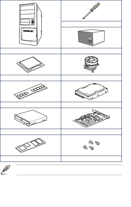
Installation tools and components
Phillips (cross) screwdriver
PC chassis |
Power supply unit |
Intel® LGA 1200 CPU |
Intel® LGA 1200 compatible CPU Fan |
DDR4 DIMM |
SATA hard disk drive |
SATA optical disc drive (optional) |
Graphics card (optional) |
M.2 SSD module (optional) |
1 Bag of screws |
The tools and components in the table above are not included in the motherboard package.
xiii

xiv

Product Introduction |
1 |
1.1Before you proceed
Take note of the following precautions before you install motherboard components or change any motherboard settings.
•Unplug the power cord from the wall socket before touching any component.
•Before handling components, use a grounded wrist strap or touch a safely grounded object or a metal object, such as the power supply case, to avoid damaging them due to static electricity.
•Hold components by the edges to avoid touching the ICs on them.
•Whenever you uninstall any component, place it on a grounded antistatic pad or in the bag that came with the component.
•Before you install or remove any component, ensure that the ATX power supply is switched off or the power cord is detached from the power supply. Failure to do so may cause severe damage to the motherboard, peripherals, or components.
<![endif]>Chapter 1
ROG STRIX B560-F GAMING Series |
1-1 |

<![endif]>1 Chapter
1.2Motherboard layout
HDMI _DP
BIOS_FLBK
19
 FLBK_LED
USB_2
U32G2X2_C1
U2_78U32G1_E34
LAN_U32G2_34
M.2(WIFI)
AUDIO |
<![if ! IE]> <![endif]>CON |
_TYPE-C |
<![if ! IE]> <![endif]>_ |
|
<![if ! IE]> <![endif]>LED1 |
6
3
6
22110
16
3
5 |
4 |
1 |
24.4cm(9.6in) |
4 |
|
|
20 |
2 |
12 |
|
|
|
|
|
|
|
|
|
|
|
|
|
|
|
|
|
<![if ! IE]> <![endif]>CPU DRAM VGA BOOT |
|
|
RGB_HEADER2 |
|
|
ATX_12V |
|
|
|
CPU_FAN |
|
|
|
|
<![if ! IE]> <![endif]>2 |
|
|
|
|
|
CPU_OPT |
|
|
|
|
<![if ! IE]> <![endif]>GEN2_ |
11 |
|
|
|
|
|
|
|
|
<![if ! IE]> <![endif]>ADD |
|
|
|
|
|
|
|
|
|
|
|
|
|
|
|
|
LGA1200 |
|
<![if ! IE]> <![endif]>(64bit,A1 288-pin module) |
<![if ! IE]> <![endif]>(64bit,A2* 288-pin module) |
<![if ! IE]> <![endif]>(64bit,B1 288-pin module) |
<![if ! IE]> <![endif]>(64bit,B2* 288-pin module) |
<![if ! IE]> <![endif]>ATXPWR |
5 |
|
|
|
|
|
|
|
|
|
||
|
|
|
|
|
<![if ! IE]> <![endif]>DIMM_ |
<![if ! IE]> <![endif]>DIMM_ |
<![if ! IE]> <![endif]>DIMM_ |
<![if ! IE]> <![endif]>DIMM_ |
|
8 |
|
|
|
|
|
<![if ! IE]> <![endif]>DDR4 |
<![if ! IE]> <![endif]>DDR4 |
<![if ! IE]> <![endif]>DDR4 |
<![if ! IE]> <![endif]>DDR4 |
|
|
| <![if ! IE]> <![endif]>1(SOCKET3) |
<![if ! IE]> <![endif]>FAN1CHA |
<![if ! IE]> <![endif]>PUMPAIO |
|
|
<![if ! IE]> <![endif]>E12U32G1 |
<![if ! IE]> <![endif]>30.5cm(12in) |
||||
|
|
|
|
|
||||||
|
|
|
|
|
|
|
|
|
<![if ! IE]> <![endif]>U325 |
|
|
|
|
|
|
|
|
|
|
|
9 |
|
|
|
|
|
PCIE SATA RAID ON CPU |
|
|
|
||
|
|
|
|
|
4.0 X4 |
X |
X |
|
|
|
|
2242 |
2260 |
2280 |
22110 |
M.2_1(SOCKET3) |
|
|
|
||
| <![if ! IE]> <![endif]>_ |
|
|
|
|
|
|
||||
| <![if ! IE]> <![endif]>M.2 |
|
|
|
|
|
|
|
|
|
|
|
PCIEX16_1 |
|
|
|
|
|
|
|
<![if ! IE]> <![endif]>1 |
|
|
|
|
|
|
|
|
|
<![if ! IE]> <![endif]>SATA6G |
|
|
|
|
|
|
|
|
|
|
|
|
|
|
|
|
|
<![if ! IE]> <![endif]>2(SOCKET3)M.2 |
<![if ! IE]> <![endif]>2 |
M.2_2(SOCKET3) |
TPM |
<![if ! IE]> <![endif]>SATA6G3 SATA6G |
|||
|
|
|
|
|
Intel® |
|
|
|
|
|
B560 |
2280 |
2260 |
|
2242 |
|
|
PCIE |
SATA |
IRST |
|
|
7 |
3.0 X4 |
V |
X |
|
|
<![if ! IE]> <![endif]>4 |
|
|
|
128Mb |
|
<![if ! IE]> <![endif]>SATA6G |
|
|
|
BIOS |
|
|
|
PCIEX16_2 |
|
|
||
|
|
|
|
|
|
<![if ! IE]> <![endif]>5 |
|
PCIE |
SATA |
IRST |
|
<![if ! IE]> <![endif]>3(SOCKET3)M.2 |
<![if ! IE]> <![endif]>SATA6G6SATA6G |
|
3.0 X4 |
X |
V |
|
|
|
M.2_1(SOCKET3)
PCIEX1_1 |
|
|
|
|
|
|
BATTERY |
22110 |
2280 |
2260 |
2242 |
|
|
|
|
AURA |
|
PCIEX1_2 |
|
|
|
|
6 |
COM_DEBUG |
AURA |
|
|
|
|
|
|
|
|
|
|
|
|
|
|
|
CHA_FAN2 CHA_FAN3 |
PANEL |
|
SPDIF_OUT |
RGB_HEADER1 |
|
|
|
|
|
AAFP |
TB_HEADER |
ADD GEN 2_1 |
USB_E12 |
USB_E34 |
CLRTC |
|
|
|
|
|
|||||
|
|
|
|
|
|
|
|
|
|
|
|
|
|
|
|
|
|
|
|
14 |
15 |
18 |
12 |
11 |
10 |
4 |
13 |
17 |
|
1-2 |
Chapter 1: Product Introduction |

Layout contents
1.CPU socket
2.DIMM slots
3.Expansion slots
4.Fan and Pump headers
5.Power connectors
6.M.2 slots
7.SATA 6GB/s ports
8.USB 3.2 Gen 1 connector
9.USB 3.2 Gen 1 header 10. USB 2.0 headers
11. AURA Addressable Gen2 headers
12. AURA RGB headers
13. Clear CMOS header
14. Front Panel Audio header
15. S/PDIF Out header
16. SPI TPM header
17. System Panel header
18. ThunderboltTM header
19. FlashBack™ LED
20. Q-LEDs
Page
1-4
1-5
1-7
1-8
1-9
1-10
1-11
1-12
1-12
1-13
1-14
1-15
1-16
1-17
1-17
1-18
1-19
1-20
1-21
1-21
<![endif]>Chapter 1
ROG STRIX B560-F GAMING Series |
1-3 |

<![endif]>1 Chapter
1.CPU socket
The motherboard comes with a LGA1200 socket designed for 11th Gen Intel® Core™ Processors & 10th Gen Intel® Core™, Pentium® Gold and Celeron® Processors.
LGA1200
•
•
•
•
•
•
Ensure that you install the correct CPU designed for LGA1200 socket only. DO NOT install a CPU designed for other sockets on the LGA1200 socket.
The CPU fits in only one correct orientation. DO NOT force the CPU into the socket to prevent bending the connectors on the socket and damaging the CPU.
Ensure that all power cables are unplugged before installing the CPU.
Upon purchase of the motherboard, ensure that the PnP cap is on the socket and the socket contacts are not bent. Contact your retailer immediately if the PnP cap is missing, or if you see any damage to the PnP cap/socket contacts/motherboard components. ASUS will shoulder the cost of repair only if the damage is shipment/ transit-related.
Keep the cap after installing the motherboard. ASUS will process Return Merchandise Authorization (RMA) requests only if the motherboard comes with the cap on the LGA1200 socket.
The product warranty does not cover damage to the socket contacts resulting from incorrect CPU installation/removal, or misplacement/loss/incorrect removal of the PnP cap.
1-4 |
Chapter 1: Product Introduction |

2.DIMM slots
The motherboard comes with Dual Inline Memory Modules (DIMM) slots designed for DDR4 (Double Data Rate 4) memory modules.
A DDR4 memory module is notched differently from a DDR, DDR2, or DDR3 module. DO NOT install a DDR, DDR2, or DDR3 memory module to the DDR4 slot.
|
|
|
|
|
|
|
|
|
|
|
|
|
|
|
|
|
|
|
|
|
|
|
|
|
|
|
|
|
|
|
|
|
<![if ! IE]> <![endif]>DIMM A1 DIMM A2* |
|
|
|
|
<![if ! IE]> <![endif]>DIMM B1 DIMM B2* |
|
|
|
|
|
|
|
|
|
|
|
|
|
|
|
|
|
|
|
|
|
|
|
|
|
|
|
|
|
|
|
|
|
|
|
|
|
||
|
|
|
|
|
|
|
|
|
|
|
|
|
|
|
|
|
|
|
|
|
|
|
|
|
|
|
|
|
|
|
|
|
|
|||||
|
|
|
|
|
|
|
|
|
|
|
|
|
|
|
|
|
|
|
|
|
|
|
|
|
|
|
|
|
|
|
|
|
||||||
|
|
|
|
|
|
|
|
|
|
|
|
|
|
|
|
|
|
|
|
|
|
|
|
|
|
|
|
|
|
|
|
|
||||||
|
|
|
|
|
|
|
|
|
|
|
|
|
|
|
|
|
|
|
|
|
|
|
|
|
|
|
|
|
|
|
|
|
|
|
|
|
|
|
|
|
|
|
|
|
|
|
|
|
|
|
|
|
|
|
|
|
|
|
|
|
|
|
|
|
|
|
|
|
|
|
|
|
|
|
|
|
|
|
|
|
|
|
|
|
|
|
|
|
|
|
|
|
|
|
|
|
|
|
|
|
|
|
|
|
|
|
|
|
|
|
|
|
|
|
|
|
|
|
|
|
|
|
|
|
|
|
|
|
|
|
|
|
|
|
|
|
|
|
|
|
|
|
|
|
|
|
|
|
|
|
|
|
|
|
|
|
|
|
|
|
|
|
|
|
|
|
|
|
|
|
|
|
|
|
|
|
|
|
|
|
|
|
|
|
|
|
|
|
|
|
|
|
|
|
|
|
|
|
|
|
|
|
|
|
|
|
|
|
|
|
|
|
|
|
|
|
|
|
|
|
|
|
|
|
|
|
|
|
|
|
|
|
|
|
|
|
|
|
|
|
|
|
|
|
|
|
|
|
|
|
|
|
|
|
|
|
|
|
|
|
|
|
|
|
|
|
|
|
|
|
|
|
|
|
|
|
|
|
|
|
|
|
|
|
|
|
|
|
|
|
|
|
|
|
|
|
|
|
|
|
|
|
|
|
|
|
|
|
|
|
|
|
|
|
|
|
|
|
|
|
|
|
|
|
|
|
|
|
|
|
|
|
|
|
|
|
|
|
|
|
|
|
|
|
|
|
|
|
|
|
|
|
|
|
|
|
|
|
|
|
|
|
|
|
|
|
|
|
|
|
|
|
|
|
|
|
|
|
|
|
|
|
|
|
|
|
|
|
|
|
|
|
|
|
|
|
|
|
|
|
|
|
|
|
|
|
|
|
|
|
|
|
|
|
|
|
|
|
|
|
|
|
|
|
|
|
|
|
|
|
|
|
|
|
|
|
|
|
|
|
|
|
|
|
|
|
|
|
|
|
|
|
|
|
|
|
|
|
|
|
|
|
|
|
|
|
|
|
|
|
|
|
|
|
|
|
|
|
|
|
|
|
|
|
|
|
|
|
|
|
|
|
|
|
|
|
|
|
|
|
|
|
|
|
|
|
|
|
|
|
|
|
|
|
|
|
|
|
|
|
|
|
|
|
|
|
|
|
|
|
|
|
|
|
|
|
|
|
|
|
|
|
|
|
|
|
|
|
|
|
|
|
|
|
|
|
|
|
|
|
|
|
|
|
|
|
|
|
|
|
|
|
|
|
|
|
|
|
|
|
|
|
|
|
|
|
|
|
|
|
|
|
|
|
|
|
|
|
|
|
|
|
|
|
|
|
|
|
|
|
|
|
|
|
|
|
|
|
|
|
|
|
|
|
|
|
|
|
|
|
|
|
|
|
|
|
|
|
|
|
|
|
|
|
|
|
|
|
|
|
|
|
|
|
|
|
|
|
|
|
|
|
|
|
|
|
|
|
|
|
|
|
|
|
|
|
|
|
|
|
|
|
|
|
|
|
|
|
|
|
|
|
|
|
|
|
|
|
|
|
|
|
|
|
|
|
|
|
|
|
|
|
|
|
|
|
|
|
|
|
|
|
|
|
|
|
|
|
|
|
|
|
|
|
|
|
|
|
|
|
|
|
|
|
|
|
|
|
|
|
|
|
|
|
|
|
|
|
|
|
|
|
|
|
|
|
|
|
|
|
|
|
|
|
|
|
|
|
|
|
|
|
|
|
|
|
|
|
|
|
|
|
|
|
|
|
|
|
|
|
|
|
|
|
|
|
|
|
|
|
|
|
|
|
|
|
|
|
<![endif]>Chapter 1
Recommended memory configurations
|
|
DIMM_A1 |
DIMM_A2* |
DIMM_A2* |
DIMM_A2* |
|
DIMM_B2* |
DIMM_B1 |
|
DIMM_B2* |
|
|
|
ROG STRIX B560-F GAMING Series |
1-5 |

<![endif]>1 Chapter
Memory configurations
You may install 4 GB, 8 GB, 16 GB, and 32 GB unbuffered and non ECC DDR4 DIMMs into the DIMM sockets.
You may install varying memory sizes in Channel A and Channel B. The system maps the total size of the lower-sized channel for the dual-channel configuration. Any excess memory from the higher-sized channel is then mapped for single-channel operation.
• The default memory operation frequency is dependent on its Serial Presence Detect (SPD), which is the standard way of accessing information from a memory module. Under the default state, some memory modules for overclocking may operate at a lower frequency than the vendor-marked value.
•For system stability, use a more efficient memory cooling system to support a full memory load or overclocking condition.
•Always install the DIMMS with the same CAS Latency. For an optimum compatibility, we recommend that you install memory modules of the same version or data code (D/C) from the same vendor. Check with the vendor to get the correct memory modules.
•Refer to www.asus.com for the Memory QVL (Qualified Vendors Lists), and memory frequency support depends on the CPU types.
1-6 |
Chapter 1: Product Introduction |
3.Expansion slots
Unplug the power cord before adding or removing expansion cards. Failure to do so may cause you physical injury and damage motherboard components.
<![if ! IE]><![endif]>Chapter 1
1 |
PCIEX16_1 |
2 |
PCIEX16_2 |
3 |
PCIEX1_1 |
4 |
PCIEX1_2 |
Please refer to the following tables for the recommended VGA configuration.
Recommended VGA configuration
Slot Description |
Single VGA |
|
1. |
PCIEX16_1 |
x16 |
2. |
PCIEX16_2 |
x4 |
The PCIEx16_2 slot shares bandwidth with M.2_2. When M.2_2 runs x4 mode,
PCIEX16_2 will be disabled.
ROG STRIX B560-F GAMING Series |
1-7 |

4.Fan and Pump headers
The Fan and Pump headers allow you to connect fans or pumps to cool the system.
<![endif]>1 Chapter
A |
B |
C D |
ACPU_FAN
BCPU_OPT
ECHA_FAN2
FCHA_FAN3
CCHA_FAN1
DAIO_PUMP
<![endif]>FAN PWM
<![if ! IE]><![endif]>FAN IN
<![if ! IE]><![endif]>FAN PWR
<![if ! IE]><![endif]>GND
FAN PWM 
 FAN IN
 FAN PWR

GND 

E F
•
•
DO NOT forget to connect the fan cables to the fan headers. Insufficient air flow inside the system may damage the motherboard components. These are not jumpers! Do not place jumper caps on the fan headers!
Ensure the cable is fully inserted into the header.
For water cooling kits, connect the pump connector to the AIO_PUMP header.
Header |
Max. Current |
Max. Power |
Default Speed |
Shared Control |
|
|
|
|
|
CPU_FAN |
1A |
12W |
Q-Fan Controlled |
A |
CPU_OPT |
1A |
12W |
Q-Fan Controlled |
A |
CHA_FAN1 |
1A |
12W |
Q-Fan Controlled |
- |
CHA_FAN2 |
1A |
12W |
Q-Fan Controlled |
- |
CHA_FAN3 |
1A |
12W |
Q-Fan Controlled |
- |
AIO_PUMP |
1A |
12W |
Full-Speed |
- |
1-8 |
Chapter 1: Product Introduction |
Loading...