


English
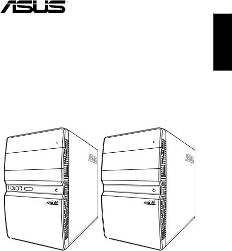
T4-Series
ASUS PC (Desktop Barebone)
Installation manual
Download the latest manual from the ASUS website: www.asus.com
English
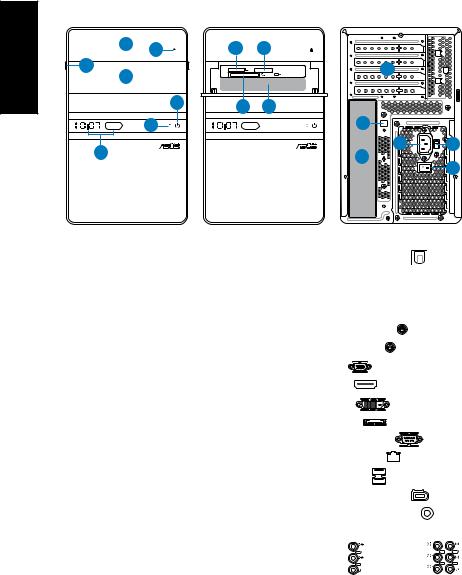
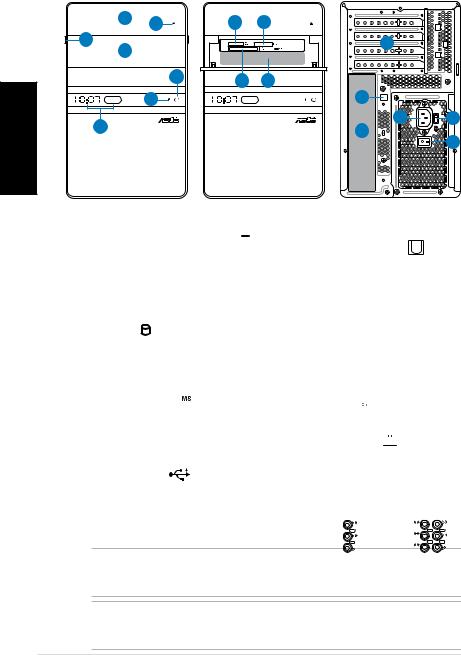
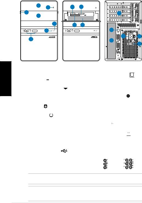
Front/Rear panel features
Front (Close) |
Front (Open) |
Rear |
||
1 |
2 |
8 |
9 |
|
3 |
4 |
|
12 |
|
|
|
|
|
7 |
10 |
11 |
|
6 |
|
13 |
5 |
14 |
15 |
17 |
16 |
|
|
|
1.Optical drive bay cover
2.Optical drive eject button ( )
)
3.Open the front panel cover (
 )
)
4.Front panel cover
5.Time and IR LED display (some models only)
6.HDD LED ( ) (lights up when the hard disk drive operates)
7.Power button ( ) (touchsensitive)
8.Memory Stick/
Memory Stick Pro card slot ( )
)
9.Secure Digital/ MultiMediaCard slot ( )
)
10.CompactFlash®/ Microdrive™ card slot (
 )
)
11.* • USB 2.0 ports ( )
)
•S/PDIF IN port (

 IN)
IN)
•4-pin IEEE 1394a port (
 )
)
•Headphone port ( )
)
•Microphone port ( )
)
12. Expansion slot metal brackets
13.* Optical S/PDIF Out port ( |
) |
|||||
14. |
Power connector |
|
|
|
||
15.** Voltage selector switch |
|
|||||
16. |
Power switch |
|
|
|
) |
|
17.* • PS/2 keyboard port ( |
|
|||||
|
• PS/2 mouse port ( |
) |
|
|
||
|
• VGA port ( |
|
) |
|
|
|
|
• HDMI port ( |
|
) |
) |
|
|
|
• DVI-D port ( |
|
|
|
|
|
|
• E-SATA port ( |
|
) |
) |
|
|
|
• Serial (COM1) port ( |
|
||||
|
• LAN (RJ-45) port ( |
) |
|
|||
|
• USB 2.0 ports ( |
) |
|
) |
||
|
• 6-pin IEEE 1394a port ( |
|||||
|
• Coaxial S/PDIF Out port ( |
) |
||||
|
•Audio ports configurations: |
|
||||
|
|
LINE |
|
|
|
C T R |
|
|
IN |
|
|
|
BASS |
|
• 6-channel |
|
• 8-channel |
REAR |
||
|
FRONT |
S P K |
||||
|
|
SIDE |
||||
|
MIC IN |
S P K |
||||
LINE
IN
FRONT
MIC IN
|
|
NOTE: *The front/rear panel ports and their locations may vary, depending on the |
|
|
model of your system. For detailed descriptions, refer to the system User Guide. |
|
|
|
|
|
|
|
|
NOTE: **The system’s power supply unit has a 115V / 230V voltage selector switch |
|
|
located beside the power connector. Use this switch to select the appropriate system |
|
|
input voltage according to the voltage supply in your area. |
|
|
|
|
|
Installation manual |
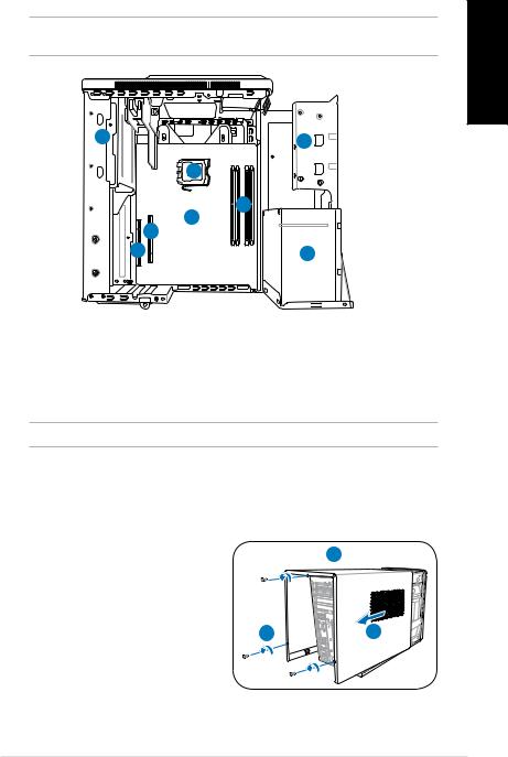
Internal components
NOTE: The illustration below shows the internal view of the system when you remove the cover and lift the power supply unit.
1 |
2 |
|
5 |
|
4 |
|
6 |
|
7 |
8 |
3 |
1. |
5.25-inch optical drive cage |
5. |
CPU socket |
2. |
3.5-inch hard disk drive cage |
6.* |
ASUS motherboard |
3. |
Power supply unit |
7. |
PCI Express x16 slot |
4. |
DIMM sockets |
8. |
PCI slot |
NOTE: *Refer to the system User Guide for motherboard details.
Removing the cover
1.Remove the three cover screws on the rear panel. Keep the screws for later use.
2.Pull the cover toward the rear panel.
3.Lift the cover, then set it aside.
 3
3
1 |
2 |
English
Installation manual

English
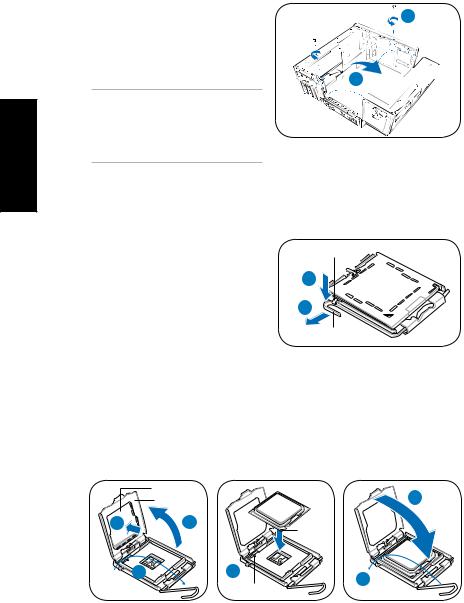
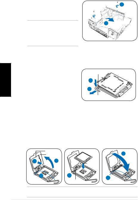
Lifting the power supply unit
1.Locate and remove the two screws.
2.Lift the PSU in the direction of the arrow to a 90º angle.
CAUTION: When removing the PSU, make sure to hold or support it firmly.
The unit might accidentally drop and damage the other system components.
1
2 


Installing a CPU
Installing an Intel® CPU in the LGA775 package
1.Locate the CPU socket on the motherboard.
2.Press the load lever with your thumb (2A), then move it to the left (2B) until it is released from the retention tab.
3.Lift the load lever in the direction of the arrow to a 135º angle.
Retention tab
2A
2B
Load lever
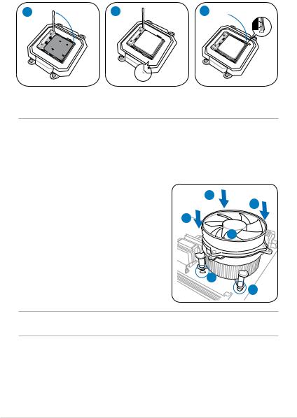
4.Lift the load plate with your thumb and forefinger to a 100º angle (4A), then push the PnP cap from the load plate window to remove (4B).
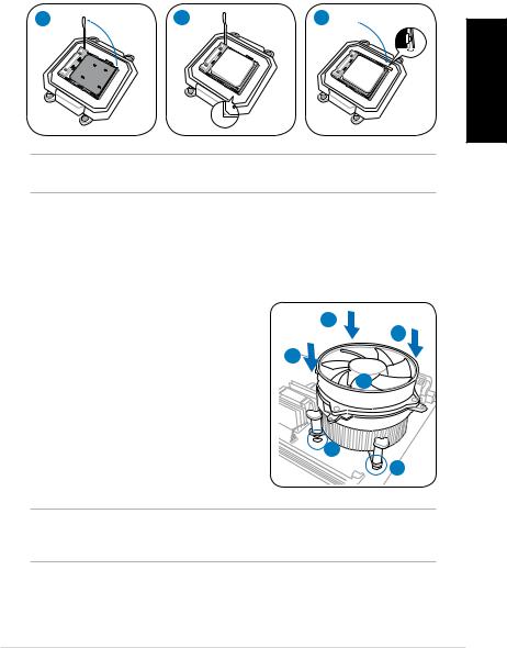
5.Position the CPU over the socket, making sure that the gold triangle is on the bottom left corner of the socket. Fit the socket alignment key into the CPU notch.
6.Close the load plate (6A), then push the load lever (6B) until it snaps into the retention tab.
|
PnP cap |
|
6A |
|
Load plate |
|
|
4B |
4A |
|
Gold |
|
|
|
triangle |
|
|
|
mark |
|
3 |
5 |
6B |
|
|
Alignment key |
|
|
|
|
CAUTION: Incorrect installation of the CPU into the socket may bend the pins and severely damage the CPU.
Installation manual
Installing an AMD CPU |
|
|
|
|
|
|
|
|
|
|
|
|
|
|
|
|
|
|
|
||
1. |
Locate the CPU socket, then lift the socket lever to a 90º angle. |
English |
||||||||
2. |
Install the CPU to the socket, making sure that the CPU corner with the gold |
|||||||||
|
triangle matches the socket corner with a small triangle. |
|||||||||
|
|
|||||||||
3. |
Push down the socket lever to secure the CPU. |
|
|
|
|
|
|
|||
|
1 |
2 |
|
|
3 |
|
|
|
|
|
|
|
|
|
|
|
|
|
|
|
|
|
|
|
|
|
|
|
|
|
|
|
|
|
|
|
|
|
|
|
|
|
|
|
|
|
|
|
|
|
|
|
|
|
|
|
|
|
|
|
|
|
|
|
|
|
|
|
|
|
|
|
|
|
|
|
CAUTION: Incorrect installation of the CPU into the socket may bend the pins and severely damage the CPU.
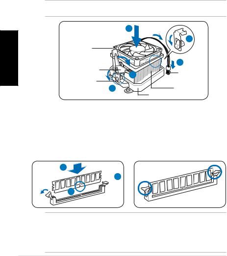
Installing the CPU fan and heatsink assembly
Installing an Intel® CPU heatsink and fan
1.Place the heatsink on top of the installed CPU, making sure that the four fasteners match the holes on the motherboard.
2.Push down two fasteners at a time in a diagonal sequence to secure the heatsink and fan assembly in place.
3.When the fan and heatsink assembly is in place, connect the CPU fan cable to the connector on the motherboard.
A
B
B
A 
1
1
CAUTION. Do not forget to connect the CPU fan connector! Hardware monitoring error can occur if you fail to plug this connector.
Installation manual

|
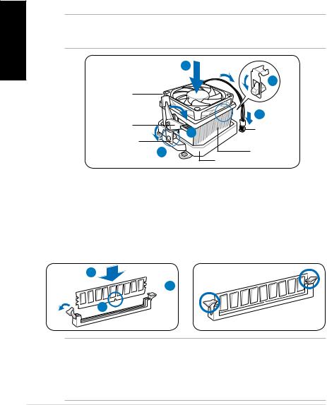
Installing an AMD CPU heatsink and fan |
|
|||
English |
1. |
Place the heatsink on top of the installed CPU. |
|
||
2. |
Attach one end of the retention bracket to the retention module base. |
||||
|
|||||
|
3. |
Attach the other end of the retention bracket (near the retention bracket lock) |
|||
|
|
to the retention module base until it clicks in place. |
|
||
|
4. |
Push down the retention bracket lock on the retention mechanism to secure |
|||
|
|
the fan and heatsink to the module retention module base. |
|||
|
5. |
Connect the CPU fan cable to the connector on the motherboard. |
|||
|
|
CAUTION. Do not forget to connect the CPU fan connector! Hardware monitoring error |
|||
|
|
can occur if you fail to plug this connector. |
|
||
|
|
|
1 |
|
|
|
|
|
|
2 |
|
|
|
CPU fan |
|
|
|
|
|
Retention |
|
5 |
|
|
|
|
CPU fan |
||
|
|
bracket lock |
4 |
||
|
|
Retention bracket |
connector |
||
|
|
3 |
CPU heatsink |
||
|
|
|
|||
|
|
|
Retention module base |
||
Installing a DIMM
1.Locate the DIMM sockets in the motherboard.
2.Unlock a DIMM socket by pressing the retaining clips outward.
3.Align a DIMM on the socket such that the notch on the DIMM matches the break on the socket.
4.Push the DIMM to the socket until the retaining clips snap inward.
4
 2
2
3
CAUTION:
•Unplug the power supply before adding or removing DIMMs. Failure to do so may cause damage to the motherboard and/or components.
•ADDR DIMM is keyed with a notch so that it fits in only one direction. Do not force a DIMM into a socket to avoid damaging the DIMM.
Installation manual

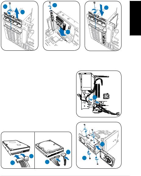
Installing an expansion card
1.Locate and remove one metal bracket lock screw.
2.Remove the metal bracket lock.
3.Align the card connector with the slot, then press firmly.
4.Secure the card with one screw.
5.Replace the metal braket lock, then secure it with one screw.
1 |
4 |
5 |
|
2 |
|||
|
|
||
|
|
3 |
Installing a hard disk drive
1.Connect the SATA/IDE power cable to the plug of the power supply unit.
2. |
Connect the SATA/IDE (2A) and power (2B) |
|
|
plugs to the connectors at the back of the |
|
|
SATA/IDE hard disk drives. |
|
3. |
Locate the HDD tray. |
1 |
4. |
Insert a hard disk drive (with the HDD PCB |
|
|
facing the top of the chassis) to the tray, |
|
|
then secure it with four screws. |
|
5. |
Connect the SATA/IDE signal cable to the |
|
|
SATA/IDE connector on the motherboard, and |
|
|
tighten all the cables with the plastic coils. |
|
|
SATA |
IDE |
|
|
4 |
|
2A |
2B |
|
4 |
|
|
|
|
|
2B |
2A |
English
Installation manual

English
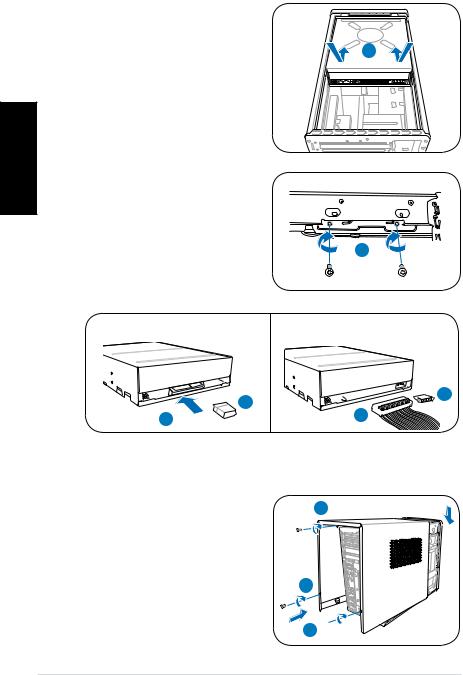
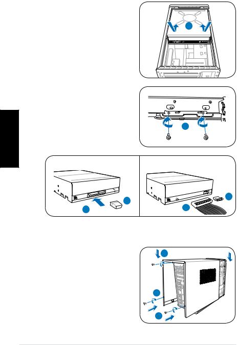
Installing an optical drive
1.Place the chassis upright.
2.Insert the SATA/IDE optical drive to the upper 5.25 in drive bay, then carefully push the drive until its screw holes align with the holes on the bay.
3.Secure the optical drive with four screws on both sides of the bay.
4.Connect the SATA/IDE (4A) and power plugs (4B) to the connectors at the back of the SATA/IDE drive.
2
3
SATA

 4A 4B
4A 4B 

Reinstalling the cover
1.Fit the cover tabs with the chassis rail and the front panel tabs (1A), then lower the rear edge of the cover as shown (1B).
2.Secure the cover with three screws.
IDE

 4B 4A
4B 4A 


 1B
1B
2
1A 
Installation manual
T4-Série
ASUS PC (Système barebone)
Manuel d’installation
Français
Téléchargez les derniers manuels depuis le site web d’ASUS: www.asus.com
Français
Caractéristiques de la façade/de l’arrière
Façade (Fermé) |
Façade (Ouvert) |
arrière |
||
1 |
2 |
8 |
9 |
|
3 |
4 |
|
12 |
|
|
|
|
|
|
|
7 |
10 |
11 |
|
|
6 |
|
13 |
|
|
5 |
|
14 |
15 |
|
|
17 |
16 |
|
|
|
|
|
1.Capot de la baie du lecteur optique
2.Bouton d’ejection du lecteur optique ( )
)
3.Ouverture de la façade avant (
 )
)
4.Façade
5.Ecranélectroluminescentd’affichage de l’heure et capteur Infrarouge (uniquement sur certains modèles)
6.LED HDD (
 ) (s’allume lorsque le disque dur est en cours d’opération)
7.Bouton d’alimentation ( ) (tactile)
8.Slot pour cartes Memory Stick/ Memory Stick Pro ( )
)
9.Slot pour cartes Secure Digital/ MultiMedia ( )
)
10.Slot pour cartes CompactFlash®/ Microdrive™ ( )
)
11.* • Ports USB 2.0 ( |
) |
•Port S/PDIF In (

 IN)
IN)
•Port IEEE 1394a 4 broches (
 )
)
•Port Casque ( )
)
•Port Microphone ( )
)
12.Supports métalliques des slots d’extension
13.* |
Port S/PDIF Out optique ( |
|
) |
|
|||
14. |
Connecteur d’alimentation |
||
15.** Interrupteur de sélection du voltage
16. Interrupteur d’alimentation
17.* • Port clavier PS/2 ( )
)
•Port souris PS/2 ( )
)
•Port VGA ( )
)
•Port HDMI ( )
)
•Port DVI-D ( )
)
•Port E-SATA (


 )
)
•Port Série (COM1) ( )
)
•Port LAN (RJ-45) (


 )
)
•Ports USB 2.0 ( )
)
•Port IEEE 1394a 6 broches ( )
)
•Port S/PDIF Out coaxial ( )
)
•Configurations des ports audio:
LINE |
C T R |
LINE |
IN |
BASS |
IN |
|
REAR |
FRONT |
FRONT |
S P K |
SIDE S P K NOTE: *Les ports/slots du panneau avant/arrière ainsi que leursMIC IN emplacements peuvent varier selon le modèle de votre système. Pour une description détaillée, reportez-vous au manuel de l’utilisateur de votre système.
MIC IN
NOTE: **L’alimentation du système est équipée d’un sélecteur de tension 115 V/230 V situé près du connecteur d’alimentation. Utilisez cet interrupteur pour choisir la bonne tension d’entrée en fonction des standards utilisés dans votre région.
|
Manuel d’installation |
Internal components
NOTE: L’illustration ci-dessous affiche une vue interne du système lorsque vous retirez le panneau latéral et soulevez le bloc d’alimentation.
1 |
2 |
|
5 |
|
4 |
|
6 |
|
7 |
8 |
3 |
1. |
Cage du lecteur optique 5.25” |
5. |
Socket du CPU |
2. |
Cage du lecteur de disque dur |
6.* |
Carte mère ASUS |
|
3.5’’ |
7. |
Slot PCI Express x16 |
8.Slot PCI
4.Sockets DIMM
NOTE: *Reportez-vous au manuel de l’utilisateur du système pour plus de détails sur la carte mère.3. Alimentation
Enlever le capot
1. Retirez les trois vis du panneau |
3 |
arrière. Conservez les vis pour un |
|
usage ultérieur. |
|
2.Faites glisser le panneau latéral vers l’arrière.
3. |
Soulevez le capot, puis basculez-le. |
1 |
2 |
Français
Manuel d’installation |
|
Français
Soulever le bloc d’alimentation
1.Localisez et retirez les deux vis du bloc d’alimentation.
2. Soulevez l’unité d’alimentation dans la direction de la flèche dans un angle de 90º.
ATTENTION: lorsque vous enlevez l’alimentation assurez-vous de bien la tenir car elle pourrait tomber et
endommager les autres composants du système.
1
2 


Installer un CPU
Installer un processeur Intel® au format LGA775
1.Localisez le socket du CPU sur la carte mère.
2.Pressez le levier avec votre pouce (2A) et glissez-le vers la gauche (2B) jusqu’à ce qu’il soit libéré du loquet de rétention.
3.Levez le levier dans la direction de la flèche à un angle de 135º.
Loquet de rétention
2A
2B
Levier
4.Levez la plaque avec votre pouce à un angle de 100°(4A), puis poussez le couvercle PnP de la plaque pour l’enlever (4B).
5.Placez le CPU au dessus du socket, en vous assurant que le triangle doré soit dans le coin inférieur gauche du socket. La clef d’alignement du socket doit correspondre avec l’encoche du CPU.
6.Refermez la plaque (6A), puis poussez le levier (6B) jusqu’à ce qu’il soit accroché par le loquet de rétention.
|
Plaque de |
|
|
|
protection |
|
6A |
|
plaque |
|
|
4B |
4A |
|
Marque |
|
|
|
triangulaire |
|
|
|
dorée |
|
3 |
5 |
6B |
|
|
Clef d’alignement |
|
|
|
|
|
ATTENTION: Une mauvaise installation du CPU sur le socket peut plier les broches et |
|
sérieusement endommager le CPU! |
|
|
|
|
|
Manuel d’installation |
Installer le AMD CPU
1.Repérez le socket du CPU, puis soulever le levier du socket de 90°.
2.Placez le CPU sur le socket, en vous assurant que le triangle doré sur le CPU est installé sur le triangle du socket.
3.Abaissez le levier du socket afin de sécuriser le CPU.
1 |
2 |
3 |
Français
ATTENTION: Une mauvaise installation du CPU sur le socket peut plier les broches et sérieusement endommager le CPU!
Installer l’ensemble dissipateur-ventilateur
Installer un ensemble dissipateur-ventilateur pour processeur Intel®
1.Placez le dissipateur sur le processeur, en vous assurant que les quatres systèmes de serrage correspondent aux trous de la carte mère.
2.Pressez sur deux systèmes de serrage à la fois en séquence diagonale pour fixer l’ensemble dissipateur-ventilateur.
3.Lorsque l’ensemble dissipateur-ventilateur est en place, connectez le câble du ventilateur CPU au connecteur de la carte mère étiqueté CPU_FAN.
A
B
B
A 
1
1
ATTENTION: N’oubliez pas de connecter le câble du ventilateur au connecteur de la carte mère! Des erreurs lors de la surveillance du matériel peuvent survenir si vous ne branchez pas ce connecteur.
Manuel d’installation |
|
Français
Installerunensembledissipateur-ventilateurpourprocesseurAMD
1.Placez l’ensemble ventilateur-dissipateur sur le CPU.
2.Fixez une extrémité de la patte de fixation au module de rétention.
3.Fixez l’autre extrémité de la patte de fixation (près du clip de fixation) au module de rétention jusqu’à ce qu’un clic se fasse entendre.
4.Abaissez les loquets de fixation du module de rétention afin de sécuriser l’ensemble dissipateur-ventilateur à la base du module.
5.Connectez le câble du ventilateur CPU au connecteur de la carte mère.
ATTENTION: N’oubliez pas de connecter le câble du ventilateur au connecteur de la carte mère! Des erreurs lors de la surveillance du matériel peuvent survenir si vous ne branchez pas ce connecteur.
1
|
|
2 |
|
Ventilateur CPU |
|
|
|
Clip de la patte |
|
5 |
|
|
Connecteur du |
||
de fixation |
4 |
||
ventilateur CPU |
|||
Patte de fixation |
3 |
Dissipateur CPU |
|
|
|||
|
|
Base du module de rétention |
Installer un module DIMM
1.Localisez les sockets DIMM de la carte mère.
2.Déverrouillez un socket DIMM en pressant sur les clips de rétention vers l’extérieur.
3.Alignez un module DIMM sur le socket de sorte que l’encoche sur la DIMM corresponde à l’ergot du socket.
4.Enfoncez le module DIMM dans le socket jusqu’à ce que les clips de rétention se referment.
4
 2
2
3
ATTENTION:
• Débranchez la source d’alimentation avant d’ajouter ou de retirer des modules DIMMs. Ne pas le faire peut endommager la carte mère et/ou les composants.
• Un module DDR DIMM est verrouillé par une encoche, de sorte qu’il ne peut entrer dans le socket que dans un seul sens. NE FORCEZ pas sur un module pour le faire entrer dans son socket pour ne pas l’endommager.
Manuel d’installation
Installer une carte d’extension
1.Repérez et retirez une des vis de blocage de l’attache métallique.
2.Retirez la sécurité de l’attache métallique.
3.Alignez le connecteur de la carte sur le slot, puis insérez-le fermement.
4.Fixez la carte à l’aide d’une vis.
5.Repositionnez la sécurité, puis fixez-la à l’aide d’une vis.
1 |
4 |
5 |
|
2 |
|||
|
|
||
|
|
3 |
Installer un disque dur
1.Connectez le câble d’alimentation SATA/ IDE à la prise du bloc d’alimentation.
2. |
Connectez les prises SATA/IDE (2A) et |
|
|
|
d’alimentation (2B) au connecteurs localisés |
|
|
|
à l’arrière des disques durs SATA/IDE. |
|
|
3. |
Repérez la baie pour disque dur. |
1 |
|
4. |
Insérez un disque dur (les circuits imprimés |
|
|
|
orientés vers le haut du châssis) dans la |
|
|
|
baie, puis fixez-le à l’aide de quatre vis. |
|
|
5. |
Reliez le câble SATA/IDE au connecteur |
|
|
|
SATA/IDE de la carte mère. Regroupez les |
|
|
|
câbles à l’aide des anneaux en plastique. |
|
|
|
SATA |
IDE |
|
|
|
|
4 |
|
|
2B |
|
|
|
2A |
4 |
|
2B |
2A |
|
|
|
||
Manuel d’installation
Français
Français
Installer un lecteur optique
1.Mettez le châssis en position verticale.
2.Insérez le SATA/IDE lecteur optique dans la baie 5.25” supérieure, puis faites le coulisser avec précaution, jusqu’à ce que ses pas de vis s’alignent avec ceux de la baie.
3.Fixez-le de part et d’autre de la baie à l’aide de quatre vis.
4.Connectez les câbles SATA/IDE (4A), et d’alimentation (4B) aux connecteurs situés à l’arrière du lecteur.
2
3
SATA

 4A 4B
4A 4B 

Réinstaller le panneau
1.Alignez les onglets du capot avec le rail du châssis et les onglets de la façade (1A), puis baissez le bord arrière comme indiqué (1B).
2.Fixez le capot avec trois vis.
IDE

 4B 4A
4B 4A 


 1B
1B
2
1A 
|
Manuel d’installation |

T4-Serie
ASUS PC (Desktop Barebone)
Installationshandbuch
Deutsch
Die neueste Version des Handbuchs finden Sie auf der ASUS-Website: www.asus.com
Frontseite/Rückseite
Vorderseite (geschlossen) |
Vorderseite (aufschieben) |
Rückseite |
||
1 |
2 |
8 |
9 |
|
3 |
4 |
|
12 |
|
|
|
|
|
7 |
10 |
11 |
|
6 |
|
13 |
5 |
14 |
15 |
17 |
16 |
|
|
|
Deutsch
1.Schubladenabdeckung des optischen Laufwerkes
2.Auswurftaste des optischen Laufwerkes ( )
)
3.Entfernen Sie die Vorderseitenabdeckung (
 )
)
4.Fronttafelabdeckung
5.Zeitund IR-LED-Anzeige (nur an einigen Modellen)
6.HDD-LED (
 ) (leuchtet auf, wenn die Festplatte arbeitet)
7.Stromschalter (  )
)
(berührungssensibel)
8.Memory Stick/ Memory Stick ProKartensteckplatz ( )
)
9.Secure Digital/ MultiMedia-Kartensteckplatz ( )
)
10.CompactFlash®/ Microdrive™- Kartensteckplatz ( )
)
11.* • USB 2.0-Anschlüsse ( |
) |
•S/PDIF-Eingang (

 IN)
IN)
•4-Pin-IEEE-1394a-Port (
 )
)
•Kopfhöreranschluss ( )
)
•Mikrofonanschluss ( )
)
12.Metallene Erweiterungssteckplatzklammern
13.* Optischer S/PDIF-Ausgang (  )
)
14.Stromanschluss
15.** Spannungsauswahlschalter
16.Stromschalter
17.* • PS/2-Tastaturanschluss ( )
•PS/2-Mausanschluss ( )
)
•VGA-Anschluss ( )
)
•HDMI-Anschluss ( )
)
•DVI-D-Ausgang ( )
)
•E-SATA-Port ( )
)
•Serieller (COM1) Anschluss ( )
)
•LAN (RJ-45)-Anschluss (


 )
)
•USB 2.0-Anschlüsse ( )
)
•6-Pin-IEEE-1394a-Port ( )
)
•Koaxialer S/PDIF-Ausgang ( )
)
•Audioanschlusseinstellungen:
|
LINE |
C T R |
LINE |
|
IN |
BASS |
IN |
• 6-Kanal |
MIC IN |
REAR |
MIC IN |
• 8-Kanal S P K |
|||
|
FRONT |
S P K |
FRONT |
|
|
SIDE |
|
HINWEIS:*Die Anschlüsse an Vorderund Rückseite und ihre Position können je nach
Modellvariieren.GenauereBeschreibungenfindenSieimBenutzerhandbuchdesSystems.
HINWEIS:**DasNetzteilistmiteinem115V/230V-SpannungsschalternebendemStromanschluss ausgestattet. Verwenden Sie diesen Schalter, um die passende Systemeingangsspannung entsprechend Ihrem Stromversorgungssystem in Ihrer Region auszuwählen.
Installationshandbuch

Interne Komponenten
HINWEIS: Die folgende Abbildung zeigt die interne Ansicht des Systems, wenn Sie die Abdeckung entfernen und das Netzteil anheben.
1 |
2 |
|
5 |
|
4 |
|
6 |
|
7 |
8 |
3 |
1. |
Halterung für optisches Laufwerk |
4. |
DIMM-Steckplätze |
|
|
5.25-Zoll |
5. |
Prozessorsockel |
|
2. |
Halterung für 3.5 Zoll |
6.* |
ASUS-Motherboard |
|
|
Festplattenlaufwerk |
7. |
PCI Express x16-Steckplatz |
|
3. |
Netzteil |
|||
8. |
PCI-Steckplatz |
|||
|
|
HINWEIS: *Details zum Motherboard finden Sie im Benutzerhandbuch des Systems.
Entfernen der Abdeckung
1. |
Entfernen Sie die drei |
|
3 |
|
Gehäuseschrauben an der |
|
|
|
|
|
|
|
Rücktafel. Die Schrauben für spätere |
|
|
|
Wiederverwendung gut aufheben. |
|
|
2. |
Ziehen Sie die Abdeckung nach |
|
|
|
hinten. |
1 |
2 |
3. Heben Sie die Abdeckung und legen sie zur Seite.
Deutsch
Installationshandbuch
Deutsch
Herausnehmen des Netzteils
1.Suchen und entfernen Sie die zwei Schrauben des Netzteils.
2. Heben Sie die PSU in Pfeilrichtung um 90º an.
ACHTUNG: Achten Sie beim Entfernen des Netzteils darauf, dass Sie das Netzteil gut festhalten. Das Netzteil kann aus Versehen herunterfallen
und die anderen Systemkomponenten beschädigen.
1
2 


Installieren einer CPU
Installieren einer Intel® CPU im LGA775-Paket
1.Lokalisieren Sie den Prozessorsockel auf dem Motherboard.
2.Drücken Sie den Arretierhebel mit Ihrem Daumen (2A) und schieben ihn nach links (2B), bis er von dem Halteriegel losgelassen wird.
Halteriegel
2A
2B
Arretierhebel
3.Ziehen Sie den Arretierhebel in die
Pfeilrichtung bis zu einem Winkel von 135º hoch.
4.Ziehe Sie den Deckrahmen mit Ihrem Daumen und Zeigefinger bis zu einem
Winkel von 100º hoch (4A) und drücken Sie dann die PnP-Abdeckung durch die Aussparung des Deckrahmens, um sie zu entfernen (4B).
5.Legen Sie die CPU auf den Sockel. Richten Sie dabei das goldene Dreieck auf die untere linke Ecke des Sockels aus. Die Sockelausrichtungsnase muss in die CPU-Kerbe einpassen.
6.Machen Sie den Deckrahmen (6A) zu. Drücken Sie anschließend den Arretierhebel (6B), bis er unter dem Halteriegel einrastet.
|
PnP- |
|
|
|
Abdeckung |
|
6A |
|
Deckrahmen |
|
|
4B |
4A |
|
Goldenes |
|
|
|
Dreieckzeichen |
|
3 |
5 |
6B |
|
|
Ausrichtungsnase |
|
|
|
|
ACHTUNG: Falscher Einbau des Prozessors kann die Anschlüsse verbiegen und den Prozessor ernsthaft beschädigen!
Installationshandbuch
Installieren einer AMD CPU
1.Suchen Sie den Prozessorsockel und heben den Hebel im Winkel von ca. 90º an.
2.Stecken Sie den Prozessor in den Sockel und vergewissern Sie sich, dass die Prozessorecke mit dem goldenen Dreieck mit dem kleinen Dreieck am Sockels übereinstimmt.
3.Drücken Sie den Sockelhebel zum Sichern des Prozessors herunter.
1 |
2 |
3 |
ACHTUNG: Falscher Einbau des Prozessors kann die Anschlüsse verbiegen und den Prozessor ernsthaft beschädigen!
Einbau des Prozessorlüfters und Kühlkörpers
Installieren eines Intel® CPU-Kühlkörpers und -Lüfters
1.Stellen Sie den Kühlkörper auf die installierte CPU. Stellen Sie dabei sicher, dass die vier Druckstifte auf die Löcher am Motherboard ausgerichtet wurden.
2.Drücken Sie jeweils zwei Druckstifte diagonal nach unten, um die Kühlkörper- Lüfter-Einheit zu befestigen.
3.Wenn die Kühlkörper/Lüfterbaugruppe platziert wurde, verbinden Sie das Prozessorlüfterkabel mit dem Anschluss auf dem Motherboard.
A
B
B
A 
1
1
ACHTUNG: Vergessen Sie nicht den Prozessorlüfter anzuschließen, die HarwareÜberwachung zeigt sonst einen Fehler an, wenn der Lüfter nicht angeschlossen ist.
Deutsch
Installationshandbuch
Deutsch
Installieren eines AMD CPU-Kühlkörpers und -Lüfters
1.Platzieren Sie den Kühlkörper auf dem installierten Prozessor.
2.Befestigen Sie ein Ende der Befestigungsklammmer an der Befestigungsmodulgrundplatte.
3.Befestigen Sie die andere Seite der Befestigungsklammer (nahe des Befestigungsklammerschlosses) auf der Grundplatte bis sie in der richtigen Position einrastet.
4.Drücken Sie die Befestigungsklammer auf den Befestigungsmechanismus, um den Prozessor, den Lüfter und den Kühlkörper an der Befestigungsgrundplatte zu sichern.
5.Verbinden Sie das Kabel des Lüfters mit dem Anschluss auf dem Motherboard.
ACHTUNG: Vergessen Sie nicht den Prozessorlüfter anzuschließen, die Harware-Überwachung zeigt sonst einen Fehler an, wenn der Lüfter nicht angeschlossen ist.
1
|
|
2 |
|
Prozessorlüfter |
|
|
|
Befestigungsklammer- |
|
5 |
|
|
Lüferanschluss- |
||
hebel |
4 |
||
kabel |
|||
Befestigungs- |
|
Prozessor- |
|
klammer |
3 |
||
|
kühlkörper |
||
|
|
Befestigungsmodul-grundplatte |
Installieren eines DIMMs
1.Suchen Sie die DIMM-Steckplätze auf dem Motherboard.
2.Entriegeln Sie einen DIMM-Steckplatz, indem Sie die Haltebügeln nach außen drücken.
3.Richten Sie ein DIMM auf den Steckplatz aus, wobei die Kerbe am DIMM auf die Unterbrechung des Steckplatzes ausgerichtet werden muss.
4.DrückenSiedasDIMM-ModulindenSockel,bisdieBefestigungsklammerneinrasten.
4
 2
2
3
ACHTUNG:
•Ziehen Sie den Netzstecker bevor Sie die DIMMs einoder ausbauen, sonst könnte das Motherboard und/oder andere Komponenten zerstört werden.
•Ein DDR DIMM hat eine Kerbe, so dass es nur in eine Richtung passt. Stecken Sie ein DIMM nicht mit übermäßiger Kraft in einen Steckplatz ein, um Schäden am DIMM zu vermeiden.
Installationshandbuch

Installieren einer Erweiterungskarte
1.Entfernen Sie die Schraube, mit der die Metallklammerhalterung befestigt ist.
2.Entfernen Sie die Metallklammerhalterung.
3.Stecken Sie die Karte in den Steckplatz ein und drücken dann fest nach unten, bis sie richtig sitzt.
4.Sichern Sie die Karte mit einer Schraube.
5.Setzen Sie die Metallklammerhalterung wieder ein und sichern Sie sie mit einer Schraube.
1 |
4 |
5 |
|
2 |
|||
|
|
||
|
|
3 |
Installieren einer Festplatte
1.Verbinden Sie das SATA/IDE-Stromkabel mit dem Netzteilstecker.
2. |
Verbinden Sie die SATA/IDE- (2A) und |
|
||
|
Netzstecker (2B) mit den Anschlüssen an |
|
||
|
der Rückseite der |
SATA/IDE-Laufwerke. |
|
|
3. |
Suchen Sie den HDD-Schacht. |
1 |
||
4. |
Schieben Sie die Festplatte (die HDD PCB zur |
|||
|
||||
|
Gehäuse-oberseite zeigend) in den Schacht |
|
||
|
und sichern Sie es mit den vier Schrauben. |
|
||
5. |
Verbinden Sie das SATA/IDE-Signalkabel |
|
||
|
mit dem SATA/IDE-Anschluss am |
|
||
|
Motherboard und befestigen Sie alle Kabel |
|
||
|
mit den Plastikschlaufen. |
|
||
|
SATA |
IDE |
|
|
|
|
|
4 |
|
|
2A |
2B |
|
|
|
|
4 |
||
|
2B |
2A |
||
|
|
|||
Installationshandbuch
Deutsch
Deutsch
Installieren eines optischen Laufwerks
1.Stellen Sie das Gehäuse aufrecht hin.
2.Stecken Sie das SATA/IDE optische Laufwerk in den oberen 5.25- Zoll-Schacht und schieben Sie vorsichtig, bis die Schraubenlöcher mit den Löchern am Schacht übereinstimmen.
3.Sichern Sie das Laufwerk mit jeweils 2 Schrauben auf jeder Seite des Schachtes.
4.Verbinden Sie die Stecker für SATA/ IDE (4A) und Stromversorgung (4B) mit den Anschlüssen an der Rückseite des Laufwerkes.
SATA

 4A 4B
4A 4B 

2
3
IDE

 4B 4A
4B 4A 


Wiederanbau der Gehäuseabdeckung
1. |
Passen Sie die Zähne der |
1B |
|
Abdeckung in die Nut am |
|
|
Gehäuse und die Haken an der |
|
|
Fronttafeleinheit ein (1A). Lassen |
|
|
Sie dann die hintere Kante der |
|
|
Abdeckung wie dargestellt runter |
|
|
(1B). |
2 |
2. |
Befestigen Sie die Abdeckung mit |
|
|
drei Schrauben. |
1A |
|
|
Installationshandbuch
 Loading...