


SC875

R
PCI-SC875
Ultra Fast & Wide SCSI Controller
USER’S MANUAL

ASUS PCI-SC875 User's Manual
II
USER'S NOTICE
Product Name: ASUS PCI-SC875
Manual Revision: 1.00
Release Date: November 1996
No part of this product, including the product and software may be reproduced,
transmitted, transcribed, stored in a retrieval system, or translated into any lan-
guage in any form by any means without the express written permission of ASUST eK
COMPUTER INC. (hereinafter referred to as ASUS) except documentation kept
by the purchaser for backup purposes.
ASUS provides this manual "as is" without warranty of any kind, either express or
implied, including but not limited to the implied warranties or conditions of mer-
chantability or fitness for a particular purpose. In no event shall ASUS be liable for
any loss or profits, loss of business, loss of use or data, interruption of business, or
for indirect, special, incidental, or consequential damages of any kind, even if ASUS
has been advised of the possibility of such damages arising from any defect or error
in this manual or product. ASUS may revise this manual from time to time without
notice.
Products mentioned in this manual are mentioned for identification purposes only.
Product names appearing in this manual may or may not be registered trademarks
or copyrights of their respective companies.
The product name and revision number are both printed on the board itself. Manual
revisions are released for each board design represented by the digit before and
after the period of the manual revision number . Manual updates are represented by
the third digit in the manual revision number . For updated BIOS, drivers, or prod-
uct release information you may visit ASUS' home page at: http://www .asus.com.tw/
© Copyright 1996 ASUSTeK COMPUTER INC. All rights reserved.

ASUS PCI-SC875 User's Manual III
ASUS CONTACT INFORMATION
ASUSTeK COMPUTER INC.
Marketing Info:
Address: 150 Li-Te Road, Peitou, Taipei, Taiwan, ROC
Telephone: 886-2-894-3447
Fax: 886-2-894-3449
Email: info@asus.com.tw
Technical Support:
Fax: 886-2-895-9254
BBS: 886-2-896-4667
Email: tsd@asus.com.tw
WWW: http://www.asus.com.tw/
Gopher: gopher.asus.com.tw
FTP: ftp.asus.com.tw/pub/ASUS
ASUS COMPUTER INTERNATIONAL
Marketing Info:
Address: 721 Charcot Avenue, San Jose, CA 95131, USA
Telephone: 1-408-474-0567
Fax: 1-408-474-0568
Email: info-usa@asus.com.tw
Technical Support:
BBS: 1-408-474-0555
Email: tsd-usa@asus.com.tw
ASUS COMPUTER GmbH
Marketing Info:
Address: Harkort Str. 25, 40880 Ratingen, BRD, Germany
Telephone: 49-2102-445011
Fax: 49-2102-442066
Email: info-ger@asus.com.tw
Technical Support:
BBS: 49-2102-448690
Email: tsd-ger@asus.com.tw

ASUS PCI-SC875 User's Manual
IV
CONTENTS
I. INTRODUCTION............................................................................ 1
How this manual is organized.......................................................... 1
Item Checklist .................................................................................. 1
Current Operating System Support ............................................ 1
II. FEATURES ..................................................................................... 2
Features of the ASUS SCSI Card .................................................... 2
Parts of the ASUS SCSI Card .......................................................... 2
III. INSTALLATION .......................................................................... 3
Inserting the Host Adapter in a PCI Slot.......................................... 3
Connecting SCSI Cables and Devices ............................................. 4
Choosing SCSI Cables ............................................................... 4
Maximum Cable Lengths ........................................................... 5
Connecting Internal SCSI Devices .................................................. 5
Connecting External SCSI Devices ........................................... 6
Connecting External 8-bit and 16-bit Devices ........................... 8
Terminating the SCSI Bus.......................................................... 8
SCSI IDs .......................................................................................... 9
SCSI ID Priority ......................................................................... 9
Setting SCSI IDs ........................................................................ 9
SCSI Bus Activity LED Connector............................................ 10
Completing Installation .............................................................. 10
IV. CONFIGURATION....................................................................... 11
Configuring Your Host Adapter ....................................................... 1 1
The Symbios Logic SCSI Configuration Utility.............................. 11
Main Menu....................................................................................... 12
Adapter Utilities Menu............................................................... 13
Adapter Setup Menu .................................................................. 13
Device Selections Menu............................................................. 13
Device Setup Menu .................................................................... 14
Quitting the SCSI Configuration Utility .................................... 14
V. DOS/WINDOWS DRIVERS........................................................ 15
Introduction...................................................................................... 15
When You Need to Load Drivers ............................................... 15
Automatic Installation of SDMS for DOS....................................... 15
ASPI8XX.SYS Driver Features ................................................. 16
Description ................................................................................. 16
Installing Your ASPI8XX.SYS Driver....................................... 17
Command Line Options ............................................................. 17
Troubleshooting ............................................................................... 21
SYMDISK.SYS Driver Features ..................................................... 22

ASUS PCI-SC875 User's Manual V
CONTENTS
Description ................................................................................. 22
Installing Your SYMDISK.SYS Driver ........................................... 23
Command Line Options ............................................................. 23
Troubleshooting ............................................................................... 26
SYMCD.SYS Driver Features ......................................................... 28
Description ................................................................................. 28
Installing Your SYMCD.SYS Driver............................................... 28
Command Line Options ............................................................. 29
Troubleshooting ......................................................................... 29
WIN8XX.386 Driver Features......................................................... 30
Description ................................................................................. 30
Installing Your WIN8XX.386 Driver .............................................. 30
Command Line Options ............................................................. 31
Troubleshooting ............................................................................... 34
Important Additional Information For Windows ............................. 35
Enabling 32-bit Disk and File Access in Windows .................... 35
Restrictions................................................................................. 35
Important Additional Information For DOS .................................... 35
Assignment of Drive Letters ...................................................... 35
Using the SDMS DOS Utilities ....................................................... 36
SCSI Low-level Format Utility .................................................. 36
Host Adapter Flash Utility ......................................................... 36
VI. WINDOWS 95 DRIVERS ............................................................ 37
SDMS DRIVER SYMC8XX.MPD V2.02.00 ................................. 37
Introduction for Windows 95 ........................................................... 37
Features ...................................................................................... 37
Description ................................................................................. 37
Installing Your SYMC8XX.MPD Driver ........................................ 38
Preparing a Symbios Driver Diskette......................................... 38
New System Installation ............................................................ 38
Existing System Installation....................................................... 39
Existing System Using ASPI8XX.SYS DOS ASPI Driver........ 40
Verifying Correct Driver Installation ......................................... 41
Command Line Options ............................................................. 41
Troubleshooting ......................................................................... 42
Important Additional Information.................................................... 43
Enabling/Disabling Ultra SCSI (Fast 20) Support ..................... 43
Multiple Symbios Logic Host Adapter Considerations ............. 44
Method 1............................................................................... 44
Method 2............................................................................... 44

ASUS PCI-SC875 User's Manual
VI
VII.WINDOWS NT DRIVERS .......................................................... 45
SDMS DRIVER SYMC8XX.SYS V2.03.00 .................................. 45
Introduction for Window NT 3.5x/4.x ............................................. 45
Features ...................................................................................... 46
Description ................................................................................. 46
Installing Your SYMC8XX.SYS Driver.......................................... 47
Preparing a Symbios Driver Diskette......................................... 47
New System Installation ............................................................ 47
Existing System Installation....................................................... 48
Windows NT 3.5x................................................................. 48
Windows NT 4.x................................................................... 49
Command Line Options ............................................................. 49
Troubleshooting ......................................................................... 50
Important Additional Information.................................................... 51
Enabling/Disabling Support Options ......................................... 51
VIII. NETWARE DRIVERS .............................................................. 52
Introduction...................................................................................... 52
Features ...................................................................................... 52
Description ................................................................................. 53
ASPI Support........................................................................ 53
Installing Your SDMS NetWare Drivers.......................................... 53
Existing Installation Of NetWare With SDMS Drivers ............. 53
For NetWare v3.12 New Installations ........................................ 54
For NetWare v4.xx New Installations ........................................ 55
For NetWare v4.1x SFT-III Installations.................................... 55
For NetWare v4.1x NWOS2 Installations.................................. 56
Command Line Options ............................................................. 56
The Power Management Utilities .................................................... 62
Installing the Power Management Utilities................................ 62
Manual Operation ................................................................. 65
Scheduled Operation ............................................................ 65
Unloading the PMSCHED.NLM Utility .............................. 65
Device Statistics ................................................................... 66
Important Additional Information.................................................... 66
For Information Pertaining to a Specific Driver ........................ 66
About Memory Allocation ......................................................... 66
Optimal Use of Command Line Options ................................... 67
Peripheral Device Dependent Optimizations ....................... 67
Flexibility ............................................................................. 67
Overall System Timing......................................................... 67
CONTENTS

ASUS PCI-SC875 User's Manual VII
DOS Access Dependencies ........................................................ 67
Supported DOS Configurations ................................................. 68
When Using An SDMS 3.XX BIOS .......................................... 68
Supported DOS Drivers........................................................ 68
DOS Drivers Not Supported................................................. 69
When Using An SDMS 4.XX BIOS .......................................... 69
Default Configuration........................................................... 69
NVRAM ............................................................................... 69
Supported DOS Drivers........................................................ 69
When Using No SDMS BIOS.................................................... 69
IX. SCO UNIX DRIVERS .................................................................. 70
SDMS SCO UNIX DRIVER V3.06.00 ........................................... 70
Introduction...................................................................................... 70
Features ...................................................................................... 71
Description ................................................................................. 71
Procedure 1 ........................................................................... 72
Existing System Installation ................................................. 72
Procedure 2 ........................................................................... 72
New System Installation....................................................... 72
The Symbios Logic............................................................... 72
CAM3 SCSI Configuration Tool.......................................... 72
Installing Your SCO UNIX Driver .................................................. 73
Existing System Installation....................................................... 73
New System Installation ............................................................ 79
Troubleshooting ......................................................................... 80
Important Additional Information.................................................... 82
How to Remove a SCSI Disk Drive From SCO UNIX ............. 82
X. UNIXWARE DRIVERS ................................................................. 83
LOGIC SDMS UNIXWARE DRIVER V3.02 ................................ 83
Introduction...................................................................................... 83
Features ...................................................................................... 84
Description ................................................................................. 84
Installing Your SDMS UnixWare Driver ......................................... 84
Installing the Driver During UnixWare Installation................... 84
Updating UnixWare 2.xx with the C8xx Driver ........................ 85
Loading the Package............................................................. 86
Configure for Statically Linked Driver ................................ 86
Configure for Dynamically Loadable Driver ....................... 86
Loading Loadable Module ................................................... 87
Rebuild the UnixWare Kernel .............................................. 87
Troubleshooting ......................................................................... 87
CONTENTS

ASUS PCI-SC875 User's Manual
VIII
FCC & DOC COMPLIANCE
Federal Communications Commission Statement
This device complies with FCC Rules Part 15. Operation is subject to the following
two conditions:
• This device may not cause harmful interference, and
• This device must accept any interference received, including interference that
may cause undesired operation.
This equipment has been tested and found to comply with the limits for a Class B
digital device, pursuant to Part 15 of the FCC Rules. These limits are designed to
provide reasonable protection against harmful interference in a residential installa-
tion. This equipment generates, uses and can radiate radio frequency energy and, if
not installed and used in accordance with manufacturer's instructions, may cause
harmful interference to radio communications. However, there is no guarantee that
interference will not occur in a particular installation. If this equipment does cause
harmful interference to radio or television reception, which can be determined by
turning the equipment off and on, the user is encouraged to try to correct the inter-
ference by one or more of the following measures:
• Re-orient or relocate the receiving antenna.
• Increase the separation between the equipment and receiver.
• Connect the equipment to an outlet on a circuit different from that to which
the receiver is connected.
• Consult the dealer or an experienced radio/TV technician for help.
WARNING: The use of shielded cables for connection of the monitor to the graphics
card is required to assure compliance with FCC regulations. Changes or modifica-
tions to this unit not expressly approved by the party responsible for compliance
could void the user's authority to operate this equipment.
Canadian Department of Communications Statement
This digital apparatus does not exceed the Class B limits for radio noise emissions
from digital apparatus set out in the Radio Interference Regulations of the Cana-
dian Department of Communications.

ASUS PCI-SC875 User’s Manual 1
I. INTRODUCTION
(Sections/Checklist)
I. INTRODUCTION
How this manual is organized
This manual is divided into the following sections:
I. Introduction: Manual information and checklist
II. Features: Information and specifications.
III. Installation: Instructions on setting up the ASUS PCI-SC875.
IV-IX. Driver Setup: SCSI driver and utility installation and usage.
Item Checklist
Please check that your package is complete. If you discover damaged or missing
items, please contact your retailer.
√ The ASUS PCI-SC875 Ultra-Fast & Ultra-Wide SCSI card
√ Support software on 4 diskettes:
1. DOS, BIOS, and Configuration Utilities
2. SDMS 4.0 PCI SCSI, Win95, WinNT, OS/2, Netware, Low Level Format
3. SCO Unix
4. Unixware 2.x
√ 50-Pin SCSI ribbon cable
√ This User’s Manual
Optional 68-Pin Wide-SCSI ribbon cable
Current Operating System Support
• DOS versions 5.0 and above
• Windows versions 3.0 and above
• Windows NT versions 3.1, 3.5x, 4.x
• Windows 95
• OS/2 versions 2.x and 3.x
• Netware 386 versions 3.x and 4.x
• SCO UNIX 3.2 version 4.0
• SCO Open Server Release 5
• Unixware 2.x
2 ASUS PCI-SC875 User’s Manual
II. FEATURES
(Features/Parts)
II. FEATURES
Features of the ASUS SCSI Card
The ASUS PCI-SC875 is carefully designed for the demanding PC user who wants
a high-end SCSI card for 8-bit and 16-bit SCSI devices. This SCSI card:
• 32-bit PCI: Has 32-bit PCI Local Bus interface
• Bus Master: Has PCI Bus Master Architecture
• Upgradeable BIOS: Has built-in programmable SCSI BIOS EPROM
• Dual Speeds: Supports Ultra Fast and Wide-SCSI Transfer Rates
• Multiple-SCSI support: Supports a combination of (7) 8-bit devices with 50-
Pin connector and (15) 16-bit devices with 68-Pin connector (not to exceed a
total of 15 SCSI devices per card)
• 3 Connectors: Has 1 external Wide-SCSI connector, 1 internal Wide-SCSI
connector, and 1 Internal Fast-SCSI connector (only 2 connectors usable at
one time)
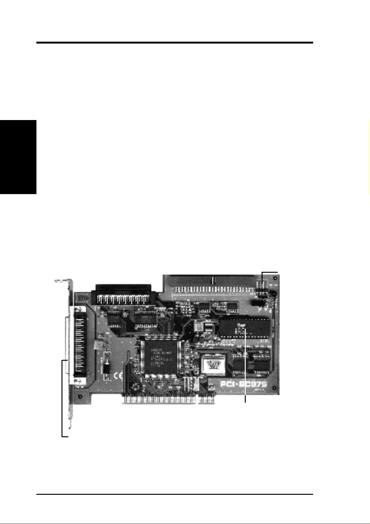
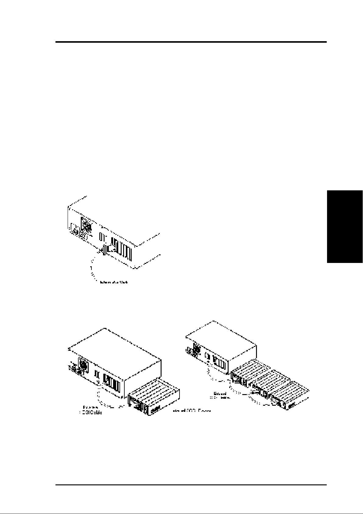
Parts of the ASUS SCSI Card
Internal 50-Pin Ultra Fast-SCSI
Internal 68-Pin Wide SCSI
Dual LED Leads
External 68-Pin Wide SCSI
Programmable BIOS EPROM

ASUS PCI-SC875 User’s Manual 3
This section explains how to physically install the SCSI card in your computer and
connect SCSI devices to it. You may need to run your computer’s Setup program as
part of the installation process. After the host adapter is physically installed, you
can change its configuration with the SDMS SCSI utility
You can install multiple SCSI cards in your computer if enough PCI bus slots are
available. Each SCSI card has two separate SCSI channels. If you install multiple
SCSI cards in your computer, you can enable the onboard BIOS on just one SCSI
card or on more than one of the SCSI cards.
Inserting the Host Adapter in a PCI Slot
1. Remove the cover from the computer case.
2. Carefully remove the host adapter from the antistatic bag. If you need to set the
adapter down, put it on top of the bag.
IMPORTANT: Keep the host adapter in its antistatic bag until you are ready
to install it. Before you pick up the adapter, ground yourself by touching an
unpainted surface on the computer chassis. Even a little static electricity can
destroy a host adapter component!
3. Find an unused 5volt PCI bus expansion slot that supports bus mastering. Make
sure this slot is unobstructed.
4. Remove the corresponding expansion slot cover from the computer chassis. The
slot cover is the metal strip in the back of the computer chassis that covers the
opening for the adapter’s external connector.
III. INSTALLATION
WARNING: Computer motheboards and components contain very delicate
Integrated Circuit (IC) chips. To protect the motherboard and other compo-
nents against damage from static electricity, you should follow some precau-
tions whenever you work on your computer.
1. Unplug your computer when working on the inside.
2. Hold components by the edges and try not to touch the IC chips, leads, or
circuitry.
3. Use a grounded wrist strap before handling computer components.
4. Place components on a grounded antistatic pad or on the bag that came with
the component whenever the components are separated from the system.
III. INSTALLATION
(Inserting Adapter)
4 ASUS PCI-SC875 User’s Manual
III. INSTALLATION
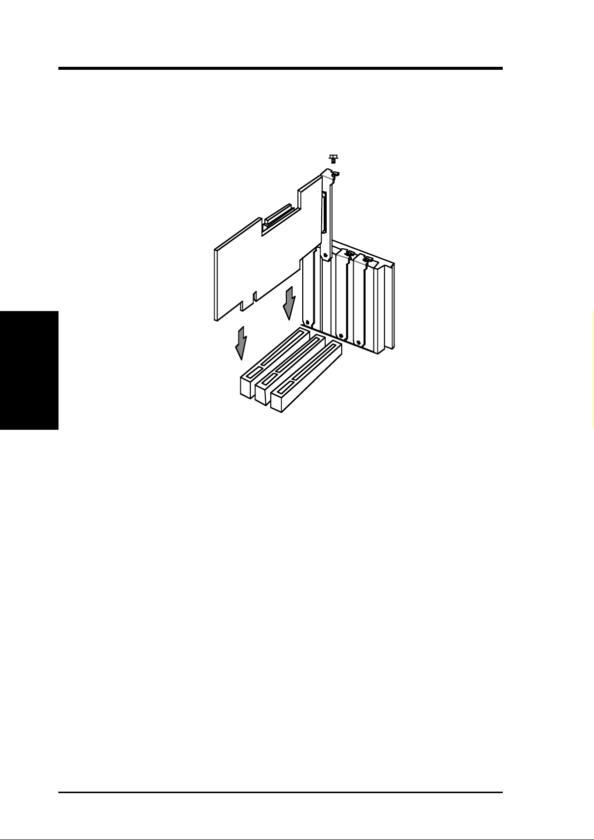
5. Position the host adapter directly over the PCI slot and insert the end of the
board in the card guide. Carefully press the bus connector on the bottom of the
host adapter down into the slot. Be sure the metal contacts on the bottom of the
host adapter are securely seated in the slot.
6. Attach the host adapter bracket to the computer chassis with the screw from the
slot cover that you removed in step 4.
NOTE: Do not replace the computer cover or reconnect the power yet!
Connecting SCSI Cables and Devices
Choosing SCSI Cables
Always use high-quality SCSI cables to connect the host adapter to devices on the
SCSI bus. Poor-quality cables can cause data corruption, parity errors, and other
problems. High-quality cabling is especially critical if you use UltraSCSI or Fast
SCSI data transfer rates.
The round cables used for external SCSI devices vary widely in quality and electri-
cal characteristics. Be sure external SCSI cables meet SCSI-2 standards (ask your
cable vendor). For UltraSCSI applications, SCSI cables must meet Fast-20 SCSI
standards. Here are some guidelines for external SCSI cables:
• SCSI-2: Use cables with a single-ended impedance range of 90 to 132ohms.
• UltraSCSI: Use cables with a single-ended impedance range of 90±10ohms. For
the req and ack signals the impedance should be 90±6ohms.
III. INSTALLATION
(SCSI Cables)
ASUS PCI-SC875 User’s Manual 5
Maximum Cable Lengths
T o assure reliable operation, the total length of the SCSI bus, including both internal
and external cabling, should not exceed 6meters (19.7 feet) for synchronous or asyn-
chronous data transfer rates, and 3meters (9.8 feet) for UltraSCSI data transfer rates.
WARNING: This SCSI controller support only single-ended SCSI devices.
Differential SCSI devices may be damaged if you connect them to the SCSI
bus. Read your SCSI device documentation if you are not sure whether a
device is single-ended or differential.
Connecting Internal SCSI Devices
Read the device documentation if you need to physically install a SCSI device in-
side your computer before attaching the cables. To connect internal SCSI devices to
an ASUS PCI-SC875 host adapter, you need the following:
• A 50pin internal SCSI ribbon cable.
• A 68pin internal SCSI ribbon cable.
There must be more connectors in the middle of the cable if you are attaching more
than one internal device. Make sure your cable has enough connectors. To connect
three or more internal SCSI devices to a SCSI bus, make a SCSI ribbon cable that
has enough connectors for all the SCSI devices.
You can connect both 8bit and 16-bit SCSI devices to an ASUS PCI-SC875 host
adapter. To attach 8bit internal devices to a wide SCSI bus, use a 68pin-to-50pin
converter.
You can buy this internal 68pin-to-50pin converter from any cable vendor.
Do not use this converter at the end of the cable; the converter does not provide
termination for the high data byte. To terminate a SCSI bus properly, you must put a
16-bit device at the end of the cable. If a converter with an 8-bit device is at the end
of the cable, the bus does not terminate properly.
T o attach a converter, first plug the converter into the SCSI device and then connect
the converter to the internal Wide SCSI ribbon cable.
III. INSTALLATION
III. INSTALLATION
(Internal SCSI)
6 ASUS PCI-SC875 User’s Manual
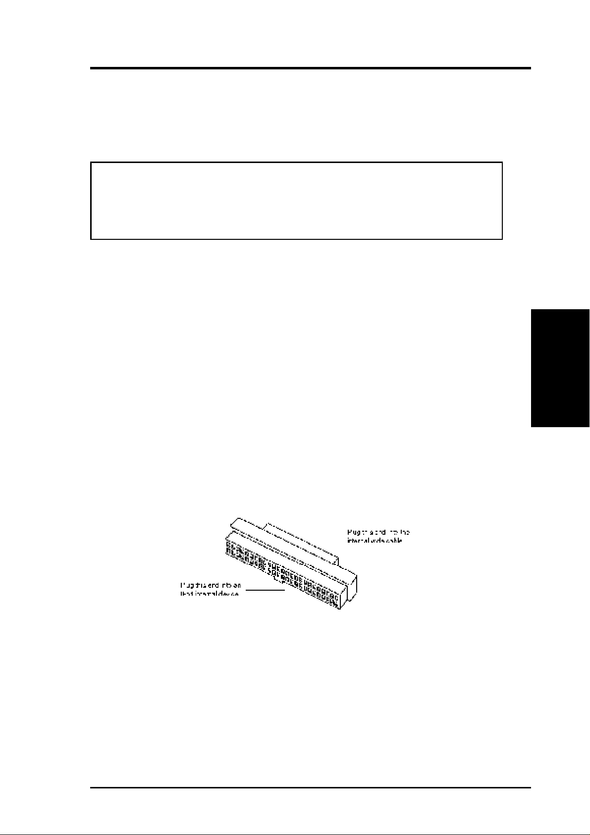
The following illustrations show the 50pin internal connector used with the ASUS
PCI-SC875. 68-pin Wide-SCSI connectors may also be used with Wide-SCSI de-
vices.
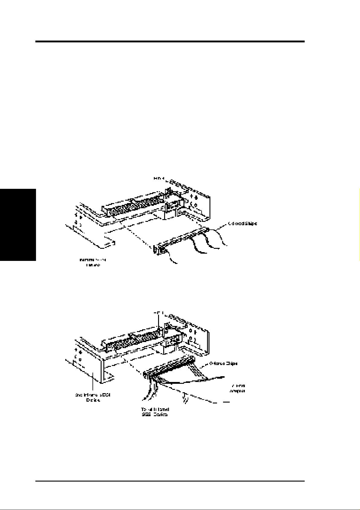
To connect internal SCSI devices, follow these steps:
1. Plug the SCSI connector at one end of the SCSI ribbon cable into one of the host
adapter’s internal SCSI connectors. Line up the colored stripe on the ribbon
cable with the number 1 printed below the connector on the host adapter . This is
called maintaining pin-1 orientation. Maintain pin-1 orientation throughout the
SCSI bus, or the devices will not work properly.
2. Plug the last connector on the ribbon cable into the SCSI connector on the inter-
nal SCSI device.
3. To connect a second internal SCSI device, plug the middle connector of the
SCSI ribbon cable into the SCSI connector on the second internal SCSI device.
4. To connect three or more internal SCSI devices to a SCSI bus, plug the remain-
ing middle SCSI connectors into the other internal devices.
III. INSTALLATION
III. INSTALLATION
(Internal SCSI)
ASUS PCI-SC875 User’s Manual 7
III. INSTALLATION
III. INSTALLATION
(External SCSI)
Connecting External SCSI Devices
You can daisy-chain up to seven SCSI devices to the internal 50-Pin connector. You
can daisy-chain up to fifteen SCSI devices to the internal or external 68-Pin connec-
tor. There is a limiation of a total of 15 SCSI devices per ASUS PCI-SC875 card.
Daisy-chaining means connecting multiple devices with multiple cables. For ex-
ample, a cable runs from the external SCSI connector to the first external device; a
second connector on the back of the external device allows another cable to connect
with the second device in the chain, and so forth.
External cable connectors can only be plugged in one way, so pin1 orientation is
automatic.
Follow these steps to connect external SCSI devices:
1. Attach one connector of the external SCSI cable to the external SCSI connector .
2. Attach the connector at the other end of the external cable to either one of the
SCSI connectors on the external SCSI device.
3. T o connect other external SCSI devices, daisy chain each device to the previous
device until all external SCSI devices have been connected.
8 ASUS PCI-SC875 User’s Manual
Connecting External 8-bit and 16-bit Devices
When daisy-chaining external 8-bit and 16-bit devices with standard SCSI-2 con-
nectors to the ASUS PCI-SC875, use an external SCSI-2 male 68-pin to SCSI-2
female 50-pin converter. Follow these steps:
1. Daisy-chain all 16-bit devices together with external SCSI-2 Wide cables.
2. Daisy-chain all 8-bit devices together with external SCSI-2 Narrow cables.
3. Connect the first device in the 16-bit device daisy chain to the host adapter with
an appropriate external Wide cable.
4. Plug the converter into the last device in the 16-bit device daisy chain.
5. Use an external narrow cable to connect the first 8-bit device in the 8-bit device
daisy-chain to the other end of the converter.
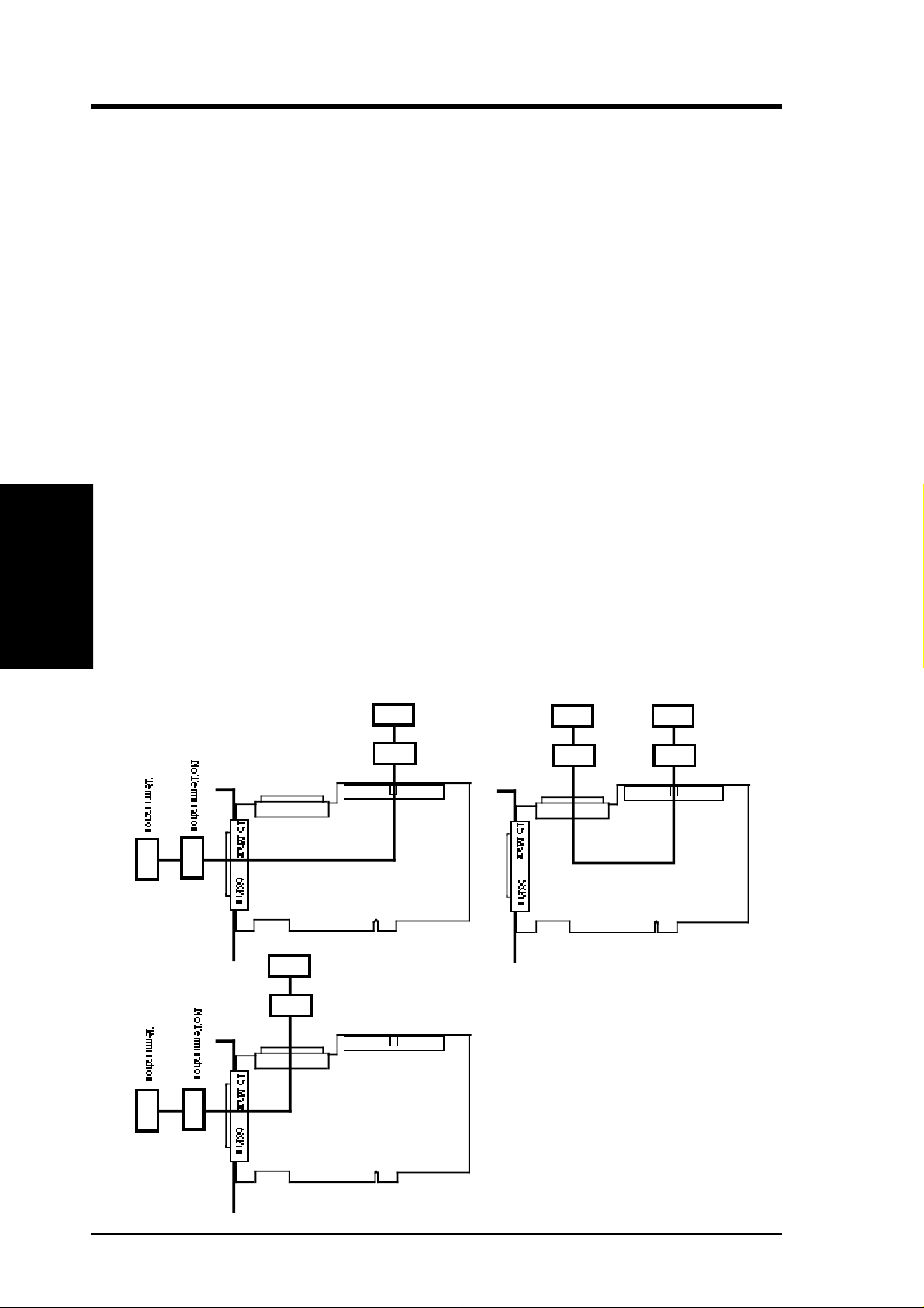
Terminating the SCSI Bus
The ASUS PCI-SC875 has auto termination so no jumpers are necessary . Terminat-
ing the devices on the ends of the SCSI Bus is necessary for SCSI devices to work
properly. Termination of the devices between the ends must be Disabled. Connect
SCSI devices to two of the three connectors in a linear “chain” for auto termination
of the ASUS PCI-SC875 to be effective. Other formations will cause your SCSI
devices to not mount properly . Y ou must use the end of the ribbon cable when using
the internal connector(s) to keep a linear path. The following shows three possible
chains for this SCSI card:
50Pin
68Pin
15 SCSI Devices Total per Card
7 Max
15 Max
Termination
No Termination
50Pin
68Pin
15 SCSI Devices Total per Card
7 Max
15 Max
Termination
No Termination
Termination
No Termination
50Pin
68Pin
15 SCSI Devices Total per Card
7 Max
15 Max
Termination
No Termination
III. INSTALLATION
III. INSTALLATION
(Termination)

ASUS PCI-SC875 User’s Manual 9
III. INSTALLATION
(SCSI IDs)
III. INSTALLATION
SCSI IDs
Each device on the SCSI bus, including the host adapter, must have a unique SCSI
ID. The SCSI ID serves two purposes:
• It uniquely defines each SCSI device on the bus.
• It determines which device controls the bus when two or more devices try to use
it at the same time.
SCSI IDs on one channel do not interfere with the IDs on another channel. This
applies to two SCSI host adapters that implement different buses as well as dual
channels on a single host adapter.
SCSI ID Priority
On an 8bit SCSI bus, SCSI ID 7 has the highest priority, and SCSI ID 0 has the
lowest priority. From highest to lowest, the complete order is: 7, 6, 5, 4, 3, 2, 1, 0.
On a 16bit SCSI bus, the priority scheme goes from SCSI ID 7 (the highest priority)
to SCSI ID 0, and then from SCSI ID 15 to SCSI ID 8, so that SCSI ID 8 is the very
lowest priority . From highest to lowest, the complete order is: 7, 6, 5, 4, 3, 2, 1, 0, 15,
14, 13, 12, 11, 10, 9, 8.
Setting SCSI IDs
Setting SCSI IDs is a two-step process:
1. Determine the SCSI ID of each device on the SCSI bus.
The default SCSI ID for the host adapter is 7, the highest priority on the bus.
Y ou can change the SCSI ID of the host adapter using the Symbios SCSI Firmare
Setup (see section IV), if necessary , but it is recommended that you leave the ID
on 7. T o determine the SCSI IDs of SCSI devices, read the devices’ documenta-
tion and examine their switch settings or jumper settings.
2. Set the SCSI IDs so that no IDs are duplicated on the same SCSI channel.
10 ASUS PCI-SC875 User’s Manual
III. INSTALLATION
III. INSTALLATION
(Activity LED)
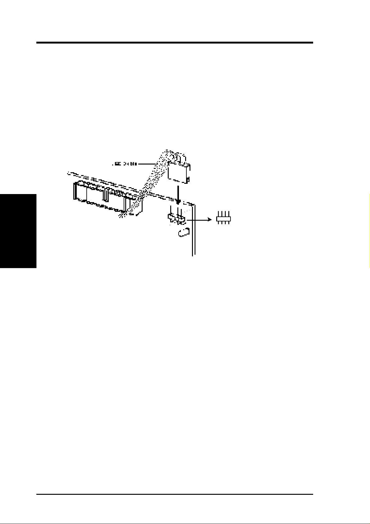
SCSI Bus Activity LED Connector
Most computers have an LED disk activity light on the front panel. If you discon-
nect the cable from the motherboard and attach it to the LED connector on the host
adapter, the LED will light whenever there is activity on either SCSI channel.
Follow these steps to connect the LED cable to the host adapter:
1. Refer to your computer’s documentation to locate the LED cable and unplug it
from the connector on the motherboard.
2. Connect the LED cable to the SCSI activity LED connector on the host adapter .
+ - - +
1
1
Use a four pin connector if available or connect one LED to pins 1-2, and another to
pins 3-4 if needed. The two LED leads 1-2 & 3-4 are the same.
Completing Installation
Before you reassemble your computer, be sure that
• The devices on each SCSI channel are properly terminated
• Each SCSI device on each SCSI channel has a unique SCSI ID
• The host adapter is firmly seated and secured in a 5volt bus master PCI bus slot
• Internal SCSI devices have power plugs attached
• Internal SCSI devices are firmly connected to the host adapter and pin1 orienta-
tion is correct
• External SCSI devices are firmly connected to the host adapter
Complete these steps to finish the installation process:
1. Replace and secure the cover of the computer case.
2. Reconnect the power cords to all external SCSI devices and the computer.
3. Turn ON the power to all devices.
4. Boot the computer.

ASUS PCI-SC875 User’s Manual 11
IV. CONFIGURATION
IV. CONFIGURATOIN
(Symbios Utility)
Configuring Your Host Adapter
In most cases you should not need to change the default configuration of your host
adapter. You may decide to alter these default values if there is a conflict between
device settings, or if you need to optimize system performance.
To perform the configuration described in this chapter you must have SDMS BIOS
version 4.xx.xx or higher, and it must include the Symbios Logic SCSI Configura-
tion utility. You can see the version number of your SDMS BIOS in a banner dis-
played on you computer monitor during bootup. If the utility is available, a message
appears on your computer monitor (for about 5 seconds) during bootup that looks
like this:
Press Ctrl-C to start Configuration Utility
The Symbios Logic SCSI Configuration Utility
The menu driven Symbios Logic SCSI Configuration Utility allows you to view and
change the default configuration settings for your host adapter.
NOTE: This utility is a powerful tool. If, while using it, you somehow disable
all your controllers or cannot enter the configuration utility, pressing “Ctrl-A”
after memory count during reboot allows you to recover and reconfigure.
The following tables list the configuration settings you can change. The global
settings affect your host adapter and all SCSI devices which are connected to it. The
device settings affect only individual SCSI devices.
Settings for the Host Adapter & All Devices Default Settings
SCAM Support On
Parity Checking Enabled
Host Adapter SCSI ID 7
Scan Order Low to High (0-Max)
Settings for Individual SCSI Devices Default Settings
Synchronous Transfer Rate (MS/Sec) 20
Data Width 16
Disconnect On
Read Write I/O Timeout (secs) 10
Scan for Devices at Boot Time Yes
Scan for SCSI LUNs Yes
Queue Tags Enabled

12 ASUS PCI-SC875 User’s Manual
IV. CONFIGURATION
Main Menu
When you start the Symbios Logic Configuration Utility, your computer monitor
displays the Main menu. This menu is your entry to the utility.
The Main menu displays a list of up to four Symbios Logic PCI to SCSI host adapt-
ers in you system, and information about each of them.
By using the arrow keys, an adapter is selected to view and/or change current set-
tings for the adapter, and the SCSI devices attached to it. An adapter is selectable
only if the current status is “On”. Changes are possible only if NvRAM (non-vola-
tile memory on your adapter) is present.
Following the list of host adapters on the Main menu display, you see the options
described below . If these settings are altered, the system reboots upon exit from the
configuration utility by the Quit option.
Adapter Boot Order - allows you to set the order in which host adapters boot when
you have more than one Symbios Logic host adapter in your system. When this
option is selected, the Boot Order menu is shown.
T o change an apapter’s boot order , select it and press Enter. You are then prompted
to enter the new boot sequence number. When the adapters are ordered properly,
press the Escape key to exit this menu.
Change Adapter Status - allows you to activate or deactivate a host adapter and all
SCSI devices attached to it. The change takes place after a reboot, which is auto-
matic upon exit from the utility when this option is used to make a change. When
this option is selected the Change Status menu is displayed.
To change an adapter’s status, select it and press Enter. Then press the escape key
to exit this menu.
Display Mode - determines how much information about your host adapter(s) and
SCSI devices is displayed on your computer monitor during boot. For more com-
plete information, choose the verbose setting. For a faster boot, choose the terse
setting.
Mono/Color - allows you to choose between a black and white or color display for
the SCSI Configuration utility. You might need to choose the mono setting to get a
more readable screen on a black and white monitor.
Help - brings up a help screen with information about the Main menu.
Quit - gets you out of the SCSI Configuration utility.
IV. CONFIGURATION
(Main Menu)

ASUS PCI-SC875 User’s Manual 13
IV. CONFIGURATION
Adapter Utilities Menu
When you select a host adapter from the Main menu, you will see new screen. Choose
“A-Adapter Setup” to view and change the selected adapter settings. Choose
“D-Device Selections” to view and change settings for the devices attached to the
selected adapter.
You come back to this menu after making changes to the configuration of any host
adapter or connected SCSI device. Before you exit this menu, you are prompted to
save or cancel the changes.
Adapter Setup Menu
When you select “Adapter Setup” your computer monitor displays the Setup menu.
The settings in this menu are global settings that affect the selected host adapter and
all SCSI devices attached to it.
SCAM Support - The Symbios Logic BIOS version 4.x and above supports the
SCSI Plug and Play protocol called SCAM (SCSI Configured AutoMatically). You
may choose to turn this off.
Parity - Symbios Logic PCI to SCSI host adapters always generate parity , but some
SCSI devices do not. Therefore, you are offered the option of disabling parity check-
ing.
NOTE: When disabling parity checking, you may have to disable disconnects
for certain devices as pairty checking for the reselection phase is not disabled.
If a device does not generate parity , and it disconnects, the I/O never completes
because the reselection never completes.
Host SCSI ID - In general, it is suggested that you not change your host apapter ID
from the default value of 7, as this gives it the highest priority on the SCSI bus.
However, if you have two adapters sharing the same SCSI devices, you should give
one of them a currently unassigned ID to avoid duplication of SCSI IDs.
Scan Order - This option allows you to tell the host adapter BIOS and you device
drivers to scan the SCSI bus from low to high (0 to max) SCSI ID, or from high to
low (max to 0) SCSI ID. If you have more than one device on the SCSI bus, chang-
ing the scan order changes the order in which drive letters are assigned by the sys-
tem.
Device Selections Menu
When you select “Device Setup”, your computer monitor displays a new menu.
This menu provides information about individual SCSI devices attached to the se-
lected host adapter, and the adapter itself. To make changes to these settings, select
a device from the display and press Enter to bring up the individual Device Setup
menu.
IV. CONFIGURATION
(Utilities/Setup/Device)

14 ASUS PCI-SC875 User’s Manual
IV. CONFIGURATION
Device Setup Menu
When you select a specific device from the Device Selections menu, your computer
monitor displays a new menu. The settings in this menu affect individual SCSI
devices attached to the selected host adapter . Changes made from this menu do not
cause the sytem to reboot upon exit from the SCSI Configuration utility.
Sync Rate (Mega Bytes/sec) - The value set with this option defines the maximum
transfer rate the host adapter attempts to negotiate. The host adapter and a SCSI
device must agree to a rate they can both handle.
Width (bits) - The value set with this option defines the maximum data width the
host adapter attempts to negotiate. The host adapter and a SCSI device must agree
to a width they can both handle. Only host adapters that can do 16 bit data transfers
have this option enabled.
Disconnect - SCSI devices have the ability to disconnect from the bus during an I/O
transfer. This option tells the host adapter whether or not to allow a device to dis-
connect. Some devices run faster with disconnects enabled (mostly newer devices),
while some run faster with disconnects disabled (mostly older devices).
Read Write I/O Timeout (secs) - This option sets the time the host adapter waits
for a read, write, verify , or seek command to complete before trying the I/O transfer
again. Since this provides a safeguard allowing the sytem to recover if an I/O opera-
tion fails, it is recommended that you always set the time-out to a value greater than
zero (no time-out).
Scan for Device at Boot Time - When there is a device you do not wish to make
available to the system, set this option to “No” for that device. Also, on a wide bus
(16 devices) with only a few devices attached, you can speed up boot time by chang-
ing this setting to “No” for all unused SCSI IDs.
Scan for SCSI LUNs - (Logical Unit Number-0 to 7) You can set this option to
“No” if you have problems with a device that responds to all LUNs whether they are
occupied or not.
Queue Tags - If your device driver can issue queue tags, this option allows you to
enable or disable the issuing of queue tags during I/O requests.
Quitting the SCSI Configuration Utility
Since some changes only take affect after your system reboots, it is important that
you quit this Configuration utility properly. You should return to the Main Menu
and exit by the Quit option. If you reboot the system without properly quitting the
utility, some changes will not take be saved.
IV. CONFIGURATION
(Device Setup/Quiting)

ASUS PCI-SC875 User’s Manual 15
V. DOS/WINDOWS DRIVERS
V. DOS/WINDOWS
(Introduction)
Introduction
In SDMS 4.0, the SCSI BIOS for the Symbios Logic family of PCI SCSI chips is
capable of mapping SCSI hard disk drives behind any non-SCSI hard disk drives
(IDE, ESDI, etc.) within the same system. A driverless solution will allow connec-
tion of up to 24 hard drives (SCSI and non-SCSI) under DOS 5.0 and above.
Full Virtual DMA Services (VDS), including features such as scatter-gather, are
also supported by the SCSI BIOS. Therefore, to gain maximum performance, you
should disable any double buffer option provided by disk caching software (such as
Microsoft’s SMARTDRV.EXE) for all drives handled through SDMS.
When You Need to Load Drivers
Connecting peripherals other than hard disk drives requires loading the appropriate
driver . Some of the drivers work together, and some are capable of direct communi-
cation with a Symbios Logic PCI/SCSI controller.
ASPI8XX.SYS is an ASPI (Advanced SCSI Programming Interface) manager which
provides standard ASPI compatibility between your SCSI host adapter hardware
and ASPI compatible applications. SYMDISK.SYS is a device driver for SCSI disk
drives, and works through the ASPI manager. SYMCD.SYS is a device driver for
CDROM drives, and works through the ASPI manager.
The following sections list these drivers, their features, and their loading require-
ments.
Automatic Installation of SDMS for DOS
Using the DOS Installation Utility
The Symbios Logic SDMS DOS installation utility provides a quick and easy method
for performing either an automatic or custom installation of the SCSI device drivers
in a DOS/Windows environment.
It works with any system using an SDMS supported Symbios Logic SCSI chip. The
installation utility identifies the system, scans the SCSI bus, and properly installs
the needed SCSI device drivers.
The SDMS Drivers diskette containing the DOS device drivers also holds the DOS
installation utility . To use the utility, insert disk 1 into your floppy drive while in the
DOS environment, and change to the A:\DOS directory, then type: INSTALL.
Follow the directions presented on the screens.
When performing a custom installation, an understanding of the information pre-
sented in the following sections for manual installation may prove useful.

16 ASUS PCI-SC875 User’s Manual
V. DOS/WINDOWS DRIVERS
V. DOS/WINDOWS
(Features)
ASPI8XX.SYS Driver Features
• Supports Advanced SCSI Programming Interface (ASPI) applications
• Supports single-threaded I/O
• Supports up to four host adapters
• Releases initialization code for smaller runtime size
• Performs synchronous negotiation (including Fast-20)
• Performs Wide SCSI negotiation
• Full VDS (Virtual DMA Services) support, including scatter-gather
• Allows Disconnect/Reselect
• Supports adapter exclusion
• Allows shared interrupts
Description
ASPI8XX.SYS is an ASPI manager which provides an interface to popular ASPI
applications. It is required when you want to use SYMDISK.SYS or SYMCD.SYS,
or whenever you want to run an ASPI application.
ASPI8XX.SYS replaces an SDMS BIOS (if present), and fully supports all devices
supported by the BIOS. If an SDMS BIOS is not present, only an ASPI interface is
provided.

ASUS PCI-SC875 User’s Manual 17
V. DOS/WINDOWS DRIVERS
V. DOS/WINDOWS
(Installation)
Installing Your ASPI8XX.SYS Driver
1. Use the COPY command to copy the ASPI8XX.SYS driver from the SDMS
SCSI Drivers disk to your boot disk.
2. Add this line to your system’s CONFIG.SYS file:
DEVICE=C:[path]ASPI8XX.SYS
This line must appear before any line loading other ASPI drivers (like SYMCD.SYS,
SYMDISK.SYS, or any other ASPI compliant driver/application).
Command Line Options
The ASPI8XX.SYS driver has several configurable features which are set via switches
on the command line in your CONFIG.SYS file.
In the following descriptions, ‘path’ refers to the adapter number (boot order desig-
nation), and ‘id’ refers to the SCSI ID. The following conventions are also used:
[ ] items in brackets are optional
* means repeat item 0 or more times
IMPORTANT: No spaces are allowed in specifying these command line op-
tions. Spaces are required between different command line options.
Using the /ASK Option
This option prompts you at system boot-up time whether to load the ASPI8XX.SYS
driver. Option Syntax: /ASK
For example, to activate this option, the line in your CONFIG.SYS file that loads
ASPI8XX.SYS should look like this: DEVICE=C:[PA TH]ASPI8XX.SYS /ASK
Using the /WIDTH (or /W) Option
The width parameter defines the maximum data width negotiated with a device. This
is used with host adapters capable of 16-bit data transfers. Valid settings are 8 or 16.
Option Syntax: /WIDTH=n<path[:id]>[,n<path[:id]>]*
For example, if your first host adapter (boot order designation = 0) is a 16-bit adapter,
and you wish to force 8-bit transfers to a device at SCSI ID 2, the line in your
CONFIG.SYS file that loads ASPI8XX.SYS should look like this:
DEVICE=C:[PATH]ASPI8XX.SYS /WIDTH=8<0:2>

18 ASUS PCI-SC875 User’s Manual
V. DOS/WINDOWS DRIVERS
V. DOS/WINDOWS
(Command Lines)
Using the /DISCONNECT (or /DC) Option
SCSI devices have the ability to disconnect from the bus during an I/O transfer . This
option is used to allow a device to disconnect. If a particular host adapter has parity
checking disabled, all devices attached to it must have disconnects disabled, since
parity is required during the reselection phase. Valid options are ON (allow discon-
nects) or OFF (do not allow disconnects). The default for all devices is ON.
Option Syntax: /DISCONNECT=n<path[:id]>[,n<path[:id]>]*
For example, to disable disconnects on the device attached to the first host adapter
(boot order designation = 0) at SCSI ID 2, the line in your CONFIG.SYS file that
loads ASPI8XX.SYS should look like this:
DEVICE=C:[PATH]ASPI8XX.SYS /DISCONNECT=OFF<0:2>
Using the /SYNCH_RATE (or /SR) Option
This option sets the maximum synchronous transfer rate (in mega transfers per sec-
ond) to negotiate with a particular device. The allowable values are 0, 5, 10, and 20,
providing the host adapter is capable of the specified speed. T o turn of f synchronous
transfers for a particular device, you should specify 0. The default value is the fast-
est rate supported by your host adapter.
Option Syntax: /SYNCH_RATE=n<path[:id]>[,n<path[:id]>]*
For example, to turn off synchronous transfers to the device attached to the first host
adapter (boot order designation = 0) at SCSI ID 3, the line in your CONFIG.SYS
file that loads ASPI8XX.SYS should look like this:
DEVICE=C:[PATH]ASPI8XX.SYS /SYNCH_RATE=0<0:3>
Using the /PARITY (or /P) Option
This option tells your host adapter to disable the SCSI bus data integrity checking
feature known as parity. Some SCSI devices do not generate parity. Valid options
are ON (check parity) or OFF (do not check parity). The default for all devices is
ON.
WARNING: When disabling parity checking, it is necessary to disable dis-
connects for that adapter since you cannot disable parity checking for r eselection.
If a device does not generate parity , and it disconnects, the I/O will never com-
plete.
Option Syntax: /PARITY=n<path[,path]*>[,n<path[,path]*>]*

ASUS PCI-SC875 User’s Manual 19
V. DOS/WINDOWS DRIVERS
V. DOS/WINDOWS
(Command Lines)
For example, to turn off parity checking on the first host adapter (boot order desig-
nation = 0), the line in your CONFIG.SYS file that loads ASPI8XX.SYS should
look like this:
DEVICE=C:[PATH]ASPI8XX.SYS /PARITY=OFF<0>
Using the /EXCLUDE (or /X) Option
This option allows you to exclude support for an adapter that does not currently
have BIOS support. You may not exclude an adapter that is supported (included) by
the BIOS when you boot your system. This option has three required parameters:
a. PCI Device ID
b. PCI Bus Number
c. PCI Device/Function Number
These parameters identify the specific adapter you want to exclude. To obtain these
parameters, boot your system using the /VERBOSE command line option (explained
later in this section). The parameters for the adapter or path you wish to exclude will
display on your monitor. Option Syntax:
/EXCLUDE<a:b:c>[,<a;b;c>]*
For example, if you found the adapter you wish to exclude to have PCI Device ID 3,
PCI Bus Number 0, and PCI Device/Function Number 68, then the line in your
CONFIG.SYS file that loads ASPI8XX.SYS should look like this:
DEVICE=C:[PATH]ASPI8XX.SYS /EXCLUDE<3:0:68>
Using the /HOST_ID (or /ID) Option
This option lets you alter the SCSI ID for a host adapter. On an 8-bit adapter, the
SCSI IDs are 0-7. On a 16-bit adapter, the SCSI IDs are 0-15 (it is suggested that IDs
8-15 are not used for your adapter). This option will not allow you to select a SCSI
ID already in use.
NOTE: You are not allowed to change the SCSI ID of any adapter currently
supported by the BIOS.
Option Syntax: /HOST_ID=n<path>[,n<path>]*
For example, to change the SCSI ID of your second host adapter (path=1) to ID=6
(providing that adapter is not controlled by the BIOS), the line in your CONFIG.SYS
file that loads ASPI8XX.SYS should look like this:
DEVICE=C:[PATH]ASPI8XX.SYS /HOST_ID=6<1>

20 ASUS PCI-SC875 User’s Manual
V. DOS/WINDOWS DRIVERS
V. DOS/WINDOWS
(Command Lines)
Using the /SCAM Option
This option allows you to disable support for the SCSI Plug and Play protocol
called SCAM (SCSI Configured AutoMatically). SCAM support is ON by default.
You may change the SCAM setting only if the path (adapter) specified is not con-
trolled by the BIOS.
Option Syntax: /SCAM=n<path>[,n<path>]*
For example, to turn off SCAM support on the second host adapter (boot order
designation = 1), the line in your CONFIG.SYS file that loads ASPI8XX.SYS should
look like this: DEVICE=C:[PATH]ASPI8XX.SYS /SCAM=OFF<1>
Using the /TIMEOUT (or /T) Option
The ASPI8XX.SYS driver uses a time-out mechanism to detect certain errors. When
the driver issues a command to a SCSI device, a timer is started. If the timer expires
before the command completes, the driver assumes something has gone wrong, and
takes steps to recover . The default for this option is 10 seconds, if the device is BIOS
controlled.
If the device is not BIOS controled, the default is 0 seconds. Also, non-volatile
memory settings can alter these defaults.The maximum setting is 0, which is no
time-out. The range of allowable values is 0-65535 seconds.
Option Syntax: /TIMEOUT=n<path[:id]>[,n<path[:id]>]*
For example, you might have a particularly slow device (with SCSI ID 3) on the first
host adapter (boot order designation = 0). If you wish to extend the time-out for this
device to 60 seconds, the line in your CONFIG.SYS file that loads ASPI8XX.SYS
should look like this:
DEVICE=C:[PATH]ASPI8XX.SYS /TIMEOUT=60<0:3>
Using the /VERBOSE (or /V) Option
This Option causes more detailed information to appear on your monitor, after the
ASPI8XX.SYS driver is initialized, during a system boot. This is useful if you have
multiple adapters in your system and need to know the PCI Device ID, the PCI Bus
number, and the PCI Device/Function number for each adapter. For example, this
information is required to use the /EXCLUDE option already described in this
section.
Option Syntax: /VERBOSE
For example, to see more detailed adapter information displayed when you boot, the
line in your CONFIG.SYS file that loads ASPI8XX.SYS should look like this:
DEVICE=C:[PATH]ASPI8XX.SYS /VERBOSE

ASUS PCI-SC875 User’s Manual 21
V. DOS/WINDOWS DRIVERS
V. DOS/WINDOWS
(Troubleshooting)
Troubleshooting
System Locks up during bootup
a. Check for conflicts with other ASPI managers.
b. Check for correct loading sequence in the CONFIG.SYS file.
c. Boot the system.
The device driver does not recognize one of the non-boot SCSI peripherals (sys-
tem may lock up)
a. Make sure the drivers were installed in the correct sequence.
b. Make sure the drivers CONFIG.SYS line has the correct path to the drivers.
c. Power down all units in the system.
d. Make sure all SCSI devices have unique ID numbers.
e. Make sure both ends of the SCSI bus are terminated.
f. Check all cable and power connections.
g. Boot the system.
 Loading...