


Page 1

Motherboard
P5V-VM
Ultra
User Guide
Page 2

ii
Copyright © 2006 ASUSTeK COMPUTER INC. All Rights Reserved.
No part of this manual, including the products and software described in it, may be reproduced,
transmitted, transcribed, stored in a retrieval system, or translated into any language in any
form or by any means, except documentation kept by the purchaser for backup purposes,
without the express written permission of ASUSTeK COMPUTER INC. (“ASUS”).
Product warranty or service will not be extended if: (1) the product is repaired, modied or
altered, unless such repair, modication of alteration is authorized in writing by ASUS; or (2)
the serial number of the product is defaced or missing.
ASUS PROVIDES THIS MANUAL “AS IS” WITHOUT WARRANTY OF ANY KIND, EITHER
EXPRESS OR IMPLIED, INCLUDING BUT NOT LIMITED TO THE IMPLIED WARRANTIES
OR CONDITIONS OF MERCHANTABILITY OR FITNESS FOR A PARTICULAR PURPOSE.
IN NO EVENT SHALL ASUS, ITS DIRECTORS, OFFICERS, EMPLOYEES OR AGENTS BE
LIABLE FOR ANY INDIRECT, SPECIAL, INCIDENTAL, OR CONSEQUENTIAL DAMAGES
(INCLUDING DAMAGES FOR LOSS OF PROFITS, LOSS OF BUSINESS, LOSS OF USE
OR DATA, INTERRUPTION OF BUSINESS AND THE LIKE), EVEN IF ASUS HAS BEEN
ADVISED OF THE POSSIBILITY OF SUCH DAMAGES ARISING FROM ANY DEFECT OR
ERROR IN THIS MANUAL OR PRODUCT.
SPECIFICATIONS AND INFORMATION CONTAINED IN THIS MANUAL ARE FURNISHED
FOR INFORMATIONAL USE ONLY, AND ARE SUBJECT TO CHANGE AT ANY TIME
WI TH OU T NO TI CE , AND SH OU LD NOT BE CO NS TR UE D AS A COMMITMENT BY
ASUS. ASUS ASSUMES NO RESPONSIBILITY OR LIABILITY FOR ANY ERRORS OR
INACCURACIES THAT MAY APPEAR IN THIS MANUAL, INCLUDING THE PRODUCTS
AND SOFTWARE DESCRIBED IN IT.
Products and corporate names appearing in this manual may or may not be registered
trademarks or copyrights of their respective companies, and are used only for identication or
explanation and to the owners’ benet, without intent to infringe.
E2589
First Edition
September 2006
Page 3

iii
Contents
Notices ............................................................................................ vi
Safety information .......................................................................... vii
P5V-VM Ultra specications summary ...........................................viii
Chapter 1: Product Introduction
1.1 Welcome! .............................................................................1-2
1.2 Package contents ................................................................1-2
1.3 Special features ...................................................................1-2
1.3.1 Product highlights ....................................................1-2
1.3.2 ASUS unique features .............................................1-4
1.4 Before you proceed .............................................................1-5
1.5 Motherboard overview .........................................................1-6
1.5.1 Motherboard layout .................................................1-6
1.5.2 Placement direction .................................................1-7
1.5.3 Screw holes .............................................................1-7
1.6 Central Processing Unit (CPU) ............................................1-8
1.6.1 Overview .................................................................1-8
1.6.2 Installing the CPU....................................................1-8
1.7 System memory .................................................................1-10
1.7.1 Overview ...............................................................1-10
1.7.2 Memory congurations ..........................................1-10
1.7.3 Installing a DIMM ...................................................1-13
1.7.4 Removing a DIMM .................................................1-13
1.8 Expansion slots ..................................................................1-14
1.8.1 Installing an expansion card ..................................1-14
1.8.2 Conguring an expansion card..............................1-14
1.8.3 PCI slots ................................................................1-16
1.8.4 PCI Express x 1 slot ..............................................1-16
1.8.5 PCI Express x 16 slot ............................................1-16
1.9 Jumpers .............................................................................1-17
1.10 Connectors ........................................................................1-19
1.10.1 Rear panel connectors ..........................................1-19
1.10.2 Internal connectors ................................................1-20
Page 4

iv
Contents
Chapter 2: BIOS Information
2.1 Managing and updating your BIOS ......................................2-2
2.1.1 Creating a bootable oppy disk ...............................2-2
2.1.2 Using AFUDOS to copy the current BIOS ...............2-2
2.1.3 Using AFUDOS to update the BIOS ........................2-3
2.1.4 Recovering the BIOS with CrashFree BIOS 2.........2-5
2.1.5 Using ASUS EZ Flash to update the BIOS..............2-7
2.2 BIOS Setup program ...........................................................2-8
2.2.1 BIOS menu screen ..................................................2-9
2.2.2 Menu bar .................................................................2-9
2.2.3 Navigation keys .......................................................2-9
2.2.4 Menu items ............................................................2-10
2.2.5 Sub-menu items ....................................................2-10
2.2.6 Conguration elds................................................2-10
2.2.7 Pop-up window ......................................................2-10
2.2.8 Scroll bar ...............................................................2-10
2.2.9 General help ..........................................................2-10
2.3 Main menu .........................................................................2-11
2.3.1 System Time .........................................................2-11
2.3.2 System Date .........................................................2-11
2.3.3 Legacy Diskette A/B .............................................. 2-11
2.3.4 Primary, Secondary, Third, Fourth IDE Master/Slave ...2-12
2.3.5 IDE Conguration ..................................................2-13
2.3.6 System Information ...............................................2-14
2.4 Advanced menu .................................................................2-15
2.4.1 CPU Conguration ................................................2-15
2.4.2 Chipset ..................................................................2-16
2.4.3 Onboard Devices Conguration ............................2-23
2.4.4 PCI PnP .................................................................2-24
2.5 Power menu .......................................................................2-25
2.5.1 ACPI 2.0 Support ..................................................2-25
2.5.2 ACPI APIC Support ...............................................2-25
2.5.3 APM Conguration ................................................2-26
2.5.4 Hardware Monitor ..................................................2-28
2.6 Boot menu .........................................................................2-29
2.6.1 Boot Device Priority ...............................................2-30
2.6.2 Boot Settings Conguration...................................2-31
2.6.3 Security .................................................................2-32
2.7 Exit menu ...........................................................................2-33
Page 5

v
Contents
Chapter 3: Software Support
3.1 Installing an operating system .............................................3-2
3.2 Support CD information .......................................................3-2
3.2.1 Running the support CD ..........................................3-2
3.2.2 Drivers menu ...........................................................3-3
3.2.3 Utilities menu ...........................................................3-3
3.2.4 Make disk menu ......................................................3-5
3.2.5 Manuals menu .........................................................3-5
3.2.6 ASUS contact information .......................................3-6
Page 6

vi
Notices
Federal Communications Commission Statement
This device complies with Part 15 of the FCC Rules. Operation is subject
to the following two conditions:
• This device may not cause harmful interference, and
• This d e v i ce must accept a n y interferen c e r eceived i n c l u ding
interference that may cause undesired operation.
This equipment has been tested and found to comply with the limits for a
Class B digital device, pursuant to Part 15 of the FCC Rules. These limits
are designed to provide reasonable protection against harmful interference
in a residential installation. This equipment generates, uses and can
radiate radio frequency energy and, if not installed and used in accordance
with manufacturer’s instructions, may cause harmful interference to radio
communications. However, there is no guarantee that interference will
not occur in a particular installation. If this equipment does cause harmful
interference to radio or television reception, which can be determined by
turning the equipment off and on, the user is encouraged to try to correct
the interference by one or more of the following measures:
• Reorient or relocate the receiving antenna.
• Increase the separation between the equipment and receiver.
• Connect the equipment to an outlet on a circuit different from that to
which the receiver is connected.
• Consult the dealer or an experienced radio/TV technician for help.
Canadian Department of Communications Statement
This digital app aratus does not exceed the Class B limits for r adio
noise emissions from digital apparatus set out in the Radio Interference
Regulations of the Canadian Department of Communications.
This class B digital apparatus complies with Canadian ICES-003.
To assure compliance with FCC regulations, use shielded cables to
connect the monitor to the graphics card. Changes to this unit not
expressly approved by the party responsible for compliance can void
the user’s authority to operate this equipment.
Page 7

vii
Safety Information
Electrical safety
• To prevent electrical shock hazard, disconnect the power cable from
the electrical outlet before relocating the system.
• When adding or removing devices to or from the system, ensure that
the power cables for the devices are unplugged before the signal
cables are connected. If possible, disconnect all power cables from the
existing system before you add a device.
• Before connecting or removing signal cables from the motherboard,
ensure that all power cables are unplugged.
• Seek professional assistance before using an adapter or extension
cord. These devices can interrupt the grounding circuit.
• Set your power supply to the correct voltage in your area. If you are
not sure about the voltage of the electrical outlet you are using, contact
your local power company.
• If the power supply is broken, do not try to x it by yourself. Contact a
qualied service technician or your retailer.
Operational safety
• Before installing the motherboard and adding devices on it, carefully
read all the manuals that came with the package.
• Before using the product, make sure all cables are correctly connected
and the power cables are not damaged. If you detect any damage,
contact your dealer immediately.
• To avoid short circuits, keep paper clips, screws, and staples away
from connectors, slots, sockets, and circuitry.
• Avoid dust, humidity, and temperature extremes. Do not place the
product in any area where it can get wet.
• Place the product on a stable surface.
• If you encounter technical problems with the product, contact a
qualied service technician or your retailer.
The symbol of the crossed out wheeled bin indicates that the product (electrical
and electronic equipment) should not be placed in municipal waste. Check local
regulations for disposal of electronic products.
Page 8

viii
LGA775 socket for Intel® Core™2 Extreme / Core™2 Duo /
Pentium® D / Pentium® 4 / Celeron® D Processors
Compatible with Intel® 06/05B/05A processors
Supports Enhanced Intel SpeedStep® Technology (EIST),
and Intel® Hyper-Threading Technology
Northbridge: VIA P4M890VIA P4M890
Southbridge: VIA VT8237AVIA VT8237A
1066/800/533 MHz
2 x 240-pin DDR2 DIMM sockets for up to 2 GB unbuffered
DDR2 533 DRAM memory
1 x PCI Express x16 slot for discrete graphics card
1 x PCI Express x1
2 x PCI slots
VIA VT8237A SouthBridge supports: SouthBridge supports:
- 2 x Ultra DMA 133/100/66/33 for four IDE devices
- 2 x Serial ATA with RAID 0, RAID 1, and JBOD
congurations
Realtek® ALC660 6-channel CODEC
Realtek® RTL8201CL 10/100M LAN PHY
Supports up to 8 USB 2.0 ports
1 x Parallel port
1 x Serial port
1 x PS/2 keyboard port
1 x PS/2 mouse port
1 x VGA port
1 x Audio I/O port
1 x LAN (RJ-45) port
4 x USB 2.0 ports
2 x USB connectors support four additional USB ports
1 x 24-pin ATX power connector
1 x 4-pin ATX 12V power connector
1 x CD audio in connector
1 x Speaker out connector
1 x Front panel audio connector
CPU/Chassis fan connectors
1 x System panel connector
P5V-VM Ultra Specications Summary
CPU
Chipset
System bus
Memory
Expansion slots
Storage
Audio
LAN
USB 2.0
Rear panel I/O ports
Internal I/O connectors
(Continued on the next page)
Page 9

ix
P5V-VM Ultra Specications Summary
*Specications are subject to change without notice.
BIOS features
ASUS special features
Manageability
Support CD
Form factor
4Mb Flash ROM, AMI BIOS, PnP, DMI2.0, WfM2.0, ACPI
2.0, SM BIOS 2.3, ASUS EZ Flash, ASUS MyLogo
CPU Lock Free
CPU Multiplier
ASUS MyLogo
ASUS EZ Flash
ASUS CrashFree BIOS 2
WOR by PME, WOL by PME, WOR by Ring
Device drivers
ASUS PC Probe II
ASUS Update
VCT (Virtual Cable Tester)
MicroATX 9.6” x 7.2”VCT (24.5cm x 19.2cm)
Page 10

x
Page 11

Chapter 1
Th is c hap ter des crib es the fea ture s o f thi s
motherboard. It includes brief explanations of
the special attributes of the motherboard and the
new technology it supports.
Product Introduction
Page 12

1-2 Chapter 1: Product Introduction
1.3 Special Features
1.3.1 Product highlights
Intel® Core™2 Processor Ready
This motherboard supports the latest Intel® Core™2 processor in the LGA775
package. With the new Intel® Core™ microarchitecture technology and 1066 /
800 MHz FSB, Intel® Core™2 processor is one of the most powerful and energy
efcient CPU in the world.
Intel® Dual/Single-Core 65nm Processors
This motherboard supports Intel® 65nm Pentium® D / Intel® Pentium® 4 /
Celeron® processors. ASUS motherboard is the ideal solution to enhance the
performance of new generation processors.
1.1 Welcome!
Tha nk y ou f o r b u ying the AS US® P5 V- VM U ltra mot h erbo ard!
The ASUS P5V-VM Ultra motherboard delivers a host of new features and latest
technologies making it another standout in the long line of ASUS quality motherboards!
Before you start installing the motherboard, and hardware devices on it, check the
items in your package with the list below.
1.2 Package Contents
Check your P5V-VM Ultra package for the following items.
ASUS P5V-VM Ultra motherboard
ASUS motherboard support CD
1 x Ultra DMA 133/100/66 cable
1 x Serial ATA cable kit (SATA/Power)
1 x FDD cable
I/O shield
Quick Start Guide
If any of the above items is damaged or missing, contact your retailer.
Page 13

ASUS P5V-VM Ultra Motherboard 1-3
VT8237A chipset
The VT8237A southbridge employs the VIA DriveStation™ Controller Suite that
enables multiple drive conguration through native Serial ATA, RAID, and Parallel
ATA/133 support. This chip also supports USB 2.0, MC97, PCI and LPC interfaces
and allows 6-channel audio through the VIA Vinyl Audio technology. When Serial
ATA installing OS, there is no need to set up drive.
DDR2 memory support
The motherboard supports DDR2 memory which features data transfer rates of
533 MHz to meet the higher bandwidth requirements of the latest 3D graphics,
multimedia, and Internet applications. With initial speeds from 400 and 533 MHz,
DDR2 memory provides bandwidth up to 4.3 GB/s. See pages 1-15 to 1-18 for
details.
PCI Express™ interface
Th e mot her boa rd full y s upp orts PCI Exp res s, t he lat est I/O int erc onne ct
technology that speeds up the PCI bus. PCI Express features point-to-point serial
interconnections between devices and allows higher clockspeeds by carrying data
in packets. This high speed interface is software compatible with existing PCI
specications. See page 1-22 for details.
Integrated 10/100 Mbps LAN
The on-board LAN controller is a highly integrated FAST Ethernet controller.
It is enhanced with an ACPI management function to provide efficient power
management for advanced operating systems.
USB 2.0 technology
USB 2.0 is the latest connectiviity standard for next generation components and
peripherals.Backwards compatible with current USB 1.1 peripherals, USB 2.0
delivers transfer speeds up to 40 times faster at 480MB/s, for easy connectivity.
Serial ATA RAID
The on board VT8237A southbridge provides the complete solution for your RAID
requirements on different disk array standards, and supports RAID 0, RAID 1 and
JBOD congurations on two Serial ATA ports.
Page 14

1-4 Chapter 1: Product Introduction
1.3.2 ASUS unique features
EZ Flash BIOS
With the ASUS EZ Flash, you can easily update the system BIOS even before
loading the operating system. No need to use a DOS-based utility or boot from a
oppy disk. See page 2-7.
CrashFree BIOS 2
Wh ene ver BIO S g ets corrupted, AS US CrashFree BI OS2 all ows use rs to
reboot the computer and perform an smart auto-recovery procedure through the
motherboard support CD. See page 2-5.
ASUS MyLogo™
This feature allows you to personalize and add style to your system with
customizable boot logos. See pages 2-31.
Page 15
ASUS P5V-VM Ultra Motherboard 1-5
1.4 Before You Proceed
Take note of the following precautions before you install motherboard components
or change any motherboard settings.
• Unplug the power cord from the wall socket before touching any component.
• Use a grounded wrist strap or touch a safely grounded object or a metal
object, such as the power supply case, before handling components to
avoid damaging them due to static electricity.
• Hold components by the edges to avoid touching the ICs on them.
• Whenever you uninstall any component, place it on a grounded antistatic
pad or in the bag that came with the component.
• Before you install or remove any component, ensure that the ATX power
supply is switched off or the power cord is detac hed from the power
supply. Failure to do so may cause severe damage to the motherboard,
peripherals, and/or components.
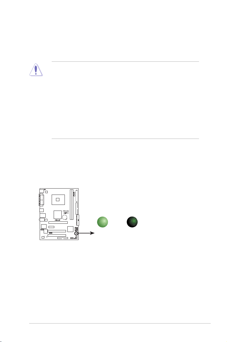
Onboard LED
The motherboard comes with a standby power LED that lights up to indicate that
the system is ON, in sleep mode, or in soft-off mode. This is a reminder that you
should shut down the system and unplug the power cable before removing or
plugging in any motherboard component.
P5V-VM
ULTRA
P5V-VM ULTRA Onboard LED
SB_PWR
ON
Standby
Power
OFF
Powered
Off
Page 16
1-6 Chapter 1: Product Introduction
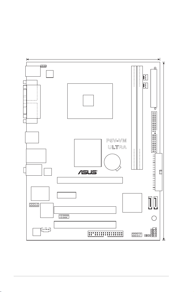
1.5 Motherboard Overview
1.5.1 Motherboard layout
LGA775
VIA
P4M890
VIA
VT8237A
18.3cm(7.2in)
24.4cm(9.6in)
DDR2 DIMM1 (64 bit,240-pin module)
DDR2 DIMM
2
(64 bit,240-pin module)
PCIEX16
PCI1
PCI2
PCIEX1_1
4Mb
BIOS
AAFP
CD
ALC660
USB78
USB56
SATA1
SATA2
CR2032 3V
Lithium Cell
CMOS Power
CLRTC
SPEAKER
F_PANEL
SUPER I/O
REALTEK
SB_PWR
FLOPPY
EATXPWR
PRI_IDE
CHA_FAN CPU_FAN
PS2_USB_PWR
ATX12V
SEC_IDE
PS/2KBMS
T: Mouse
B: Keyboard
LAN_USB34
COM1
PARALLEL PORT
VGA1
Below:Mic In
Center:Line Out
Top:Line In
USB12
P5V-VM
ULTRA
Page 17
ASUS P5V-VM Ultra Motherboard 1-7
P5V-VM
ULTRA
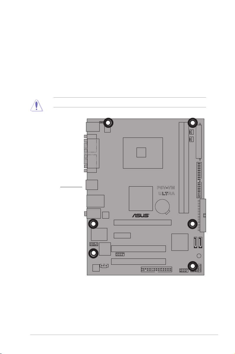
Do not overtighten the screws! Doing so may damage the motherboard.
1.5.2 Placement direction
When installing the motherboard, make sure that you place it into the chassis in the
correct orientation. The edge with external ports goes to the rear part of the chassis
as indicated in the image below.
1.5.3 Screw holes
Place six (6) screws into the holes indicated by circles to secure the motherboard
to the chassis.
Place this side
towards
the rear of the
chassis
Page 18
1-8 Chapter 1: Product Introduction
1.6.1 Installling the CPU
To install a CPU:
1. Locate the CPU socket on the motherboard.
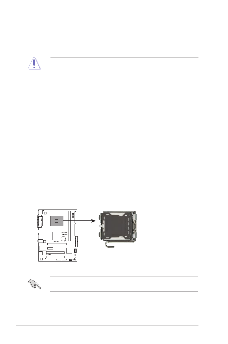
1.6 Central Processing Unit (CPU)
The motherboard comes with a surface mount LGA775 socket designed for the
Intel® Core™2 Extreme / Core™2 Duo / Pentium® D / Pentium® 4 / Celeron® D Processors.
•
Your boxed Intel® Core™2 Extreme / Core™2 Duo / Pentium® D /
Pentium® 4 / Celeron® D Processors package should come with
installation instructions for the CPU, fan and heatsink assembly.
If the instructions in this section do not match the CPU
documentation, follow the latter.
• Upon purchase of the motherboard, make sure that the PnP cap
is on the socket and the socket pins are not bent. Contact your
retailer immediately if the PnP cap is missing, or if you see any
damage to the PnP cap/socket pins/motherboard components.
ASUS will shoulder the cost of repair only if the damage is shipment/
transit-related.
• Keep the cap after installing the motherboard. ASUS will process
Return Merchandise Authorization (RMA) requests only if the
motherboard comes with the cap on the LGA775 socket.
•
The product warranty does not cover damage to the socket pins
resulting from incorrect CPU installation/removal, or misplacement/
loss/incorrect removal of the PnP cap.
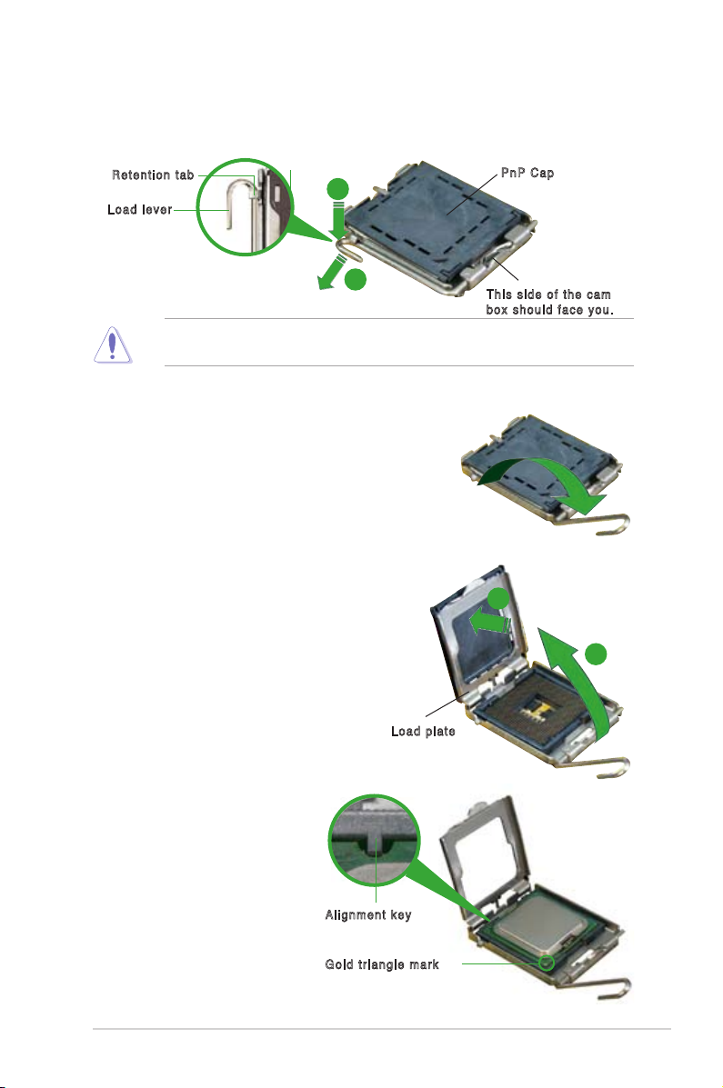
Before installing the CPU, make sure that the socket box is facing towards you
and the load lever is on your left.
P5V-VM
ULTRA
P5V-VM ULTRA CPU Socket 775
Page 19
ASUS P5V-VM Ultra Motherboard 1-9
3. Lift the load lever in the direction of
the arrow to a 135º angle.
4. Lift the load plate with your thumb
and forenger to a 100º angle (A),
then push the PnP cap from the load
plate window to remove (B).
To prevent damage to the socket pins, do not remove the PnP cap unless you
are installing a CPU.
5. Position the CPU over
the socket, making sure
that the gold triangle is
on the bottom-left corner
of the socket. The socket
alignment key should t into
the CPU notch.
2. Press the load lever with your thumb (A) and move it to the left (B) until it is
released from the retention tab.
Ret e nti o n tab
Loa d le v er
Thi s si d e of t h e c a m
box sho u ld fac e yo u .
PnP Ca p
A
B
Loa d pl a te
A
B
Ali g nme n t key
Gol d tr i an gle m ark
Page 20
1-10 Chapter 1: Product Introduction
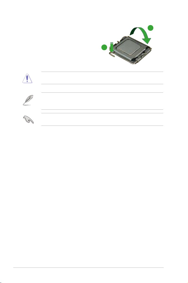
The CPU ts in only one correct orientation. DO NOT force the CPU into the
socket to prevent bending the connectors on the socket and damaging the CPU!
6. Close the load plate (A), then push
the load lever (B) until it snaps into
the retention tab.
A
B
The motherboard supports Intel® LGA775 processors with the Intel® Enhanced
Memory 64 Technology (EM64T), Enhanced Intel SpeedStep® Technology
(EIST), and Hyper-Threading Technology.
If you install a dual-core CPU, make sure to connect the chassis fan cable to
CHA_FAN connector for system stability.
Page 21
ASUS P5V-VM Ultra Motherboard 1-11
1.6.2 Installling the CPU heatsink and fan
The
Intel® Core™2 Extreme / Core™2 Duo / Pentium® D / Pentium® 4 / Celeron® D
Processors
require a specially designed heatsink and fan assembly to ensure
optimum thermal condition and performance.performance.
• Install the motherboard to the chassis before you install the CPU fan
and heatsink assembly
• When you buy a boxed Intel® Core™2 Extreme / Core™2 Duo / Pentium®
D / Pentium® 4 / Celeron® D LGA775 processor, the packageincludes
the CPU fan and heatsink assembly. If you buy a CPU separately,
make sure that you use only Intel®‑certied multi‑directional heatsink
and fan.
• Your I Intel® Core™2 Extreme / Core™2 Duo / Pentium® D / Pentium® 4 /
Celeron® D LGA775 heatsink and fan assembly comes in a push-pin
design and requires no tool to install.
If you purchased a separate CPU heatsink and fan assembly, make sure that
a Thermal Interface Material is properly applied to the CPU heatsink or CPU
before you install the heatsink and fan assembly.
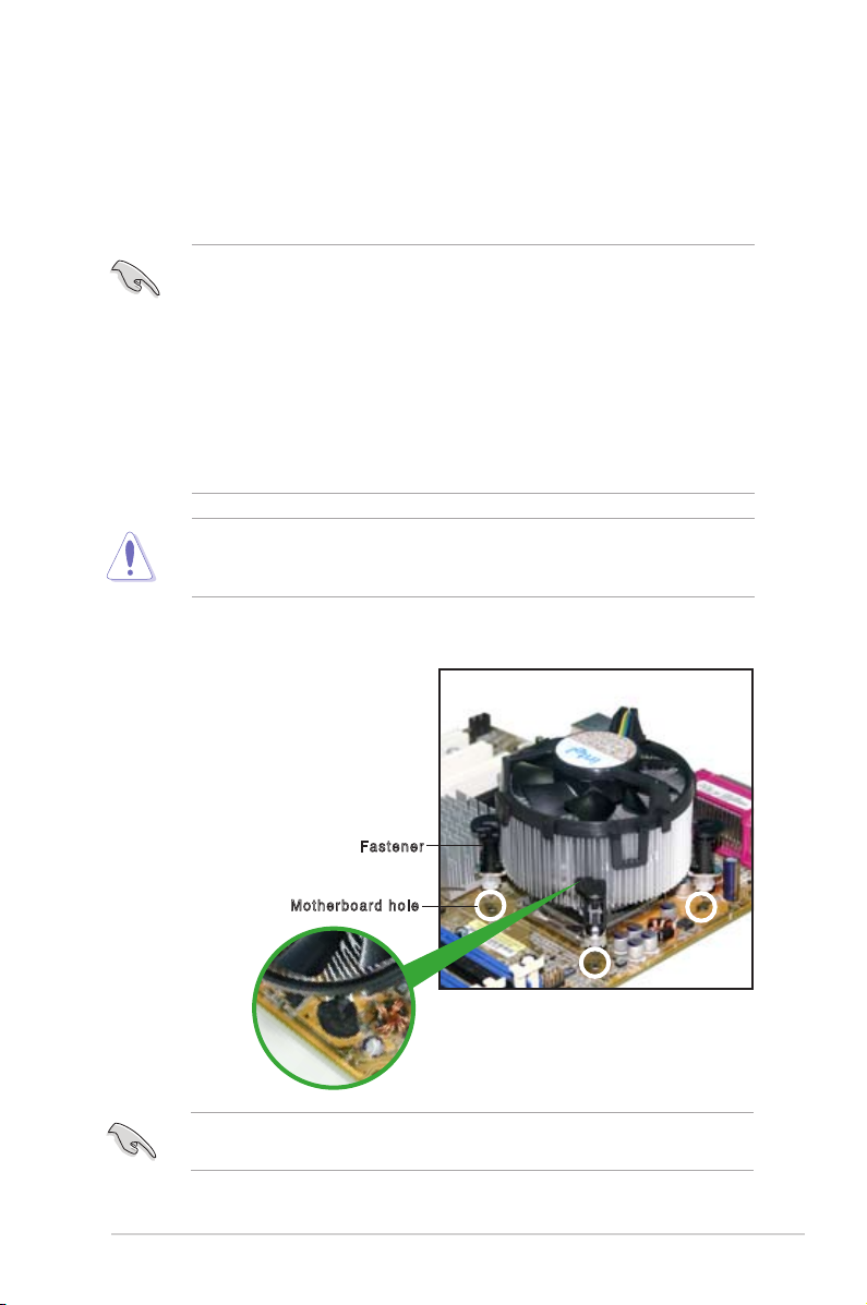
To install the CPU heatsink and fan:
1. Place the heatsink on top of the
installed CPU, making sure that the
four fasteners match the holes on
the motherboard.
Fas t ene r
Mot h erb o ar d ho l e
Make sure each fastener is oriented as shown, with the narrow groove directed
outward.
Page 22
1-12 Chapter 1: Product Introduction
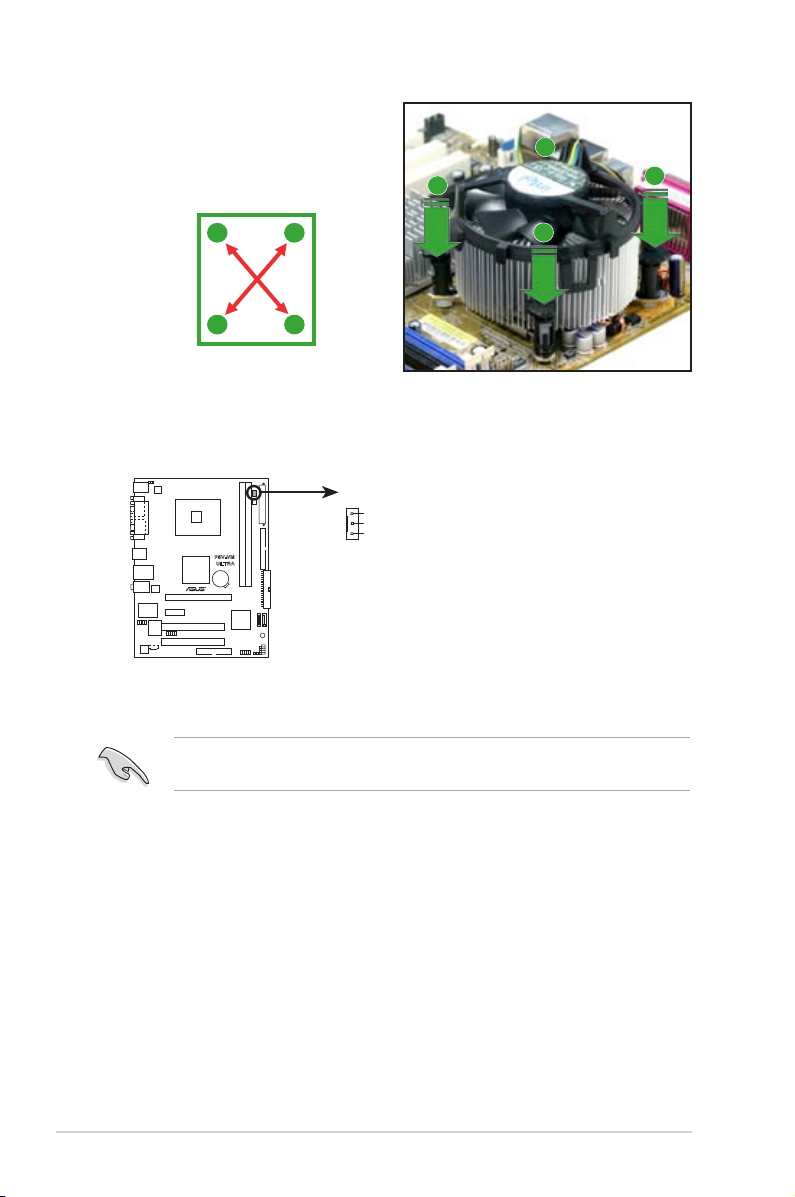
Do not forget to connect the CPU fan connector! Hardware monitoring errors
can occur if you fail to plug this connector.
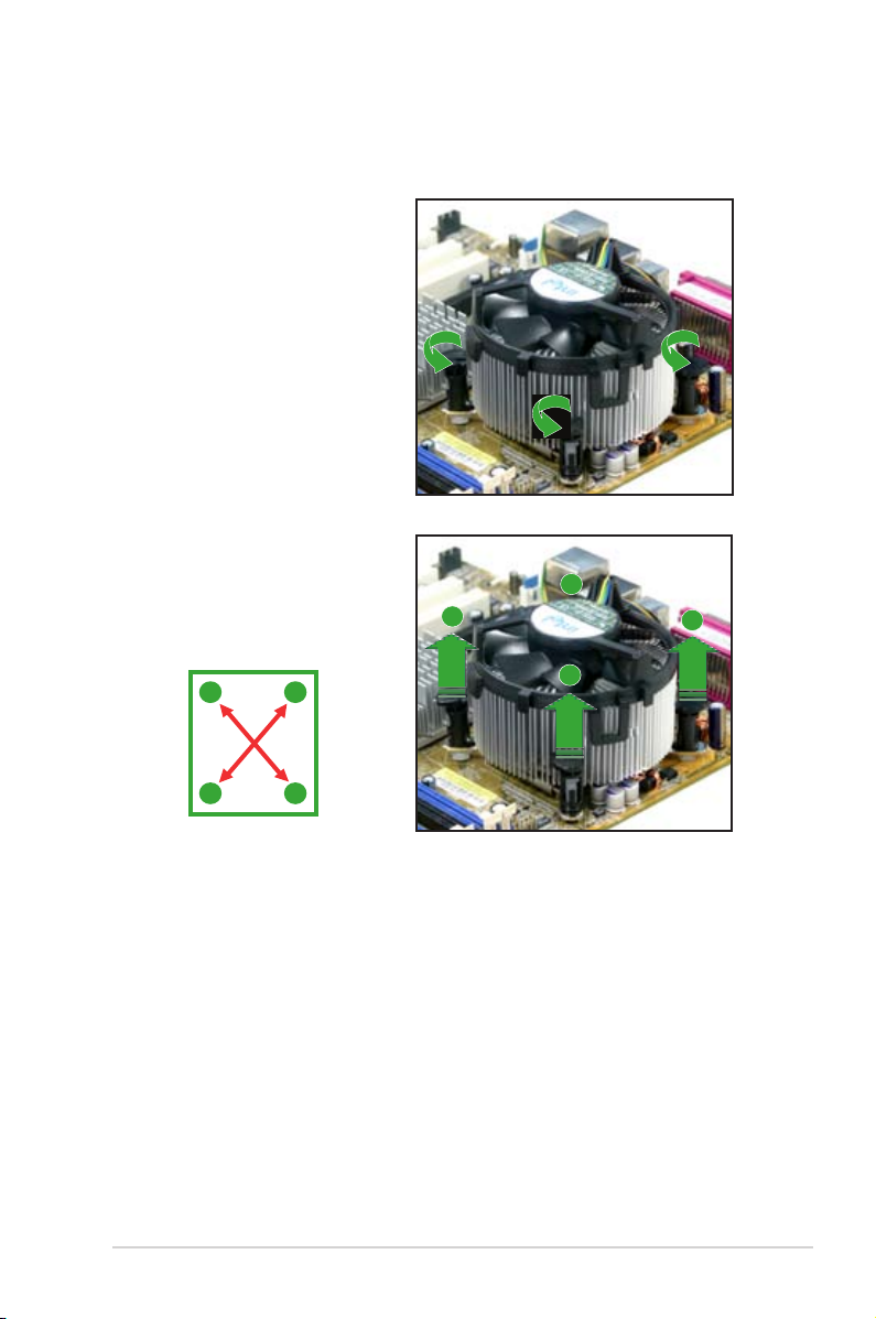
3. When the fan and heatsink assembly is in place, connect the CPU fan cable
to the connector on the motherboard labeled CPU_FAN.
2. Push down two fasteners at a time
in a diagonal sequence to secure
the heatsink and fan assembly in
place.
A
A
B
B
B
B
A
A
P5V-VM
ULTRA
P5V-VM ULTRA CPU Fan Connector
n
GND
Rotatio
+12V
CPU_FAN
Page 23
ASUS P5V-VM Ultra Motherboard 1-13
1.6.3 Uninstalling the CPU heatsink and fan
To uninstall the CPU heatsink and fan:
1. Disconnect the CPU fan cable
from the connector on the
motherboard.
2. Rotate each fastener
counterclockwise.
3. Pull up two fasteners at a
time in a diagonal sequence
to disengage the heatsink
and fan assembly from the
motherboard.
A
A
B
B
B
B
A
A
Page 24
1-14 Chapter 1: Product Introduction
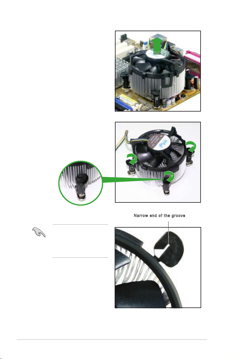
4. Remove the heatsink and fan
assembly from the motherboard.
5. Rotate each fastener clockwise
to reset the orientation.
The narrow end of the
groove should point outward
after resetting. (The photo
shows the groove shaded
for emphasis.)
Nar r ow e nd of t he g roo v e
Page 25

ASUS P5V-VM Ultra Motherboard 1-15
1.7 System memory
1.7.1 Overview
The motherboard comes with four Double Data Rate 2 (DDR2) Dual Inline Memory
Modules (DIMM) sockets.
A DDR2 module has the same physical dimensions as a DDR DIMM but has a
240-pin footprint compared to the 184-pin DDR DIMM. DDR2 DIMMs are notched
differently to prevent installation on a DDR DIMM socket.
The gure illustrates the location of the DDR2 DIMM sockets:
1.7.2 Memory congurations
You may install 256 MB, 512 MB and 1 GB unbuffered DDR2 DIMMs into the
DIMM sockets.
For optimum compatibility, we recommend that you obtain memory modules
from qualied vendors. See the Qualied Vendors List (QVL) on the next page.
P5V-VM
ULTRA
P5V-VM ULTRA
240-pin DDR DIMM Sockets
112
Pi
n
s
128
Pi
ns
Page 26

1-16 Chapter 1: Product Introduction
Qualied DDR2 533 DIMMs
The following table lists the DDR2 533 (PC2-4200) memory modules that have
been tested and qualied for use with this motherboard.
Obtain DDR DIMMs only from qualied vendors for better system performance.
Legend:
A -
Supp ort s o ne mod u le ins ert ed int o eith er slo t a s a Si n gle -ch ann el mem o ry
conguration.
B -
Supports two pairs of modules inserted into either the yellow slot or the black slot.
SS -
Single-sided
DS -
Double-sided
DIMM support
Size Vendor Model Brand Side(s) Component A* B*
256MB Kingston KVR533D2N4/256 Elpida SS E5116AB-5C-E • •
256MB Kingston KVR533D2N4/256 Elpida SS E5116AF-5C-E • •
512MB Kingston KVR533D2N4/512 Hynix DS HY5PS56821 • •
512MB Kingston KVR533D2N4/512 Inneon SS HYB18T512800AF3733336550 • •
1G Kingston KVR533D2N4/1G Kingston DS D6408TE7BL-37 • •
1G Kingston KVR533D2N4/1G Micron DS 5YD11D9GCT • •
256MB Samsung M378T3253FG0-CD5 Samsung SS K4T56083QF-GCD5 • •
512MB Samsung M378T6553BG0-CD5 Samsung SS K4T51083QB-GCD5 • •
256MB Inneon HYS64T32000HU‑3.7‑A Inneon SS HYB18T512160AF‑3.7AFSS31270 • •
512MB Inneon HYS64T64000GU‑3.7‑A Inneon SS HYB18T512800AC37SSS11511 • •
512MB Inneon HYS64T64000HU‑3.7‑A Inneon SS HYB18T512800AF37FSS29334 • •
512MB Inneon HYS64T64000HU‑3.7‑A Inneon SS HYB18T512800AF37SSS12079 • •
512MB Micron MT 16HTF6464AG-53EB2 Micron DS D9BOM • •
512MB Micron MT 16HTF6464AG-53EB2 Micron DS Z9BQT • •
1G Micron MT 16HTF12864AY-53EA1 Micron DS D9CRZ • •
512MB Corsair VS512MB533D2 Corsair DS MIII0052532M8CEC • •
512MB Elpida EBE51UD8ABFA-5C-E Elpida SS E5108AB-5C-E • •
512MB Kingmax KLBC28F-A8KB4 Kingmax SS KKEA88B4IAK-37 • •
256MB Kingmax KLBB68F-36EP4 Elpida SS E5116AB-5C-E • •
512MB Kingmax KLBC28F-A8EB4 Elpida SS E5108AE-5C-E • •
512MB PQI MEAB-323LA PQI SS D2-E04180W025 • •
1G PQI MEAB-423LA PQI DS D2-E04230W107 • •
512MB AENEON AET660UD00-370A98Z AENEON SS AET93F370A G 0513 • •
256MB AENEON AET560UD00-370A98Z AENEON SS AET94F370AWVV34635G0520 • •
512MB AENEON AET660UD00-370A98Z AENEON SS AET93F370A 3VV36328G 0522 • •
512MB AENEON AET660UD00-370A98X AENEON SS AET93F370A 0518 • •
512MB AENEON AET660UD00-370A88S AENEON DS AET82F370A 0550 • •
1G AENEON AET760UD00-370A98Z AENEON DS AET93F370A 0551 • •
2G AENEON AET860UD00-370A08X AENEON DS AET03F370AFVV26176G 0542 • •
Visit the ASUS website (www.asus.com) for the latest DDR2 533 Qualied
Vendors List.
Page 27

ASUS P5V-VM Ultra Motherboard 1-17
1.7.4 Installing a DIMM
Unplug the power supply before adding or removing DIMMs or other
system components. Failure to do so can cause severe damage to both the
motherboard and the components.
To install a DIMM:
1. Unlock a DIMM socket by
pressing the retaining clips
outward.
2. Align a DIMM on the socket
such that the notch on the DIMM
matches the break on the socket.
3. Firmly insert the DIMM into the
socket until the retaining clips
snap back in place and the DIMM
is properly seated.
1.7.5 Removing a DIMM
Follow these steps to remove a DIMM.
1. Simultaneously press the retaining
clips outward to unlock the DIMM.
2. Remove the DIMM from the socket.
• A DDR2 DIMM is keyed with a notch so that it ts in only one direction. Do
not force a DIMM into a socket to avoid damaging the DIMM.
• The DDR2 DIMM sockets do not support DDR DIMMs. DO not install DDR
DIMMs to the DDR2 DIMM sockets.
Support the DIMM lightly with
your ngers when pressing the
retaining clips. The DIMM might
get damaged when it ips out with
extra force.
Unl o cke d r etai n ing cli p
DDR 2 DI M M notc h
1
2
3
DDR 2 DI M M notc h
1
2
1
Page 28

1-18 Chapter 1: Product Introduction
1.8 Expansion slots
In the future, you may need to install expansion cards. The following sub-sections
describe the motherboard slots and the expansion cards that they support.
1.8.1 Installing an expansion card
Follow these steps to install an expansion card.
1. Before installing the expansion card, read the documentation that came with it
and make the necessary hardware settings for the card.
2.
Remove the system unit cover (if your motherboard is already installed
in a chassis).
3. Remove the bracket opposite the slot that you intend to use. Keep the screw
for later use.
4. Align the c ard con ne ctor wi th the slot and press firmly until t he card is
completely seated on the slot.
5. Secure the card to the chassis with the screw you removed earlier.
6. Replace the system cover.
1.8.2 Conguring an expansion card
After installing the expansion card, congure the card by adjusting the software settings.
1. Turn on the system and change the necessary BIOS settings, if any. See
Chapter 2 for information on BIOS setup.
2. Assign an IRQ to the card. Refer to the tables on the next page.
3. Install the software drivers for the expansion card.
Make sure to unplug the power cord before adding or removing expansion
car d s . Fa ilur e to d o so ma y ca use y ou p h y sica l in j u ry a n d da mage
motherboard components.
Page 29

ASUS P5V-VM Ultra Motherboard 1-19
Standard Interrupt Assignments
IRQ assignments for this motherboard
When using PCI cards on shared slots, ensure that the drivers support
“Share IRQ” or that the cards do not need IRQ assignments; otherwise,
conflicts will arise between the two PCI groups, making the system unstable
and the card inoperable.
IRQ Priority Standard Function
0 1 System Timer
1 2 Keyboard Controller
2 N/A N/A
3 11 IRQ Holder for PCI Steering
4 12 Communications Port (COM1)
5 13 IRQ Holder for PCI Steering
6 14 Floppy Disk Controller
7 15 Printer Port (LPT1)
8 3 System CMOS/Real Time Clock
9 4 Microsoft ACPI-Compliant System
10 5 IRQ Holder for PCI Steering
11 6 IRQ Holder for PCI Steering
12 7 PS/2 Compatible Mouse Port
13 8 Numeric Data Processor
14 9 Primary IDE Channel
15 10 Secondary IDE Channel
INT A INT B INT C INT D
PCI slot 1 shared –– –– ––
PCI slot 2 –– shared –– ––
OnBoard VGA shared –– –– ––
Page 30
1-20 Chapter 1: Product Introduction
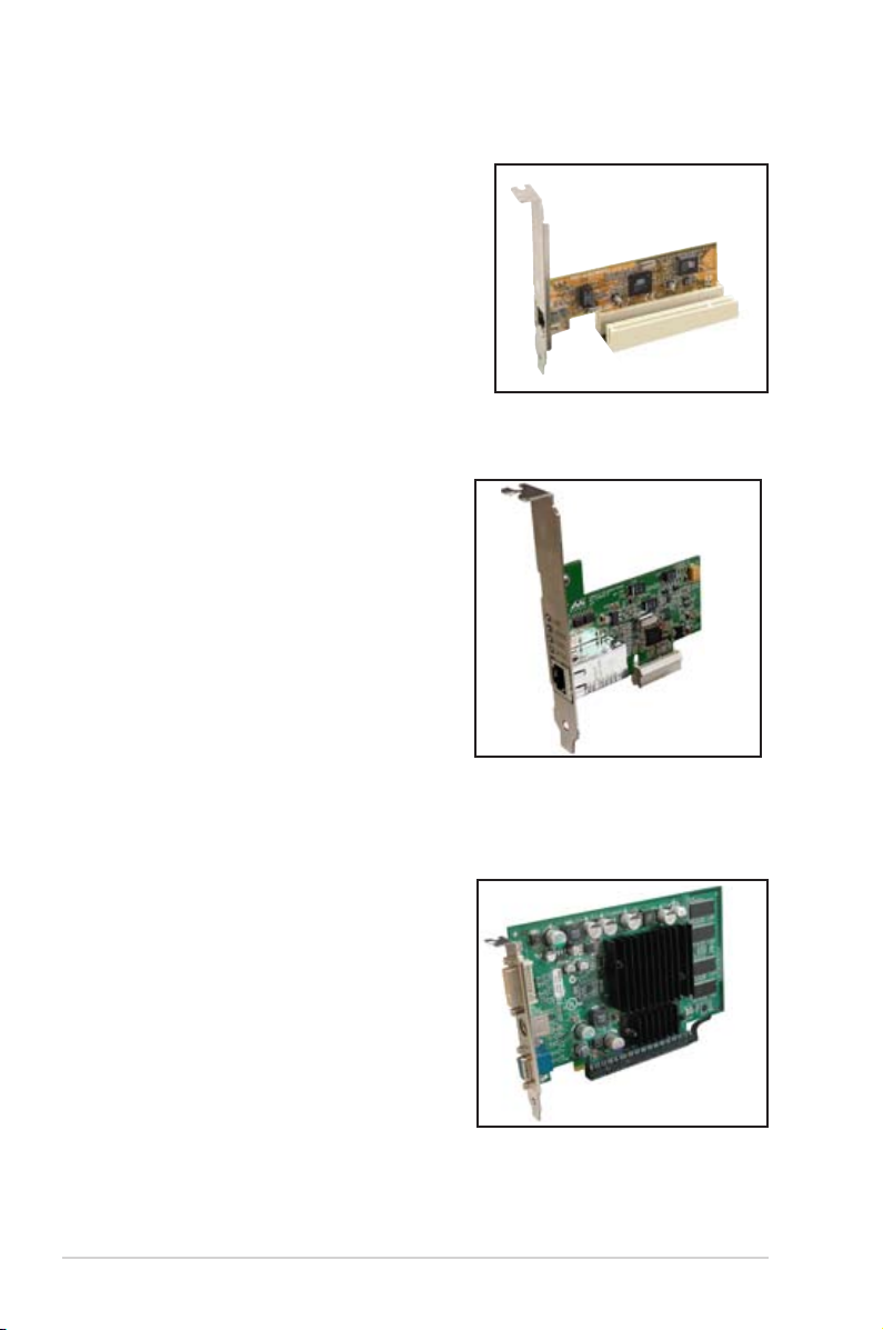
1.8.3 PCI slots
Th e P CI slots sup port LAN, S CSI , U SB,
and other PCI cards that comply with PCI
specications. The gure shows a LAN card
installed on a PCI slot.
1.8.4 PCI Express x1 slot
This motherboard supports PCI Express
x1 network cards, SCSI cards and other
cards that comply with the PCI Express
specications. The gure shows a network
card installed on the PCI Express x1 slot.
1.8.5 PCI Express x16 slot
This motherboard supports PCI Express x16
graphic cards that comply with the PCI
Express specications. The gure shows a
graphics card installed on the PCI Express
x16 slot.
Page 31

ASUS P5V-VM Ultra Motherboard 1-21
1.9 Jumpers
1. Clear RTC RAM (CLRTC)
This jumper allows you to clear the Real Time Clock (RTC) RAM in CMOS.
You can clear the CMOS memory of date, time, and system setup parameters
by erasing the CMOS RTC RAM data. The RAM data in CMOS, that include
system setup information such as system passwords, is powered by the
onboard button cell battery.
To erase the RTC RAM:
1. Turn OFF the computer and unplug the power cord.
2. Remove the onboard battery.
3. Move the jumper cap from pins 1-2 (default) to pins 2-3. Keep the cap on
pins 2-3 for about 5~10 seconds, then move the cap back to pins 1-2.
4. Replace the battery.
5. Plug the power cord and turn ON the computer.
6. Hold down the <Del> key during the boot process and enter BIOS setup
to re-enter data.
Except when clearing the RTC RAM, never remove the cap on the CLRTC
jumper default position. Removing the cap will cause system boot failure!
P5V-VM
ULTRA
P5V-VM ULTRA Clear RTC RAM
CLRTC
Normal Clear CMOS
(Default)
2 31 2
Page 32

1-22 Chapter 1: Product Introduction
2. USB device wake-up (3-pin PS2_USB_PWR)
Set this jumper to +5V to wake up the computer from S1 sleep mode (CPU
stopped, DRAM refreshed, system running in low power mode) using the
connected USB devices. Set to +5VSB to wake up from S3 and S4 sleep mode
(no power to CPU, DRAM in slow refresh, power supply in reduced power mode).
• The USB device wake-up feature requires a power supply that can provide
500mA on the +5VSB lead for each USB port; otherwise, the system would
not power up.
• The total current consumed must NOT exceed the power supply capability
(+5VSB) whether under normal condition or in sleep mode.
P5V-VM
ULTRA
P5V-VM ULTRA USB Device Wake Up
3
2
21
+5V +5VSB
PS2_USB_PWR
(Default)
Page 33

ASUS P5V-VM Ultra Motherboard 1-23
1.10 Connectors
This section describes and illustrates the rear panel and internal connectors on the
motherboard.
1.10.1 Rear panel connectors
1. PS/2 mouse port (green).
This 6-pin port is for a PS/2 mouse.
2. Parallel port.
This 25-pin port connects a parallel printer, a scanner, or other devices.
3. LAN (RJ-45) port.
This port allows connection to a Local Area Network (LAN)
through a network hub.
4. Line In port.
This Line In (light blue) port connects a tape player or other
audio sources. In 4 or 6-channel mode, the function of this port becomes Back
Surround.
5. Line Out port.
This Line Out (lime) port connects a headphone or a speaker.
In 4 or 6-channel mode, the function of this port becomes Front Speaker Out.
6. Microphone port.
This Mic (pink) port connects a microphone. In 6-channel
mode, the function of this port becomes Center/LFE.
Audio ports function variation
Audio ports Headphone /2-Channel 4-Channel 6-Channel
Light Blue Line In Back Surround Back Surround
Lime Line Out Front Speaker Out Front Speaker Out
Pink Mic In Mic In Center/LFE
The functions of the Line Out, Line In, and Microphone ports change when you
select the 4 or 6-channel audio conguration as shown in the following table.
1
11 7
2 3
10
4
5
6
9
8
Page 34

1-24 Chapter 1: Product Introduction
7. USB 2.0 ports 3 and 4.
These two 4-pin Universal Serial Bus (USB) ports are
available for connecting USB 2.0 devices.
8. USB 2.0 ports 1 and 2.
These two 4-pin Universal Serial Bus (USB) ports are
available for connecting USB 2.0 devices
9. Video Graphics Adapter port.
This 15-pin port is for a VGA monitor or other
VGA-compatible devices.
10. Serial port.
This 9-pin COM1 port is for pointing devices or other serial devices.
11. PS/2 keyboard port (purple).
This port is for a PS/2 keyboard.
1.10.2 Internal connectors
1. Floppy disk drive connector (34-1 pin FLOPPY)
This connector is for the provided oppy drive (FDD) signal cable. Insert one
end of the cable to this connector, then connect the other end to the signal
connector at the back of the oppy disk drive.
Pin 5 on the connector is removed to prevent incorrect cable connection when
using an FDD cable with a covered Pin 5.
P5V-VM
ULTRA
P5V-VM ULTRA
Floppy Disk Drive Connector
NOTE: Orient the red markings on
the floppy ribbon cable to PIN 1.
PIN1
FLOPPY
Page 35

ASUS P5V-VM Ultra Motherboard 1-25
Single device Cable-Select or Master - Black
Two devices Cable-Select Master Black
Slave Gray
Master Master
Slave Slave
2. IDE connectors (40-1 pin PRI_IDE, SEC_IDE)
The onboard IDE connectors are for Ultra DMA 133/100/66 signal cables.
There are three connectors on each Ultra DMA 133/100/66 signal cable:
blue, black, and gray. Connect the blue connector to the motherboard’s IDE
connector, then select one of the following modes to congure your device(s).
• Pin 20 on the IDE connector is removed to match the covered hole on the
Ultra DMA cable connector. This prevents incorrect insertion when you
connect the IDE cable.
• Use the 80-conductor IDE cable for Ultra DMA 133/100/66 IDE devices.
If any device jumper is set as “Cable-Select,” make sure all other device
jumpers have the same setting.
Black or gray
Drive jumper Mode Cable
setting of devices connector
P5V-VM
ULTRA
P5V-VM ULTRA IDE Connectors
SEC_IDE
NOTE: Orient the red markings
(usually zigzag) on the IDE
ribbon cable to PIN 1.
PRI_IDE
PIN 1
Page 36

1-26 Chapter 1: Product Introduction
4. CPU and chassis fan connectors (3-pin CPU_FAN, CHA_FAN)
The fan connectors support cooling fans of 350mA~740mA (8.88W max.) or
a total of 1A~2.22A (26.64W max.) at +12V. Connect the fan cables to the fan
connectors on the motherboard, making sure that the black wire of each cable
matches the ground pin of the connector.
Do not forget to connect the fan cables to the fan connectors. Insufcient air
ow within the system can damage the motherboard components. These are
not jumpers! DO NOT place jumper caps on the fan connectors!
3. Internal audio connector (4-pin CD)
This connector allows you to receive stereo audio input from sound sources
such as a CD-ROM, TV tuner, or MPEG card.
P5V-VM
ULTRA
P5V-VM ULTRA Internal Audio Connector
CD
(black)
Right Audio Channel
Left Audio Channel
Ground
Ground
P5V-VM
ULTRA
P5V-VM ULTRA Fan Connectors
n
GND
Rotatio
+12V
CPU_FAN
n
GND
Rotatio
+12V
CHA_FAN
Page 37

ASUS P5V-VM Ultra Motherboard 1-27
5. ATX power connectors (24-pin EATXPWR, 4-pin ATX12V)
These connectors are for ATX power supply plugs. The plugs from the power
supply are designed to t these connectors in only one orientation. Find the
proper orientation and push down rmly until the connectors t completely.
• Do not forget to connect the 4-pin ATX +12V power plug; otherwise, the
system does not boot up.
• Make sure that your ATX 12V power supply can provide 12A on the +12V
lead and at least 1A on the +5-volt standby lead (+5VSB). The minimum
recommended wattage is 300 W, or 350 W for a fully congured system.
The sy stem c an become unstable or w ill no t boot up if the p ower i s
inadequate.
6. Speaker out connector (4-pin SPEAKER)
This connector is for the case-mounted speaker and allows you to hear system
beeps and warnings.
P5V-VM
ULTRA
P5V-VM ULTRA ATX Power Connectors
ATX12V
+12V DC
GND
+12V DC
GND
EATXPWR
+3 Volts
+3 Volts
Ground
+5 Volts
+5 Volts
Ground
Ground
Power OK
+5V Standby
+12 Volts
-5 Volts
+5 Volts
+3 Volts
-12 Volts
Ground
Ground
Ground
PSON#
Ground
+5 Volts
+12 Volts
+3 Volts
+5 Volts
Ground
P5V-VM
ULTRA
P5V-VM ULTRA Speaker Out Connector
SPEAKER
+5V
GND
GND
Speaker Out
1
Page 38
1-28 Chapter 1: Product Introduction
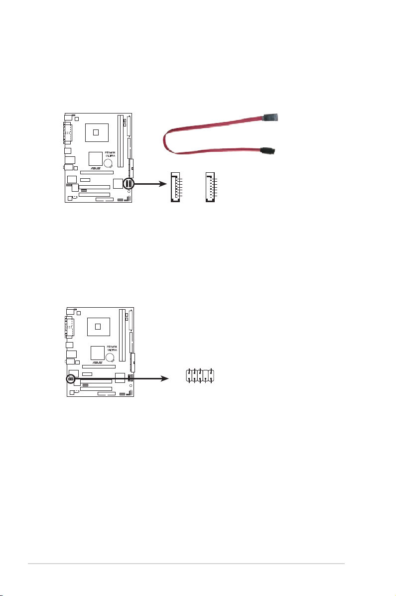
7. Serial ATA connectors (7-pin SATA1, SATA2)
These connectors support the thin Serial ATA cables for Serial ATA hard
disks. If you installed Serial ATA hard disks, you may create a RAID 0,
RAID 1, or JBOD conguration.
8. Front panel audio connector (10-1 pin AAFP)
This interface for the front panel audio cable allows convenient connection and
control of audio devices.
P5V-VM
ULTRA
P5V-VM ULTRA SATA Connectors
GND
RSATA_TXP1
RSATA_TXN1
GND
RSATA_RXP1
RSATA_RXN1
GND
GND
RSATA_TXP2
RSATA_TXN2
GND
RSATA_RXP2
RSATA_RXN2
GND
SATA1
SATA2
P5V-VM
ULTRA
P5V-VM ULTRA
Analog Front Panel Connector
AAFP
Azalia
compliant definition
SENSE2_RETUR
PORT1 L
PORT2 R
PORT2 L
SENSE1_RETUR
SENSE_SEND
PORT1 R
PRESENCE#
GND
Page 39
ASUS P5V-VM Ultra Motherboard 1-29
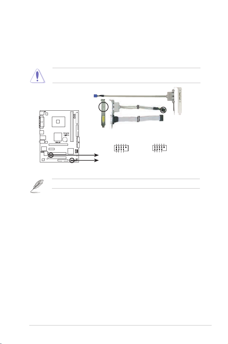
9. USB connectors (10-1 pin USB56, USB78)
These connectors are for USB 2.0 ports. Connect the USB module cable to
any of these connectors, then install the module to a slot opening at the back of
the system chassis. These USB connectors comply with USB 2.0 specication
that supports up to 480 Mbps connection speed.
NEVER connect a
1394 cable
to the USB connectors. Doing so will damage
the motherboard!
The USB module is purchased separately.
P5V-VM
ULTRA
P5V-VM ULTRA USB 2.0 Connectors
USB78
USB+5V
USB_P8-
USB_P8+
GND
NC
USB+5V
USB_P7-
USB_P7+
GND
1
USB56
USB+5V
USB_P6
USB_P6
GND
NC
USB+5V
USB_P5-
USB_P5+
GND
-
+
1
Page 40

1-30 Chapter 1: Product Introduction
10. System panel connector (10-1 pin F_PANEL)
This connector supports several system chassis-mounted functions.
•
System power LED (2-pin PLED)
This 3-pin connector is for the system power LED. Connect the chassis power
LED cable to this connector. The system power LED lights up when you turn
on the system power, and blinks when the system is in sleep mode.
•
Power/Soft-off button (2-pin PWRSW)
This connector is for the system power button. Pressing the power button
turns the system ON or puts the system in SLEEP or SOFT-OFF mode
depending on the BIOS settings. Pressing the power switch for more than
four seconds while the system is ON turns the system OFF.
• Hard disk drive activity (2-pin IDELED)
This 2-pin connector is for the HDD Activity LED. Connect the HDD Activity
LED cable to this connector. The IDE LED lights up or ashes when data is
read from or written to the HDD.
•
Reset button (2-pin RESET)
This connector is for the chassis-mounted reset button for system reboot
without turning off the system power.
P5V-VM
ULTRA
P5V-VM ULTRA System Panel Connector
F_PANEL
PLED-
PWR
PLED+
Ground
GND Reset
IDELED+
IDELED-
IDE LED RESET
PLED PWRSW
1
Page 41

Chapter 2
This chapter tells how to change system settings
through the BIOS Setup menus, and provides
detailed descriptions of the BIOS parameters.
BIOS Information
Page 42

2-2 Chapter 2: BIOS Information
2.1 Managing and Updating Your BIOS
The following utilities allow you to manage and update the motherboard Basic
Input/Output System (BIOS) setup.
1.
AFUDOS
(Updates the BIOS in DOS mode using a bootable oppy disk.)
2.
ASUS EZ Flash
(Updates the BIOS using a oppy disk during POST.)
3.
ASUS CrashFree BIOS 2
(Updates the BIOS using a bootable oppy disk or the
motherboard support CD).
Refer to the corresponding section for each utility.
2.1.1 Creating a bootable oppy disk
1. Do either one of the following to create a bootable oppy disk.
DOS environment
Insert a 1.44MB oppy disk into the drive. At the DOS prompt, type:
format A:/S
then press <Enter>.
Windows® XP environment
a. Insert a 1.44MB oppy disk into the oppy disk drive.
b. From your Windows® desktop, click on
Start
, then select
My Computer
.
c. Select the
3 1/2 Floppy Drive
icon.
d. Click
File
from the menu, then select
Format
. A
Format 3 1/2 Floppy Disk
window appears.
e. Select
Create an MS-DOS startup disk
from the format options eld, then
click
Start
.
2. Copy the original (or the latest) motherboard BIOS to the bootable oppy disk.
2.1.2 Using AFUDOS to copy the current BIOS
The AFUDOS.EXE utility can also be used to copy the current system BIOS
settings to a oppy or hard disk. The copy can be used as a backup in case the
system BIOS fails or gets corrupted.
1. At the DOS prompt, type the command line:
afudos /o[lename]
where “lename” can be any user-provided lename of not more than eight
alphanumeric characters for the main filename and three alphanumeric
characters for the extension name.
Press <Enter>.
• Save a copy of the original motherboard BIOS le to a bootable oppy disk
in case you need to restore the BIOS in the future. Copy the original
motherboard BIOS using the AFUDOS utility.
• Refer to the system builder’s website for details about updating the BIOS.
Page 43

ASUS P5V-VM Ultra Motherboard 2-3
2. The utility will copy the current system BIOS by default to the oppy disk. Make
sure that the oppy disk is not write-protected and has enough space (at least
600KB) to store the le.
The BIOS information on the screen is for reference only. What you see on your
screen may not be exactly the same as shown.
When the BIOS copy process is complete, the utility returns to the DOS prompt.
A:\>afudos /oMYBIOS03.rom
AMI Firmware Update Utility - Version 1.10
Copyright (C) 2002 American Megatrends, Inc. All rights reserved.
Readingash.....done
A:\>
2.1.3 Using AFUDOS to update the BIOS
The AFUDOS is a DOS-based application that lets you update the BIOS le using
a bootable oppy diskette. AFUDOS also allows you to copy the original BIOS le
to a oppy diskette.
To update the BIOS using the AFUDOS.EXE:
1. Download the latest BIOS le from the website provided by the system builder.
Main lename Extension name
A:\>afudos /oMYBIOS03.rom
AMI Firmware Update Utility - Version 1.10
Copyright (C) 2002 American Megatrends, Inc. All rights reserved.
Readingash.....0x0008CC00(9%)
Write the BIOS lename on a piece of paper. You need to type the exact BIOS
le name at the prompt.
2. Copy the AFUDOS.EXE utility from the support CD to the bootable oppy disk
that contains the BIOS le.
3. Boot the system from the oppy disk.
Page 44

2-4 Chapter 2: BIOS Information
4. At the DOS prompt, type the command line:
afudos /i[lename.rom]
where [lename.rom] means the latest (or original) BIOS le that you copied to
the bootable oppy disk.
5. Press <Enter>. The screen displays the status of the update process.
A:\>afudos /iP5V-VM.rom
AMI Firmware Update Utility - Version 1.10
Copyright (C) 2002 American Megatrends, Inc. All rights reserved.
Readingle.....done
Erasingash....done
Writingash....0x0008CC00(9%)
When the BIOS update process is complete, the utility returns to the DOS prompt.
A:\>afudos /iP5V-VM.rom
AMI Firmware Update Utility - Version 1.10
Copyright (C) 2002 American Megatrends, Inc. All rights reserved.
Readingle.....done
Erasingash....done
Writingash....0x0008CC00(9%)
Verifyingash..done
A:\>
DO NOT shut down or reset the system while updating the BIOS! Doing so can
cause system boot failure!
The BIOS information on the screen is for reference only. What you see on your
screen may not be exactly the same as shown.
6. Reboot the system from the hard disk.
Page 45

ASUS P5V-VM Ultra Motherboard 2-5
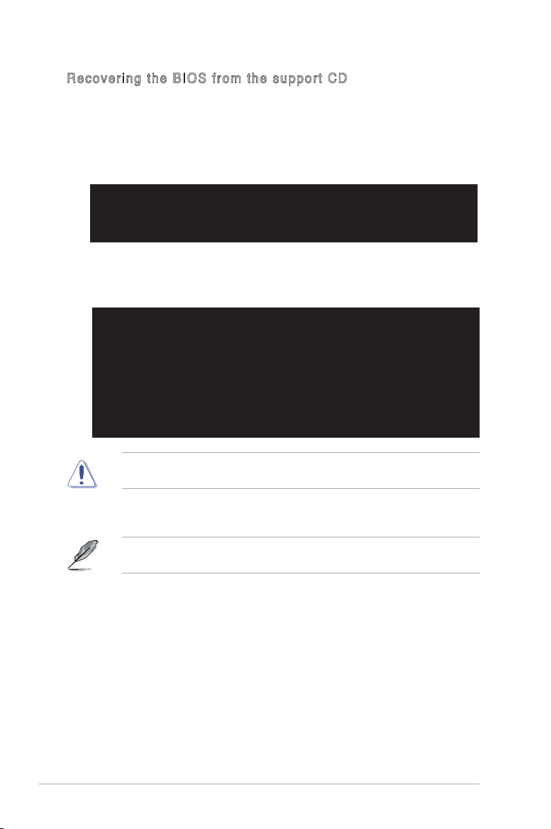
2.1.4 ASUS CrashFree BIOS 2 utility
The ASUS CrashFree BIOS 2 is an auto recovery tool that allows you to restore
the BIOS le when it fails or gets corrupted during the updating process. You can
update a corrupted BIOS le using the motherboard support CD or the oppy disk
that contains the updated BIOS le.
When found, the utility reads the BIOS le and starts ashing the corrupted
BIOS le.
4. Restart the system after the utility completes the updating process.
DO NOT shut down or reset the system while updating the BIOS! Doing so can
cause system boot failure!
Bad BIOS checksum. Starting BIOS recovery...
Checkingforoppy...
• Prepare the motherboard support CD or the oppy disk containing the
updated motherboard BIOS before using this utility.
• Make sure that you rename the original or updated BIOS le in the oppy
disk to P5V-VMUT.ROM.
Recover i n g t he BIOS f r o m a flo p p y d i sk
To recover the BIOS from a oppy disk:
1. Turn on the system.
2. Insert the oppy disk with the original or updated BIOS le to the
oppy disk drive.
3. The utility displays the following message and automatically checks
the oppy disk for the original or updated BIOS le.
Bad BIOS checksum. Starting BIOS recovery...
Checkingforoppy...
Floppy found!
Readingle“ P5V-VM.ROM”.Completed.
Startashing...
Page 46
2-6 Chapter 2: BIOS Information
Recov e r i n g t he BI O S f r o m the s u p p o r t CD
To recover the BIOS from the support CD:
1. Remove any oppy disk from the oppy drive, then turn on the system.
2. Insert the support CD to the optical drive.
3. The utility displays the following message and automatically checks the oppy
disk for the original or updated BIOS le.
When no oppy disk is found, the utility automatically checks the optical drive
for the original or updated BIOS le. The utility then updates the corrupted
BIOS le.
The recovered BIOS may not be the latest BIOS version for this motherboard.
Visit the ASUS website (www.asus.com) to download the latest BIOS le.
4. Restart the system after the utility completes the updating process.
DO NOT shut down or reset the system while updating the BIOS! Doing so can
cause system boot failure!
Bad BIOS checksum. Starting BIOS recovery...
Checkingforoppy...
Bad BIOS checksum. Starting BIOS recovery...
Checkingforoppy...
Floppy not Found!
Checking for CD-ROM...
CD-ROM found!
Readingle“ P5V-VM.ROM”.Completed.
Startashing...
Page 47

ASUS P5V-VM Ultra Motherboard 2-7
2.1.5 Using ASUS EZ Flash to update the BIOS
The ASUS EZ Flash feature allows you to easily update the BIOS without
having to go through the long process of booting from a oppy disk and
using a DOS-based utility. The EZ Flash is built-in the BIOS LPC chip so
it is accessible by simply pressing <Alt> + <F2> during the Power-On Self
Tests (POST).
To update the BIOS using ASUS EZ Flash:
1. Visit the system builder website to download the latest BIOS file for your
motherboard and rename it to
P5VVMUT.ROM
. Save the BIOS le to a oppy
disk.
2. Reboot the system.
4. Insert the floppy disk that contains the BIOS file. If the
P5VVMUT.ROM
file
is found in the oppy disk, EZ Flash performs the BIOS update process and
automatically reboots the system when done.
DO NOT shut down or reset the system while updating the BIOS! Doing so can
cause system boot failure!
User recovery requested. Starting BIOS recovery...
Checkingforoppy...
Floppy found!
Readingle“ P5V-VM.ROM”.Completed.
Startashing...
Flashed successfully. Rebooting.
User recovery requested. Starting BIOS recovery...
Checkingforoppy...
• If there is no oppy disk in the drive, the error message “Floppy not found!” appears.
• If the correct BIOS le is not found in the oppy disk, the error message
“P5VVMUT.ROM not found!” is displayed.
Page 48

2-8 Chapter 2: BIOS Information
2.2 BIOS Setup Program
The BIOS software is constantly being updated so the BIOS setup screens and
descriptions in this section are for reference purposes only, and may not exactly
match what you see on your screen.
This motherboard supports a programmable Low Pin Count (LPC) chip that you
can update using the provided utility described in section “2.1 Managing and
updating your BIOS.”
Use the BIOS Setup program when you are installing a motherboard, reconguring
your system, or prompted to “Run Setup”. This section explains how to congure
your system using this utility.
Even if you are not prompted to use the Setup program, you can change the
configuration of your computer in the future. For example, you can enable the
security password feature or make changes to the power management settings.
This requires you to recongure your system using the BIOS Setup program so
that the computer can recognize these changes and record them in the CMOS
RAM of the LPC chip.
The LPC chip on the motherboard stores the Setup utility. When you start up the
computer, the system provides you with the opportunity to run this program. Press
<Del> during the Power-On Self-Test (POST) to enter the Setup utility; otherwise,
POST continues with its test routines.
To enter Setup after POST, restart the system by pressing <Ctrl> + <Alt> + <Del>,
or by pressing the reset button on the system chassis. You can also restart by
turning the system off and then back on. Do this last option only if the rst two fail.
The Setup program is designed to make it as easy to use as possible. Being a
menu-driven program, it lets you scroll through the various sub-menus and make
your selections among the predetermined choices.
Page 49

ASUS P5V-VM Ultra Motherboard 2-9
Use [ENTER], [TAB]
or [SHIFT-TAB] to
selectaeld.
Use [+] or [-] to
congureSystemTime.
Some of the navigation keys differ from one screen to another.
2.2.2 Menu bar
The menu bar on top of the screen has the following main items:
Main
For changing the basic system conguration
Advanced
For changing the advanced system settings
Power
For changing the advanced power management (APM)
conguration
Boot
For changing the system boot conguration
Exit
For selecting the exit options and loading default settings
To select an item on the menu bar, press the right or left arrow key on the keyboard
until the desired item is highlighted.
2.2.1 BIOS menu screen
2.2.3 Navigation keys
At the bottom right corner of a menu screen are the navigation keys for that
particular menu. Use the navigation keys to select items in the menu and change
the settings.
Navigation keys
General helpMenu bar
Sub-menu items
Conguration eldsMenu items
v02.54(C)Copyright1985-2003,AmericanMegatrends,Inc.
System Time [00:16:35]
System Date [Sun 02/10/2002]
Legacy Diskette A [1.44M, 3.5 in.]
Primary IDE Master [Not Detected]
Primary IDE Slave [Not Detected]
Secondary IDE Master [Not Detected]
Secondary IDE Slave [Not Detected]
Third IDE Master [Not Detected]
Fourth IDE Master [Not Detected]
System Information
←→
Select Screen
↑↓
Select Item
+- Change Field
Enter Go to Sub Screen
F1 General Help
F10 SaveandExit
ESC Exit
Page 50

2-10 Chapter 2: BIOS Information
2.2.4 Menu items
The highlighted item on the menu bar displays the specic items for that menu. For
example, selecting
Main
shows the Main menu items.
The other items (Advanced, Power, Boot, and Exit) on the menu bar have their
respective menu items.
2.2.5 Sub-menu items
A solid triangle before each item on any menu screen means that the item has a
sub-menu. To display the sub-menu, select the item, then press <Enter>.
2.2.6 Conguration elds
These elds show the values for the menu items. If an item is user-congurable,
you can change the value of the eld opposite the item. You cannot select an item
that is not user-congurable.
A congurable eld is enclosed in brackets, and is highlighted when selected. To
change the value of a eld, select it then press <Enter> to display a list of options.
Refer to “2.2.7 Pop-up window”.
2.2.7 Pop-up window
Select a menu item then press <Enter> to display a pop-up window with the
conguration options for that item.
2.2.8 Scroll bar
A scroll bar appears on the right side of a menu screen when there are items
that do not fit on the screen. Press the Up/Down arrow keys or <PageUp> /
<PageDown> keys to display the other items on the screen.
2.2.9 General help
At the top right corner of the menu screen is a brief description of the selected item.
Page 51

ASUS P5V-VM Ultra Motherboard 2-11
2.3 Main Menu
When you enter the BIOS Setup program, the Main menu screen appears, giving
you an overview of the basic system information.
2.3.1 System Time [xx:xx:xx]
Allows you to set the system time.
2.3.2 System Date [Day xx/xx/xxxx]
Allows you to set the system date.
2.3.3 Legacy Diskette A [1.44M, 3.5 in.]
Sets the type of oppy drive installed. Conguration options: [Disabled]
[360K, 5.25 in.] [1.2M , 5.25 in.] [720K , 3.5 in.] [1.44M, 3.5 in.] [2.88M, 3.5 in.]
Refer to section “2.2.1 BIOS menu screen” for information on the menu screen
items and how to navigate through them.
Use [ENTER], [TAB]
or [SHIFT-TAB] to
selectaeld.
Use [+] or [-] to
congureSystemTime.
v02.54(C)Copyright1985-2003,AmericanMegatrends,Inc.
←→
Select Screen
↑↓
Select Item
+- Change Field
Tab Select Field
F1 General Help
F10 SaveandExit
ESC Exit
System Time [00:21:16]
System Date [Sun 02/10/2002]
Legacy Diskette A [1.44M, 3.5 in.]
Primary IDE Master [Not Detected]
Primary IDE Slave [Not Detected]
Secondary IDE Master [Not Detected]
Secondary IDE Slave [Not Detected]
Third IDE Master [Not Detected]
Fourth IDE Master [Not Detected]
System Information
Page 52

2-12 Chapter 2: BIOS Information
2.3.4 Primary, Secondary Master/Slave, Third,
Fourth IDE Master
While entering Setup, BIOS automatically detects the presence of IDE devices.
There is a separate sub-menu for each IDE device. Select a device item then press
<Enter> to display the IDE device information.
The BIOS automatically detects the values opposite the dimmed items (Device,
Vendor, Size, LBA Mode, Block Mode, PIO Mode, Async DMA, Ultra DMA, and
SMART monitoring). These values are not user-congurable. These items show
N/A if no IDE device is installed in the system.
Type [Auto]
Selects the type of IDE drive.
Conguration options: [Auto] [Not Installed] [CDROM] [ARMD]
LBA/Large Mode [Auto]
Enables or disables the LBA/Large mode. Setting to Auto enables the LBA/Large
mode if the device supports this mode, and if the device was not previously
formatted with LBA mode disabled. Conguration options: [Auto] [Disabled]
Block (Multi-Sector Transfer) [Auto]
Enables or disables data multi-sectors transfers. When set to Auto, the data
transfer from and to the device occurs multiple sectors at a time if the device
supports multi-sector transfer feature. When set to Disabled, the data transfer from
and to the device occurs one sector at a time.
Conguration options: [Auto] [Disabled]
PIO Mode [Auto]
Selects the PIO mode. Conguration options: [Auto] [0] [1] [2] [3] [4]
Primary IDE Master
Device : Hard Disk
Vendor : ST340014A
Size : 40.0GB
LBA Mode : Supported
Block Mode : 16 Sectors
PIO Mode : 4
Async DMA : MultiWord DMA-2
Ultra DMA : Ultra DMA-5
SMART Monitoring: Supported
Select the type
of device connected
to the system.
Type [Auto]
LBA/Large Mode [Auto]
Block (Multi-Sector Transfer) M [Auto]
PIO Mode [Auto]
DMA Mode [Auto]
SMART Monitoring [Auto]
32Bit Data Transfer [Enabled]
v02.54(C)Copyright1985-2003,AmericanMegatrends,Inc.
←→
Select Screen
↑↓
Select Item
+- Change Option
F1 General Help
F10 SaveandExit
ESC Exit
Page 53

ASUS P5V-VM Ultra Motherboard 2-13
DMA Mode [Auto]
Selects the DMA mode. Configuration options: [Auto] [SWDMA0] [SWDMA1]
[SWDMA2] [MWDMA0] [MWDMA1] [MWDMA2] [UDMA0] [UDMA1] [UDMA2]
[UDMA3] [UDMA4] [UDMA5]
SMART Monitoring [Auto]
Sets the Smart Monitoring, Analysis, and Reporting Technology.
Conguration options: [Auto] [Disabled] [Enabled]
32Bit Data Transfer [Enabled]
Enables or disables 32-bit data transfer.
Conguration options: [Disabled] [Enabled]
2.3.5 System Information
This menu gives you an overview of the general system specications. The items
in this menu are auto-detected by the BIOS.
AMI BIOS
Displays the auto-detected BIOS information.
Processor
Displays the auto-detected CPU specication
System Memory
Displays the auto-detected system memory.
AMI BIOS
Version : 0301
BuildDate:08/29/06
Processor
Type : Intel(R) Pentium(R) 4 CPU 2.66GHz
Speed : 2666 MHz
Count : 1
System Memory
UsableSize:192MB
Page 54

2-14 Chapter 2: BIOS Information
2.4 Advanced menu
The Advanced menu items allow you to change the settings for the CPU and other
system devices.
Take caution when changing the settings of the Advanced menu items.
Incorrect eld values can cause the system to malfunction.
USBConguration
CPUConguration
Chipset
OnboardDevicesConguration
PCIPnP
CongureCPU.
←→
Select Screen
↑↓
Select Item
Enter Go to Sub Screen
F1 General Help
F10 SaveandExit
ESC Exit
V02.54(C)Copyright1985-2003,AmericanMegatrends,Inc.
The Module Version and USB Devices Enabled items show the
auto-detected values. If no USB device is detected, the item shows None.
2.4.1 USB Conguration
The items in this menu allows you to change the USB-related features. Select an
item then press <Enter> to display the conguration options.
USBConguration
Module Version - 2.24.0-11.4
USB Devices Enabled: None
USB1.1PortsConguration [USB8Ports]
USB 2.0 Ports Enable [Enable]
Legacy USB Support [Enabled]
Port 64/60 Emulation [Disabled]
USB 2.0 Controller Mode [HiSpeed]
BIOS EHCI Hand-Off [Enabled]
Page 55

ASUS P5V-VM Ultra Motherboard 2-15
USB 1.1 Ports Conguration [USB 8 Ports]
Allows you to disable or enable the USB 1.1 ports conguration.
Conguration options: [Disabled] [USB 2 Ports] [USB 4 Ports] [USB 6 Ports] [USB
8 Ports]
USB 2.0 Ports Enable [Enable]
Allows you to disable or enable the USB 2.0 ports enable.
Conguration options: [Disabled] [Enabled]
Legacy USB Support [Enabled]
Allows you to enable or disable support for USB devices on legacy operating
systems (OS). Setting to Auto allows the system to detect the presence of USB
devices at startup. If detected, the USB controller legacy mode is enabled. If no
USB device is detected, the legacy USB support is disabled.
Conguration options: [Disabled] [Enabled] [Auto]
Port 64/60 Emulation [Disabled]
Allows you to enable or disable the I/O port 60h/64h emulation support.
Conguration options: [Enabled] [Disabled]
USB 2.0 Controller Mode [HiSpeed]
Allows you to congure the USB 2.0 controller in HiSpeed (480 Mbps) or Full
Speed (12 Mbps). Conguration options: [HiSpeed] [Full Speed]
BIOS EHCI Hand-off [Enabled]
Allows you to enable support for operating systems without an EHCI hand-off
feature. Conguration options: [Enabled] [Disabled]
Do not disable the BIOS EHCI Hand-Off option if you are running a
Windows® operating system with USB device.
Page 56

2-16 Chapter 2: BIOS Information
2.4.2 CPU Conguration
The items in this menu show the CPU-related information that the BIOS
automatically detects.
HyperTransport
Conguration
Options
v02.54(C)Copyright1985-2003,AmericanMegatrends,Inc.
CongureCPU.
CongureAdvancedCPUsettings
Manufacturer: Intel
Brand String: Intel(R) Pentium(R) 4 CPU 2.66GHz
Frequency : 2666 MHz
FSB Speed : 533 MHz
Cache L1 : 16 KB
Cache L2 : 1024 KB
Cache L3 : 0 KB
Ratio Actual Value : 20
MaxCPUIDValueLimit [Disabled]
ExecuteDisableFunction [Disabled]
CPU Internal Thermal Control [Auto]
Max CPUID Value Limit [Disabled]
Enable this item to boot legacy operating systems that cannot support CPUs with
extended CPUID functions.
Conguration options: [Disabled] [Enabled]
Execute Disable Function [Disabled]
Enables or disables the Execute Disable function. This item appears only
when you install a processor with the Execute Disable function.
Conguration options: [Disabled] [Enabled]
CPU Internal Thermal Control [Auto]
Disables or sets the CPU internal thermal control.
Conguration options: [Disabled] [Auto]
Page 57

ASU S P 5V- VM U l t r a 2-1 7
North B r i d g e Confi g u r a t i o n
DRAMFrequency/TimingConguration
DRAM Frequency [Auto]
DRAM Timing [Auto]
Dram Frequency/Timing Configuration
2.4.3 Chipset
The Chipset menu allows you to change the advanced chipset settings. Select an
item then press <Enter> to display the sub-menu.
NorthBridgeVIAP4M890Conguration
SouthBridgeVIAVT8237AConguration
Options for NB
DRAMClock/TimingConguration
AGP&P2PBridgeConguration
V-Link&PCIBusConguration
Options for NB
DRA M CA S # L a ten c y [ D DR/ D DR2 ] [2 . 5/4 ]
Controls the latency between the SDRAM read command and the time the data
actually becomes available. Conguration options: [1.5/2] [2.0/3] [2.5/4] [3.0/5]
[Precharge to active] [Active to precharge] [Active to CMD]
DRA M Fr e qu ency [Au t o]
Sets the DRAM frequemcy. Conguration options: [Auto] [200 MHz] [266
MHz] [333 MHz] [400 MHz] [533MHz]
DRA M T imi n g [ A uto ]
Sets the DRAM Timing mode. Conguration options: [Auto] [Manual]
[Turbo] [Ultra]
The following item appears when the DRAM Timing item is set to [Manual].
Page 58

2-1 8 Cha p t e r 2: B I OS S e t up
Primary Graphics Adapter [PCIE]
Allows selection of the graphics controller to use as a primary boot device.
Conguration options: [PCI] [Onboard VGA] [PCIE]
AGP Aperture Size [128MB]
Allows selection of the AGP aperture size.
Conguration options: [32MB] [64MB] [128MB] [256MB] [512MB] [1GB]
AGP 3.0 Mode [8X]
Allows selection of the AGP 3.0 mode.
Conguration options: [8X] [4X]
OnChip VGA Conguration
AGP & P2P Bridge Conguration
Primary Graphics Adapter [PCIE]
AGPApertureSize [128MB]
AGP3.0Mode [8X]
OnChipVGAConguration
Onboard VGA Frame Buffer Size [64MB]
Onboard VGA Frame Buffer Size [64MB]
Set the Onboard VGA Frame Buffer Size.
Conguration options: [64MB] [128MB]
Page 59

ASU S P 5V- VM U l t r a 2-1 9
Options
Disabled
IDE
RAID
Serial ATA IDE Controller [SATA]
LAN Controller [Enabled]
OnChip LAN Boot Room [Disabled]
HighDenitionAudio [Auto]
SouthBridge Conguration
Serial ATA IDE Controller [SATA]
This option allows you to set the Serial ATA IDE controller mode.
Conguration options: [Disabled] [SATA] [RAID]
LAN Controller [Enabled]
This option allows you to enable or disable the LAN controller.
Conguration options: [Disabled] [Enabled]
OnChip LAN Boot Room [Disabled]
This option allows you to enable or disable the OnChip LAN Boot Room.
Conguration options: [Disabled] [Enabled]
High Denition Audio [Auto]
This option allows you to set the High Denition Audio.
Conguration options: [Disabled] [Auto]
Page 60

2-2 0 Cha p t e r 2: B I OS S e t up
Serial Port1 Address [3F8/IRQ4]
Allows you to select the Serial Port2 base address.
Conguration options: [Disabled] [3F8/IRQ4] [2F8/IRQ3] [3E8/IRQ4] [2E8/IRQ3]
Parallel Port Address [378]
Allows you to select the Parallel Port base addresses.
Conguration options: [Disabled] [378] [278] [3BC]
Parallel Port Mode [ECP]
Allows you to select the Parallel Port mode. When the item Parallel Port Address is
set to 3BC, the Parallel Port Mode options are only Normal, Bi-directional, and ECP.
Conguration options: [Normal] [Bi-directional] [EPP] [ECP]
ECP Mode DMA Channel [DMA3]
Allows selection of the Parallel Port ECP DMA channel.
Conguration options: [DMA0] [DMA1] [DMA3]
Parallel Port IRQ [IRQ7]
Allows you to select the Parallel Port IRQ.
Conguration options: [IRQ5] [IRQ7]
2.4.4 Onboard Devices Conguration
CongureW83627EHGSuperIOChipset
SerialPort1Address [3F8/IRQ4]
ParallelPortAddress [378]
Parallel Port Mode [ECP]
ECP Mode DMA Channel [DMA3]
ParallelPortIRQ [IRQ7]
v02.58(C)Copyright1985-2004,AmericanMegatrends,Inc.
Allows BIOS to Select
Serial Port Base
Addresses.
Page 61

ASUS P5V-VM Ultra Motherboard 2-21
2.4.5 PCI PnP
The PCI PnP menu items allow you to change the advanced settings for PCI/PnP
devices. The menu includes setting IRQ and DMA channel resources for either
PCI/PnP or legacy ISA devices.
Take caution when changing the settings of the PCIPnP menu items.
Incorrect eld values can cause the system to malfunction.
NO: lets the BIOS
congureallthe
devices in the system.
YES: lets the
operating system
congurePlugand
Play (PnP) devices not
required for boot if
your system has a Plug
and Play operating
system.
Advanced PCI/PnP settings
WARNING: Setting wrong values in the sections below
may cause system to malfunction.
Plug And Play OS [No]
PCI Latency Timer [64]
AllocateIRQtoPCIVGA [Yes]
Palette Snooping [Disabled]
IRQ-3assignedto [PCIDevice]
IRQ-4assignedto [PCIDevice]
IRQ-5assignedto [PCIDevice]
IRQ-7assignedto [PCIDevice]
IRQ-9assignedto [PCIDevice]
IRQ-10assignedto [PCIDevice]
IRQ-11assignedto [PCIDevice]
IRQ-14assignedto [PCIDevice]
IRQ-15assignedto [PCIDevice]
v02.54(C)Copyright1985-2003,AmericanMegatrends,Inc.
←→
Select Screen
↑↓
Select Item
+- Change Option
F1 General Help
F10 SaveandExit
ESC Exit
Plug And Play O/S [No]
Whe n set to [ No], BIOS conf i gure s all the devi c es i n the syst em. W hen
set t o [Yes] and i f yo u inst a l led a Plug a nd Play opera t ing s y s tem, t he
operating system configures the Plug and Play devices not required for boot.
Conguration options: [Yes] [No]
PCI Latency Timer [64]
Allows you to select the value in units of PCI clocks for the PCI device latency timer
register. Conguration options: [32] [64] [96] [128] [160] [192] [224] [248]
Allocate IRQ to PCI VGA [Yes]
When set to [Yes], BIOS assigns an IRQ to PCI VGA card if the card requests for
an IRQ. When set to [No], BIOS does not assign an IRQ to the PCI VGA card even
if requested. Conguration options: [No] [Yes]
Palette Snooping [Disabled]
When set to [Enabled], the palette snooping feature informs the PCI devices that
an ISA graphics device is installed in the system so that the latter can function
correctly. Conguration options: [Disabled] [Enabled]
IRQ xx [PCI Device]
When s e t to [P C I De vice], t h e sp ecific I R Q is fr e e fo r use of PCI/Pn P
devices. When set to [Reserved], the IRQ is reserved for legacy ISA devices.
Conguration options: [PCI Device] [Reserved]
Page 62

2-22 Chapter 2: BIOS Information
2.5 Power menu
The Power menu items allow you to change the power settings. Select an item
then press <Enter> to display the conguration options.
2.5.1 Suspend Mode [Auto]
Allows you to select the Advanced Conguration and Power Interface (ACPI) state
to be used for system suspend.
Conguration options: [S1(POS) Only] [S3 Only] [Auto]
2.5.1 ACPI 2.0 Support [No]
Allows you to add more tables for ACPI 2.0 specications.
Conguration options: [No] [Yes]
2.5.2 ACPI APIC Support [Enabled]
Enables or disables the ACPI support in the ASIC. When set to Enabled, the
ACPI APIC table pointer is included in the RSDT pointer list.
Conguration options: [Disabled] [Enabled]
Suspend Mode [Auto]
ACPI 2.0 Support [No]
ACPI APIC Support [Enabled]
APMConguration
Hardware Monitor
Select the ACPI state
used for System
Suspend.
v02.54(C)Copyright1985-2003,AmericanMegatrends,Inc.
←→
Select Screen
↑↓
Select Item
+- Change Option
F1 General Help
F10 SaveandExit
ESC Exit
Page 63

ASUS P5V-VM Ultra Motherboard 2-23
2.5.3 APM Conguration
Enable or disable
the Advanced Power
Management (APM)
feature.
Power Management/APM [Enabled]
Allows you to enable or disable the Advanced Power Management (APM) feature.
Conguration options: [Disabled] [Enabled]
Restore on AC Power Loss [Power Off]
When set to Power Off, the system goes into off state after an AC power loss.
When set to Power On, the system goes on after an AC power loss. When set to
Last State, the system goes into either off or on state whatever was the system
state before the AC power loss.
Conguration options: [Last State] [Power Off] [Power On]
Resume On Ring [Disabled]
Allows you to enable or disable Resume On Ring.
Configuration options: [Disabled] [Enabled]
Resume On Lan [Disabled]
Allows you to enable or disable the Resume On Lan.
Conguration options: [Disabled] [Enabled]
Resume On PME [Disabled]
Allows you to enable or disable the Resume On PME.
Conguration options: [Enabled] [Disabled]
ResumeOn KBC [Disabled]
Allows you to use specic keys on the keyboard to turn on the system. When set to
[S5], the item Wake-up Key is enabled. This feature requires an ATX power supply
that provides at least 1A on the +5VSB lead. Conguration options: [Disabled]
[Enabled]
v02.54(C)Copyright1985-2003,AmericanMegatrends,Inc.
←→
Select Screen
↑↓
Select Item
+- Change Field
F1 General Help
F10 SaveandExit
ESC Exit
Power Management/APM [Enabled]
Restore on AC Power Loss [Power Off]
Advanced Resume Events Controls
Resume On Ring [Disabled]
Resume On LAN [Disabled]
Resume On PME# [Disabled]
Resume On KBC [Disabled]
Resume On PS/2 Mouse [Disabled]
Resume On RTC Alarm [Disabled]
Page 64

2-24 Chapter 2: BIOS Information
2.5.4 Hardware Monitor
CPU Temperature [xxx°C/xxx°F]
The onboard hardware monitor automatically detects and displays the CPU and
motherboard temperatures.
CPU Fan Speed [xxxxRPM]
The onboard hardware monitor automatically detects and displays the CPU
fan spee d in rotati ons per m inute (RPM). If the fan is not connected to the
motherboard, the specic eld shows N/A. Conguration options: [xxxxRPM] [N/A]
[Ignored]
Chassis Fan Speed [xxxxRPM] or [N/A]
The onboard hardware monitor automatically detects and displays the chassis fan
speed in rotations per minute (RPM). If the fan is not connected to the chassis, the
specic eld shows N/A.
Conguration options: [Ignored] [xxxRPM] or [N/A]
VCORE Voltage, 3.3V Voltage, 5V Voltage, 12V Voltage
The onboard hardware monitor automatically detects the voltage output through
the onboard voltage regulators.
CPUTemperature [77.5°C/171.5°F]
CPU Fan Speed [4500RPM]
Chassis Fan Speed [N/A]
VCOREVoltage [1.376V]
3.3V Voltage [3.264V]
5V Voltage [5.232V]
12V Voltage [12.144V]
CPU Temperature
v02.54(C)Copyright1985-2003,AmericanMegatrends,Inc.
←→
Select Screen
↑↓
Select Item
+- Change Option
F1 General Help
F10 SaveandExit
ESC Exit
Resume On PS/2 Mouse [Disabled]
When set to [Enabled], this parameter allows you to use the PS/2 mouse to resume
the system. This feature requires an ATX power supply that provides at least 1A on
the +5VSB lead. Conguration options: [Disabled] [Enabled]
Resume On RTC Alarm [Disabled]
When set to [Enabled], this option allows you to use the RTC alarm to turn on the
system. Conguration options: [Enabled] [Disabled]
Page 65

ASUS P5V-VM Ultra Motherboard 2-25
2.6 Boot menu
The Boot menu items allow you to change the system boot options. Select an item
then press <Enter> to display the sub-menu.
Boot Settings
Boot Device Priority
BootSettingsConguration
Security
SpeciestheBoot
Device Priority
sequence.
Avirtualoppydisk
drive (Floppy Drive B:
) may appear when you
set the CD-ROM drive
astherstboot
device.
v02.54(C)Copyright1985-2003,AmericanMegatrends,Inc.
←→
Select Screen
↑↓
Select Item
Enter Go to Sub Screen
F1 General Help
F10 SaveandExit
ESC Exit
The hidden option
Removable Drives
will display if any removable boot device
is detected.
Boot Settings
Boot Device Priority
Removable Drives
BootSettingsConguration
Security
SpeciestheBoot
Device Priority
sequence.
Avirtualoppydisk
drive (Floppy Drive B:
) may appear when you
set the CD-ROM drive
astherstboot
device.
v02.54(C)Copyright1985-2003,AmericanMegatrends,Inc.
←→
Select Screen
↑↓
Select Item
Enter Go to Sub Screen
F1 General Help
F10 SaveandExit
ESC Exit
Page 66

2-26 Chapter 2: BIOS Information
2.6.1 Boot Device Priority
1st ~ xxth Boot Device [1st FLOPPY DRIVE]
These items specify the boot device priority sequence from the available devices.
The number of device items that appear on the screen depends on the number of
devices installed in the system. Conguration options: [1st FLOPPY Drive] [ATAPI
CD-ROM] [Hard Drive] [Disabled]
Speciestheboot
sequence from the
available devices.
A device enclosed in
parenthesis has been
disabled in the
corresponding type
menu.
Boot Device Priority
1st Boot Device [1st FLOPPY DRIVE]
2nd Boot Device [ATAPI CD-ROM]
3rd Boot Device [Hard Drive]
Page 67

ASUS P5V-VM Ultra Motherboard 2-27
2.6.2 Boot Settings Conguration
Quick Boot [Enabled]
Enabling this item allows BIOS to skip some power on self tests (POST) while
booting to decrease the time needed to boot the system. When set to [Disabled],
BIOS performs all the POST items. Conguration options: [Enabled] [Disabled]
Full Screen Logo [Enabled]
Allows you to enable or disable the full screen logo display feature.
Conguration options: [Enabled] [Disabled]
Set this item to [Enabled] to use the ASUS MyLogo2™ feature.
BootSettingsConguration
QuickBoot [Enabled]
Full Screen Logo [Enabled]
AddOn ROM Display Mode [Force BIOS]
Bootup Num-Lock [On]
PS/2 Mouse Support [Auto]
Wait for ‘ F1’ If Error [Enabled]
Hit ‘ DEL’ Message Display [Enabled]
Interrupt19Capture [Disabled]
Allows BIOS to skip
certain tests while
booting. This will
decrease the time
needed to boot the
system.
AddOn ROM Display Mode [Force BIOS]
Sets the display mode for option ROM.
Conguration options: [Force BIOS] [Keep Current]
Bootup Num-Lock [On]
Allows you to select the power-on state for the NumLock.
Conguration options: [On] [Off]
PS/2 Mouse Support [Auto]
Allows you to enable or disable support for PS/2 mouse.
Conguration options: [Auto] [Disabled] [Enabled]
Wait for ‘F1’ If Error [Enabled]
When set to [Enabled], the system waits for F1 key to be pressed when error
occurs. Conguration options: [Enabled] [Disabled]
v02.54(C)Copyright1985-2003,AmericanMegatrends,Inc.
←→
Select Screen
↑↓
Select Item
+- Change Option
F1 General Help
F10 SaveandExit
ESC Exit
Page 68

2-28 Chapter 2: BIOS Information
Change Supervisor Password
Select this item to set o r change the supervisor pass wo rd. The Supervisor
Password item on top of the screen shows the default
Not Installed
. After you
have set a password, this item shows
Installed
.
To set a Supervisor Password:
1. Select the Change Supervisor Password item and press <Enter>.
2. On the password box that appears, type a password composed of at least six
letters and/or numbers, then press <Enter>.
3. Conrm the password when prompted.
The me ssage “Pas sword Installed” appears after you successf ully set your
password. The Supervisor Password item now shows “Installed”. To change the
supervisor password, follow the same steps as in setting a user password.
To clear the supervisor password, select the Change Supervisor Password then
press Enter. The message “Password Uninstalled” appears.
To clear the supervisor password, select the Change Supervisor Password then
press Enter. The message “Password Uninstalled” appears.
2.6.3 Security
The Security menu items allow you to change the system security settings. Select
an item then press <Enter> to display the conguration options.
Security Settings
Supervisor Password :Not Installed
User Password :Not Installed
Change Supervisor Password
Change User Password
<Enter> to change
password.
<Enter> again to
disable password.
Hit ‘DEL’ Message Display [Enabled]
When set to [Enabled], the system displays the message “Press DEL to run Setup”
during POST. Conguration options: [Enabled] [Disabled]
Interrupt 19 Capture [Disabled]
When set to [Enabled], this function allows the option ROMs to trap Interrupt 19.
Conguration options: [Disabled] [Enabled]
v02.54(C)Copyright1985-2003,AmericanMegatrends,Inc.
←→
Select Screen
↑↓
Select Item
Enter Change
F1 General Help
F10 SaveandExit
ESC Exit
Page 69

ASUS P5V-VM Ultra Motherboard 2-29
After you have set a supervisor password, the other items appear to allow you to
change other security settings.
User Access Level [Full Access]
Thi s i tem all ows you to sele ct the acce ss rest ric t ion to t he S etu p ite ms.
Conguration options: [No Access] [View Only] [Limited] [Full Access]
No Access prevents user access to the Setup utility.
View Only allows access but does not allow change to any eld.
Limited allows changes only to selected elds, such as Date and Time.
Full Access allows viewing and changing all the elds in the Setup utility.
Change User Password
Select this item to set or change the user password. The User Password item on
top of the screen shows the default Not Installed. After you set a password, this
item shows Installed.
To set a User Password:
1. Select the Change User Password item and press <Enter>.
2. On the password box that appears, type a password composed of at
least six letters and/or numbers, then press <Enter>.
3. Conrm the password when prompted.
Th e mes sag e “ Passwor d I nst alle d” app ears aft er you set you r p assword
successfully.
To change the user password, follow the same steps as in setting a user password.
Change User Password
Select this item to set or change the user password. The User Password item on
top of the screen shows the default Not Installed. After you set a password, this
item shows Installed.
Security Settings
Supervisor Password : Not Installed
User Password : Not Installed
Change Supervisor Password
User Access Level [Full Access]
Change User Password
Clear User Password
Password Check [Setup]
Page 70
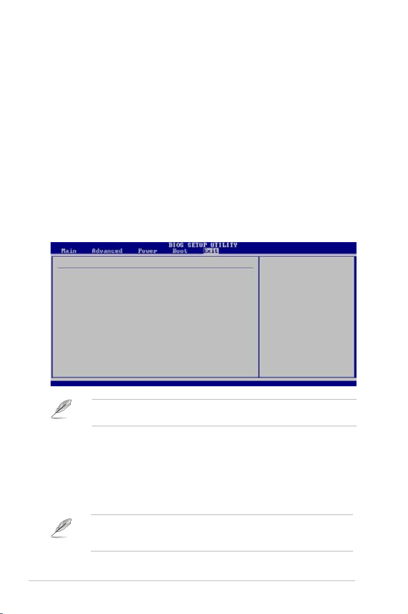
2-30 Chapter 2: BIOS Information
2.7 Exit menu
The Exit menu items allow you to load the optimal or failsafe default values for the
BIOS items, and save or discard your changes to the BIOS items.
Pressing <Esc> does not immediately exit this menu. Select one of the options
from this menu or <F10> from the legend bar to exit.
ExitOptions
Exit&SaveChanges
Exit&DiscardChanges
Discard Changes
Load Setup Defaults
Exitsystemsetup
after saving the
changes.
F10 key can be used
for this operation.
v02.54(C)Copyright1985-2003,AmericanMegatrends,Inc.
←→
Select Screen
↑↓
Select Item
Enter Go to Sub Screen
F1 General Help
F10 SaveandExit
ESC Exit
Exit & Save Changes
Once you are nished making your selections, choose this option from the Exit
menu to ensure the values you selected are saved to the CMOS RAM. The CMOS
RAM is sustained by an onboard backup battery and stays on even when the PC
is turned off. When you select this option, a conrmation window appears. Select
[OK] to save changes and exit.
If you attempt to exit the Setup program without saving your changes, the
program prompts you with a message asking if you want to save your changes
before exiting. Pressing <Enter> saves the changes while exiting.
To set a User Password:
1. Select the Change User Password item and press <Enter>.
2. On the password box that appears, type a password composed of at
least six letters and/or numbers, then press <Enter>.
3. Conrm the password when prompted.
Th e mes sag e “ Passwor d I nst alle d” app ears aft er you set you r p assword
successfully.
To change the user password, follow the same steps as in setting a user password.
Page 71

ASUS P5V-VM Ultra Motherboard 2-31
Exit & Discard Changes
Select this option only if you do not want to save the changes that you made to the
Setup program. If you made changes to elds other than system date, system time,
and password, the BIOS asks for a conrmation before exiting.
Discard Changes
This op ti on allows you to discard the selections you mad e and restore the
previously saved values. After selecting this option, a conrmation appears. Select
[OK] to discard any changes and load the previously saved values.
Load Setup Defaults
This option allows you to load the default values for each of the parameters on the
Setup menus. When you select this option, or if you press <F5>, a conrmation
window appears. Select [OK] to load the default values. Select Exit & Save
Changes or make other changes before saving the values to the non-volatile RAM.
Page 72

2-32 Chapter 2: BIOS Information
Page 73

Thi s cha p ter desc ribe s the con t ents
of the support CD that comes with the
motherboard package.
Chapter 3
Software Support
Page 74

3-34 Chapter 3: Software Support
If Autorun is NOT enabled in your computer, browse the contents of the support
CD to locate the file ASSETUP.EXE from the BIN folder. Double-click the
ASSETUP.EXE to run the CD.
Click an item to install
3.1 Installing an operating system
This motherboard supports Windows® 2000/XP operating systems (OS). Always
install the latest OS version and corresponding updates to maximize the features of
your hardware.
3.2 Support CD information
The support CD that came with the motherboard package contains the drivers,
software applications, and utilities that you can install to avail all motherboard
features.
3.2.1 Running the support CD
Place the support CD to the optical drive. The CD automatically displays the
Drivers menu if Autorun is enabled in your computer.
Motherboard settings and hardware options vary. Use the setup procedures
presented in this chapter for reference only. Refer to your OS documentation for
detailed information.
The contents of the support CD are subject to change at any time without notice.
Visit the ASUS website(www.asus.com) for updates.
Click an icon to
display support
CD/motherboard
information
Page 75

ASUS P5V-VM Ultra Motherboard 3-35
3.2.2 Drivers menu
The drivers menu shows the available device drivers if the system detects installed
devices. Install the necessary drivers to activate the devices.
VIA 4 in 1 Drivers
Install VIA 4 in 1 drivers.
VIA Onboard VGA Driver
Install VIA Onboard VGA driver.
Microsoft AZALIA Audio Hotx
Install Microsoft AZALIA Audio Hotx.
Realtek Audio Driver
Install Realtek Audio driver.
VIA Rhine Family Fast Ethernet Adapter Driver
Install VIA Rhine Family Fast Ethernet Adapter driver.
VIA RAID Driver
Install VIA RAID driver.
The scree n di splay and driv ers optio n ma y no t be the same for different
operating system versions.
3.2.3 Utilities menu
The Utilities menu shows the applications and other softwares that the motherboard
supports.
Page 76

3-36 Chapter 3: Software Support
ASUS PC Probe II
This smart utility monitors the fan speed, CPU temperature, and system voltages,
and alerts you of any detected problems. This utility helps you keep your computer
in healthy operating condition.
ASUS Update
The ASUS Update utility allows you to update the motherboard BIOS in Windows®
environment. This utility requires an Internet connection either through a network or
an Internet Service Provider (ISP).
ADOBE Acrobat Reader V7.0
The Adobe Acrobat® Reader V7.0 is for opening, viewing, and printing documents
in Portable Document Format (PDF).
Microsoft DirectX 9.0c Driver
The Microsoft DirectX® 9.0c is a multimedia technology that enhances computer
graphics and sounds. DirectX® improves the multimedia features of your computer
so you can enjoy watching TV and movies, capturing videos, or playing games in
your computer.
Page 77

ASUS P5V-VM Ultra Motherboard 3-37
3.2.4 Make disk menu
The Utilities menu shows you to make a RAID driver disk.
VIA RAID Driver
Allows you to create a VT8237A 32/64bit RAID driver disk.
3.2.5 Manuals menu
The Manuals menu contains a list of supplementary user manuals. Click an
item to open the folder of the user manual.
Most user manual les are in Portable Document Format (PDF). Install the Adobe
®
Acrobat® Reader from the Utilities menu before opening a user manual le.
Page 78

3-38 Chapter 3: Software Support
VIA8237 SATA Quick setup User’s Manual
Allows you to open the VIA8237 SATA quick setup user’s manual.
3.2.6 ASUS Contact information
Click the Contact tab to display the ASUS contact information. You can also nd
this information on the inside front cover of this user guide.