


Asus P5LD2-X/1333 User Manual

P5LD2-X/1333
Motherboard

E3519
Revised Edition V2
October 2007
Copyright © 2007 ASUSTeK COMPUTER INC. All Rights Reserved.
No part of this manual, including the products and software described in it, may be reproduced,
transmitted, transcribed, stored in a retrieval system, or translated into any language in any form or by any
means, except documentation kept by the purchaser for backup purposes, without the express written
permission of ASUSTeK COMPUTER INC. (“ASUS”).
Product warranty or service will not be extended if: (1) the product is repaired, modied or
altered, unless such repair, modication of alteration is authorized in writing by ASUS; or (2)
the serial number of the product is defaced or missing.
ASUS PROVIDES THIS MANUAL “AS IS” WITHOUT WARRANTY OF ANY KIND, EITHER
EXPRESS OR IMPLIED, INCLUDING BUT NOT LIMITED TO THE IMPLIED WARRANTIES
OR CONDITIONS OF MERCHANTABILITY OR FITNESS FOR A PARTICULAR PURPOSE.
IN NO EVENT SHALL ASUS, ITS DIRECTORS, OFFICERS, EMPLOYEES OR AGENTS BE
LIABLE FOR ANY INDIRECT, SPECIAL, INCIDENTAL, OR CONSEQUENTIAL DAMAGES
(INCLUDING DAMAGES FOR LOSS OF PROFITS, LOSS OF BUSINESS, LOSS OF USE
OR DATA, INTERRUPTION OF BUSINESS AND THE LIKE), EVEN IF ASUS HAS BEEN
ADVISED OF THE POSSIBILITY OF SUCH DAMAGES ARISING FROM ANY DEFECT OR
ERROR IN THIS MANUAL OR PRODUCT.
SPECIFICATIONS AND INFORMATION CONTAINED IN THIS MANUAL ARE FURNISHED
FOR INFORMATIONAL USE ONLY, AND ARE SUBJECT TO CHANGE AT ANY TIME
WITHOUT NOTICE, AND SHOULD NOT BE CONSTRUED AS A COMMITMENT BY
ASUS. ASUS ASSUMES NO RESPONSIBILITY OR LIABILITY FOR ANY ERRORS OR
INACCURACIES THAT MAY APPEAR IN THIS MANUAL, INCLUDING THE PRODUCTS
AND SOFTWARE DESCRIBED IN IT.
Products and corporate names appearing in this manual may or may not be registered
trademarks or copyrights of their respective companies, and are used only for identication or
explanation and to the owners’ benet, without intent to infringe.
ii

Contents
Notices ......................................................................................................... vi
Safety information
About this guide
P5LD2-X/1333 specications summary ..................................................... x
Chapter 1: Product introduction
1.1 Welcome! ...................................................................................... 1-1
1.2 Package contents
1.3 Special features
1.3.1 Product highlights ...........................................................
1.3.2 Innovative ASUS features ...............................................
Chapter 2: Hardware information
2.1 Before you proceed ..................................................................... 2-1
2.2 Motherboard overview
2.2.1 Placement direction ........................................................
2.2.2 Screw holes ....................................................................
2.2.3 Motherboard layout .........................................................
2.2.4 Layout contents ...............................................................
2.3 Central Processing Unit (CPU)
2.3.1 Installing the CPU ...........................................................
2.3.2 Installing the CPU heatsink and fan ................................
2.3.3 Uninstalling the CPU heatsink and fan ..........................
2.4 System memory
2.4.1 Overview .......................................................................
2.4.2 Memory congurations ..................................................
2.4.3 Installing a DIMM ..........................................................
2.4.4 Removing a DIMM ........................................................
2.5 Expansion slots
2.5.1 Installing an expansion card .........................................
2.5.2 Conguring an expansion card .....................................
2.5.3 Interrupt assignments ...................................................
2.5.4 PCI slots ........................................................................
2.5.5 PCI Express x16 slot .....................................................
2.5.6 PCI Express x1 slot .......................................................
2.6 Jumpers
..................................................................................... vii
....................................................................................... viii
......................................................................... 1-1
............................................................................ 1-2
................................................................. 2-2
................................................... 2-6
......................................................................... 2-13
.......................................................................... 2-18
...................................................................................... 2-21
1-2
1-4
2-2
2-2
2-3
2-4
2-6
2-9
2-11
2-13
2-13
2-17
2-17
2-18
2-18
2-19
2-20
2-20
2-20
iii

Contents
2.7 Connectors ................................................................................. 2-23
2.7.1 Rear panel connectors ..................................................
2.7.2 Internal connectors .......................................................
Chapter 3: Powering up
3.1 Starting up for the rst time ........................................................ 3-1
3.2 Powering off the computer
3.2.1 Using the OS shut down function ....................................
3.2.2 Using the dual function power switch ..............................
Chapter 4: BIOS setup
4.1 Managing and updating your BIOS ............................................ 4-1
4.1.1 Creating a bootable oppy disk .......................................
4.1.2 AFUDOS utility ................................................................
4.1.3 ASUS CrashFree BIOS 2 utility ......................................
4.1.4 ASUS EZ Flash utility ......................................................
4.1.5 ASUS Update utility ........................................................
4.2 BIOS setup program
4.2.1 BIOS menu screen ........................................................
4.2.2 Menu bar .......................................................................
4.2.3 Navigation keys .............................................................
4.2.4 Menu items ...................................................................
4.2.5 Sub-
4.2.6 Conguration elds .......................................................
4.2.7 Pop-up window .............................................................
4.2.8 Scroll bar .......................................................................
4.2.9 General help .................................................................
4.3 Main menu
4.3.1 System Time ................................................................
4.3.2 System Date .................................................................
4.3.3 Legacy Diskette A ........................................................
4.3.4 Primary, Third and Fourth IDE Master/Slave ................
4.3.5 IDE Conguration ..........................................................
4.3.6 System Information .......................................................
4.4 Advanced menu
4.4.1 USB Conguration ........................................................
menu items ............................................................ 4-13
.................................................................................. 4-14
......................................................................... 4-18
.......................................................... 3-2
.................................................................. 4-11
2-23
2-24
3-2
3-2
4-1
4-2
4-5
4-7
4-8
4-12
4-12
4-12
4-13
4-13
4-13
4-13
4-13
4-14
4-14
4-14
4-15
4-16
4-17
4-18
iv

Contents
4.4.2 CPU Conguration ........................................................ 4-20
4.4.3 Chipset ..........................................................................
4.4.4 Onboard Devices Conguration ....................................
4.4.5 PCI PnP ........................................................................
4.5 Power menu
4.5.1 Suspend Mode .............................................................
4.5.2 ACPI 2.0 Support .........................................................
4.5.3 ACPI APIC Support ......................................................
4.5.4 APM Conguration ........................................................
4.5.5 Hardware Monitor .........................................................
4.6 Boot menu
4.6.1 Boot Device Priority ......................................................
4.6.2 Boot Settings Conguration ..........................................
4.6.3 Security .........................................................................
4.7 Exit menu
Chapter 5: Software support
5.1 Installing an operating system ................................................... 5-1
5.2 Support CD information
5.2.1 Running the support CD .................................................
5.2.2 Drivers menu ...................................................................
5.2.3 Utilities menu ..................................................................
5.2.4 ASUS Contact information ..............................................
5.2.5 Other information ............................................................
5.3 ASUS MyLogo™
................................................................................ 4-27
.................................................................................. 4-31
.................................................................................... 4-36
.............................................................. 5-1
........................................................................... 5-6
4-21
4-23
4-25
4-27
4-27
4-27
4-28
4-30
4-31
4-32
4-33
5-1
5-2
5-3
5-4
5-4
Appendix: CPU features
A.1 Enhanced Intel SpeedStep® Technology (EIST) ........................A-1
A.1.1 System requirements ......................................................
A.1.2 Using the EIST ................................................................
®
A.2 Intel
Hyper-Threading Technology ...........................................A-2
Using the Hyper-Threading Technology ........................................A-2
A-1
A-1
v

Notices
Federal Communications Commission Statement
This device complies with Part 15 of the FCC Rules. Operation is subject to the
following two conditions:
•
This device may not cause harmful interference, and
•
This device must accept any interference received including interference that
may cause undesired operation.
This equipment has been tested and found to comply with the limits for a
Class B digital device, pursuant to Part 15 of the FCC Rules. These limits are
designed to provide reasonable protection against harmful interference in a
residential installation. This equipment generates, uses and can radiate radio
frequency energy and, if not installed and used in accordance with manufacturer’s
instructions, may cause harmful interference to radio communications. However,
there is no guarantee that interference will not occur in a particular installation. If
this equipment does cause harmful interference to radio or television reception,
which can be determined by turning the equipment off and on, the user is
encouraged to try to correct the interference by one or more of the following
measures:
•
Reorient or relocate the receiving antenna.
•
Increase the separation between the equipment and receiver.
•
Connect the equipment to an outlet on a circuit different from that to which the
receiver is connected.
•
Consult the dealer or an experienced radio/TV technician for help.
The use of shielded cables for connection of the monitor to the graphics card is
required to assure compliance with FCC regulations. Changes or modications
to this unit not expressly approved by the party responsible for compliance
could void the user’s authority to operate this equipment.
Canadian Department of Communications Statement
This digital apparatus does not exceed the Class B limits for radio noise emissions
from digital apparatus set out in the Radio Interference Regulations of the
Canadian Department of Communications.
This class B digital apparatus complies with Canadian
ICES-003.
vi

Safety information
Electrical safety
•
To prevent electrical shock hazard, disconnect the power cable from the
electrical outlet before relocating the system.
•
When adding or removing devices to or from the system, ensure that the
power cables for the devices are unplugged before the signal cables are
connected. If possible, disconnect all power cables from the existing system
before you add a device.
•
Before connecting or removing signal cables from the motherboard, ensure
that all power cables are unplugged.
•
Seek professional assistance before using an adpater or extension cord.
These devices could interrupt the grounding circuit.
•
Make sure that your power supply is set to the correct voltage in your area.
If you are not sure about the voltage of the electrical outlet you are using,
contact your local power company.
•
If the power supply is broken, do not try to x it by yourself. Contact a
qualied service technician or your retailer.
Operation safety
•
Before installing the motherboard and adding devices on it, carefully read all
the manuals that came with the package.
•
Before using the product, make sure all cables are correctly connected and the
power cables are not damaged. If you detect any damage, contact your dealer
immediately.
•
To avoid short circuits, keep paper clips, screws, and staples away from
connectors, slots, sockets and circuitry.
•
Avoid dust, humidity, and temperature extremes. Do not place the product in
any area where it may become wet.
•
Place the product on a stable surface.
•
If you encounter technical problems with the product, contact a qualied
service technician or your retailer.
The symbol of the crossed out wheeled bin indicates that the
product (electrical, electronic equipment, Mercury-containing button
cell battery) should not be placed in municipal waste. Check local
regulations for disposal of electronic products.
vii

About this guide
This user guide contains the information you need when installing and conguring
the motherboard.
How this guide is organized
This guide contains the following parts:
• Chapter 1: Product introduction
This chapter describes the features of the motherboard and the new
technology it supports.
• Chapter 2: Hardware information
This chapter lists the hardware setup procedures that you have to perform
when installing system components. It includes description of the switches,
jumpers, and connectors on the motherboard.
• Chapter 3: Powering up
This chapter describes the power up sequence, the vocal POST messages,
and ways of shutting down the system.
• Chapter 4: BIOS setup
This chapter tells how to change system settings through the BIOS Setup
menus. Detailed descriptions of the BIOS parameters are also provided.
• Chapter 5: Software support
This chapter describes the contents of the support CD that comes with the
motherboard package.
• Appendix: CPU features
The Appendix describes the CPU features that the motherboard supports.
Where to nd more information
Refer to the following sources for additional information and for product and
software updates.
1. ASUS websites
The ASUS website provides updated information on ASUS hardware and
software products. Refer to the ASUS contact information.
2. Optional documentation
Your product package may include optional documentation, such as warranty
yers, that may have been added by your dealer. These documents are not
part of the standard package.
viii

Conventions used in this guide
To make sure that you perform certain tasks properly, take note of the following
symbols used throughout this manual.
DANGER/WARNING: Information to prevent injury to yourself
when trying to complete a task.
CAUTION: Information to prevent damage to the components
when trying to complete a task.
IMPORTANT: Instructions that you MUST follow to complete a
task.
NOTE: Tips and additional information to help you complete a
task.
Typography
Bold text Indicates a menu or an item to select.
Italics
Used to emphasize a word or a phrase.
<Key> Keys enclosed in the less-than and greater-than sign
means that you must press the enclosed key.
Example: <Enter> means that you must press the
Enter or Return key.
<Key1>+<Key2>+<Key3> If you must press two or more keys simultaneously, the
key names are linked with a plus sign (+).
Example: <Ctrl>+<Alt>+<D>
Command Means that you must type the command exactly
as shown, then supply the required item or value
enclosed in brackets.
Example: At the DOS prompt, type the command line:
afudos /i[lename]
afudos /iP5LD2XOC.ROM
ix
P5LD2-X/1333 specications summary
CPU
Chipset
Front Side Bus
Memory
Expansion slots
Storage
Audio
USB
LAN
ASUS special features
BIOS features
Back Panel I/O Ports
LGA775 socket for Intel® Prescott/Smitheld/Cedarmill/
Conroe/Conroe L/Presler processors
Supports Intel® EIST/Hyper-Threading Technology
Northbridge: Intel® MCH 945GC
Southbridge: Intel® ICH7
1333(O.C)/1066/800/533 MHz
2 x 240-pin DIMM sockets support unbuffered non-ECC
DDR2 400/533/667 memory modules
Supports up to 2 GB system memory
1 x PCIe x16 slot for discrete graphic card
2 x PCIe x1 slots
3 x PCI slots
Intel® ICH7 South Bridge supports:
- 1 x Ultra DMA 100/66
- 4 x Serial ATA 3Gb/s devices
ALC662 High Denition Audio 6-channel CODEC
Supports S/PDIF out interface and Jack-detect
Supports up to 8 USB 2.0/USB 1.1 ports
PCIe 10/100Mb LAN
ASUS C.P.R. (CPU Parameter Recall)
ASUS CrashFree BIOS 2
ASUS MyLogo
ASUS EZ Flash
ASUS Q-fan
ASUS CPU Lock Free
ASUS CPU multiplier
4 Mb Flash ROM, AMI BIOS
Special H/W write production, PnP, DMI v2.0, WfM2.0
SM BIOS v2.4, ACPI v2.0
1 x Parallel port
1 x COM
1 x S/PDIF Out port
1 x PS/2 keyboard port
1 x PS/2 mouse port
1 x RJ45
4 x USB 2.0/1.1
6-channel Audio I/O
(continued on the next page)
x
P5LD2-X/1333 specications summary
Internal I/O connectors
Manageability
Support CD contents
Accessories
Form Factor
*Specications are subject to change without notice.
Azalia High Denition Analog Front Panel Audio connector
Chassis Intrusion
1 x 4-pin internal speaker connector
1 x 24-pin EPS12V power connector
1 x 4-pin ATX 12V power connector
2 x USB connectors for 4 additional USB 2.0 ports
1 x CD audio-in connector
CPU/Chassis fan connectors
WOL by PME, WOR by PME, WOR by Ring
Drivers
ASUS PC Probe II
ASUS LiveUpdate Utility
1 x SATA cable
1 x SATA power cable
1 x FDD cable
1 x UltraDMA 100/66 cable
1 x I/O Shield
User’s manual
ATX Form Factor, 12”x7.2” (30.5cm x 18.3cm)
xi

xii

This chapter describes the motherboard
features and the new technologies
it supports.
Product
1
introduction

Chapter summary
1
1.1 Welcome! ...................................................................................... 1-1
1.2 Package contents
1.3 Special features
......................................................................... 1-1
............................................................................ 1-2
ASUS P5LD2-X/1333
1.1 Welcome!
Thank you for buying an ASUS® P5LD2-X/1333 motherboard!
The motherboard delivers a host of new features and latest technologies, making it
another standout in the long line of ASUS quality motherboards!
Before you start installing the motherboard, and hardware devices on it, check the
items in your package with the list below.
1.2 Package contents
Check your motherboard package for the following items.
Motherboard ASUS P5LD2-X/1333 motherboard
Cables 1 x FDD cable
1 x SATA cable
1 x SATA power cable
1 x UltraDMA 100/66 cable
Accessories I/O shield
Application CDs ASUS motherboard support CD
Documentation User guide
If any of the above items is damaged or missing, contact your retailer.
ASUS P5LD2-X/1333 1-1
1.3 Special features
1.3.1 Product highlights
Latest processor technology
The motherboard comes with a 775-pin surface mount Land Grid Array (LGA)
socket designed for the Intel® Prescott, Intel® Smitheld, Intel® Cedarmill, Intel®
Conroe, Intel® Conroe L or Intel® Presler processor in the 775-land package. The
motherboard supports the processors with 1333 (O.C)/1066/800/533 MHz Front
Side Bus (FSB). The motherboard also supports the Intel® Hyper-Threading
Technology and Enhanced Intel® SpeedStep Technology (EIST). See pages 2-6,
A-1 and A-2 for details.
Intel® Core™2
This motherboard supports the latest Intel® Core™2 processor in the LGA775
package. With the new Intel® Core™ microarchitecture technology and 1333
(O.C)/1066/800/533 MHz FSB, Intel® Core™2 processor is one of the most
powerful and energy efcient CPU in the world.
Intel® 65nm Dual-Core CPU support
This motherboard support Intel® Prescott, Intel® Smitheld, Intel® Cedarmill, Intel®
Conroe, Intel® Conroe L or Intel® Presler processors built on the 65-nanometer
(nm) process technology with copper interconnect. Dual-core processors contain
two physical CPU cores with dedicated L2 caches to meet demands for more
powerful processing. The 65nm process of Intel® is the most advanced chip
manufacturing technology, delivering breakthrough performance, enhanced media
experience, and low power consumption. Intel® 65nm dual-core processors utilize
the latest package technologies for a thinner, lighter design without compromising
performance.
64 - bit C PU su ppo rt
64-bit computing, the next generation technology to replace current 32-bit
architecture, delivers advanced system performance, faster memory access and
increased productivity. This motherboard provides excellent compatibility and
exibility by supporting either 64-bit or 32-bit architecture.
1-2 Chapter 1: Product introduction
DDR2 memory support
The motherboard supports DDR2 memory that features data transfer rates of
667/533/400 MHz to meet the higher bandwidth requirements of the latest
3D graphics, multimedia, and Internet applications. The dual-channel DDR2
architecture doubles the bandwidth of your system memory to boost system
performance, eliminating bottlenecks with peak bandwidths of up to10.6 GB/s. See
page 2-13 for details.
High Denition Audio
The onboard 6-channel ALC662 High Denition audio CODEC enables high-quality
audio which automatically detects peripherals are plugged into the audio I/O jacks.
ALC662 also supports Windows® Vista Premium. See pages 2-23 for details.
Serial ATA 3.0 Gb/s technology
This motherboard supports the next-generation hard drives based on the Serial
ATA (SATA) 3Gb/s storage specication, delivering enhanced scalability and
doubling the bus bandwidth for high-speed data retrieval and saves. Easily backup
photos, videos and other entertainment contents to external devices. See page
2-25 for details.
S/PDIF digital sound ready
The motherboard supports the S/PDIF technology through the S/PDIF interfaces
on the rear panel. The S/PDIF technology turns your computer into a high-end
entertainment system with digital connectivity to powerful audio and speaker
systems. See page 2-24 for details.
PCI Express™ interface
The motherboard fully supports PCI Express, the latest I/O interconnect technology
that speeds up the PCI bus. PCI Express features point-to-point serial
interconnections between devices and allows higher clockspeeds by carrying data
in packets. This high speed interface is software compatible with existing PCI
specications. See page 2-20 for details.
US B 2. 0 tec hn olo gy
The motherboard implements the Universal Serial Bus (USB) 2.0 specication,
dramatically increasing the connection speed from the 12 Mbps bandwidth on USB
1.1 to a fast 480 Mbps on USB 2.0. USB 2.0 is backward compatible with USB 1.1.
See pages 2-24 and 2-27 for details.
ASUS P5LD2-X/1333 1-3
Green ASUS
The motherboard and its packaging comply with the European Union’s Restriction
on the use of Hazardous Substances (RoHS). This is in line with the ASUS
vision of creating environment-friendly and recyclable products and packaging to
safeguard consumers’ health while minimizing the impact on the environment.
1.3.2 Innovative ASUS features
ASUS CrashFree BIOS 2
This feature allows you to restore the original BIOS data from the support CD in
case when the BIOS codes and data are corrupted. This protection eliminates the
need to buy a replacement ROM chip. See page 4-5 for details.
ASUS Q-Fan technology
The ASUS Q-Fan technology smartly adjusts the fan speeds according to the
system loading to ensure quiet, cool, and efcient operation. See page 4-30 for
details.
ASUS EZ Flash
With the ASUS EZ Flash, you can easily update the system BIOS even before
loading the operating system. No need to use a DOS-based utility or boot from a
oppy disk. See page 4-7 for details.
C.P.R. (CPU Parameter Recall)
The C.P.R. feature of the motherboard BIOS allows automatic re-setting to the
BIOS default settings in case the system hangs due to overclocking. When the
system hangs due to overclocking, C.P.R. eliminates the need to open the system
chassis and clear the RTC data. Simply shut down and reboot the system, and the
BIOS automatically restores the CPU default setting for each parameter.
ASUS CPU Lock Free
This feature allows you to adjust the CPU multiplier to 14x. Setting the appropriate
BIOS setting automatically reduces the CPU multiplier value for more exibility
when increasing external FSB.
1-4 Chapter 1: Product introduction

AS U S M yL ogo ™
The new feature present in the motherboard allows you to personalize and add
style to your system with customizable boot logos. See page 5-6 for details.
ASUS P5LD2-X/1333 1-5

1-6 Chapter 1: Product introduction

This chapter lists the hardware setup
procedures that you have to perform
when installing system components. It
includes description of the jumpers and
connectors on the motherboard.
information
Hardware
2

Chapter summary
2
2.1 Before you proceed ..................................................................... 2-1
2.2 Motherboard overview
2.3 Central Processing Unit (CPU)
2.4 System memory
2.5 Expansion slots
2.6 Jumpers
2.7 Connectors
...................................................................................... 2-21
................................................................................. 2-23
................................................................. 2-2
................................................... 2-6
......................................................................... 2-13
.......................................................................... 2-18
ASUS P5LD2-X/1333
2.1 Before you proceed
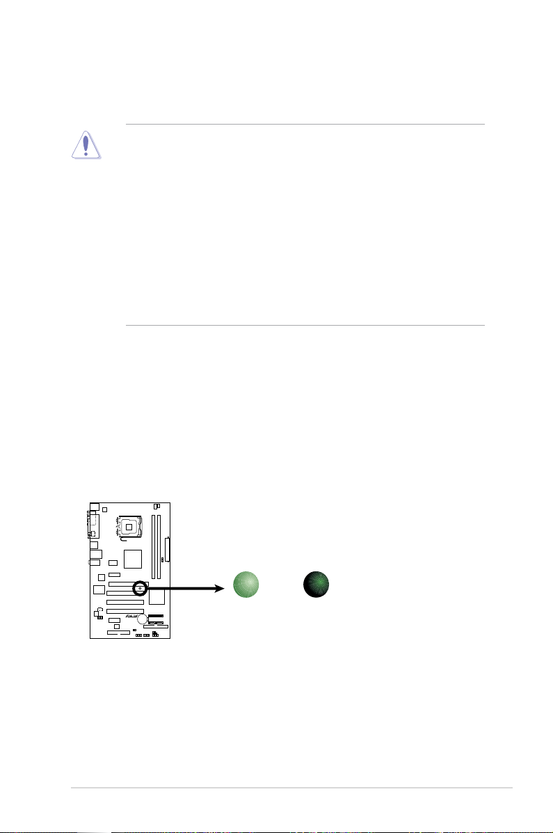
P5LD2-X/1333 Onboard LED
SB_PWR
ON
Standby
Power
OFF
Powered
Off
P5LD2-X/1333
Take note of the following precautions before you install motherboard components
or change any motherboard settings.
• Unplug the power cord from the wall socket before touching any
component.
• Use a grounded wrist strap or touch a safely grounded object or to
a metal object, such as the power supply case, before handling
components to avoid damaging them due to static electricity.
• Hold components by the edges to avoid touching the ICs on them.
• Whenever you uninstall any component, place it on a grounded
antistatic pad or in the bag that came with the component.
• Before you install or remove any component, ensure
that the ATX power supply is switched off or the power cord is detached
from the power supply. Failure to do so may cause severe damage to the
motherboard, peripherals, and/or components.
Onboard LED
The motherboard comes with a standby power LED. The green LED lights up
to indicate that the system is ON, in sleep mode, or in soft-off mode. This is a
reminder that you should shut down the system and unplug the power cable before
removing or plugging in any motherboard component. The illustration below shows
the location of the onboard LED.
ASUS P5LD2-X/1333 2-1
P5LD2-X/1333
2.2 Motherboard overview
Before you install the motherboard, study the conguration of your chassis to
ensure that the motherboard ts into it.
Make sure to unplug the power cord before installing or removing the
motherboard. Failure to do so can cause you physical injury and damage
motherboard components.
2.2.1 Placement direction
When installing the motherboard, make sure that you place it into the chassis in
the correct orientation. The edge with external ports goes to the rear part of the
chassis as indicated in the image below.
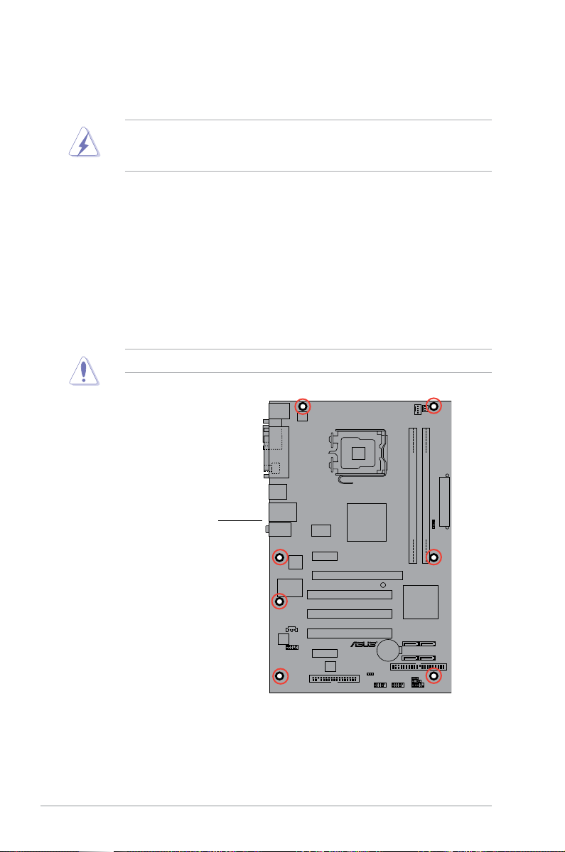
2.2.2 Screw holes
Place seven (7) screws into the holes indicated by circles to secure the
motherboard to the chassis.
Do not overtighten the screws! Doing so can damage the motherboard.
Place this side towards
the rear of the chassis
2-2 Chapter 2: Hardware information
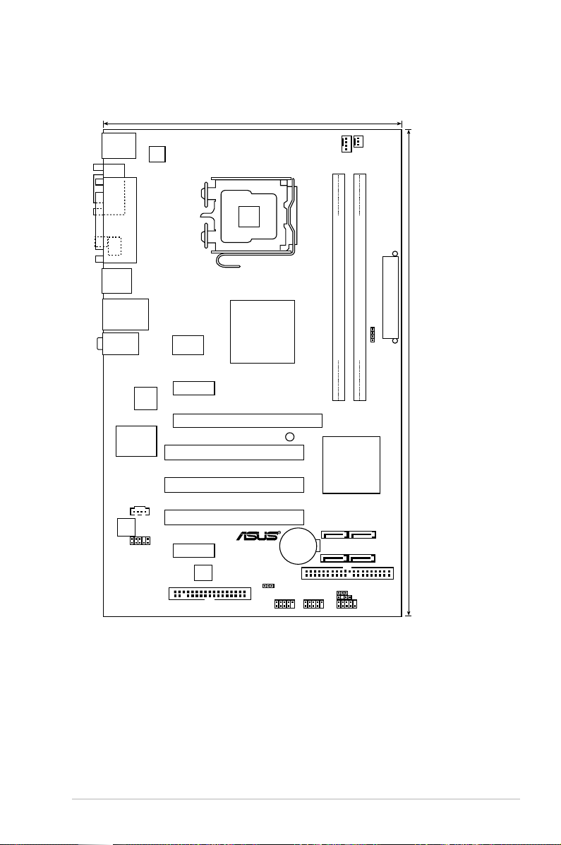
2.2.3 Motherboard layout
18.3cm (7.2in)
30.5cm (12in)
P5LD2-X/1333
LGA775
EATXPWR
SATA1
SATA3
SATA2
SATA4
Intel ICH7
Intel 945GC
PCI1
PRI_IDE
PCIEX1_1
PCI2
PCI3
PCIEX1_2
PCIEX16
AAFP
4Mb
BIOS
CR2032 3V
Lithium Cell
CMOS Power
AUDIO
LAN_USB12
USB34
e
PS/2KBMS
T: Mouse
B: K yboard
SPDIF_O1
PARALLE PORT
COM1
CPU_FAN
CHA_FAN
DDR2 DIMM_A1 (64 bit,240-pin module)
DDR2 DIMM_B1 (64 bit,240-pin module)
FLOPPY
USB56 USB78 F_PANEL
CHASSIS
CLRTC
PS2_USBPW
CD
ALC662
Super I/O
SB_PWR
Attansic
L2
RTM876-660-LF
ATX12V
SPEAKER
ASUS P5LD2-X/1333 2-3
2.2.4 Layout contents
Slots Page
1. PCIe x16 2-20
2. PCIe x 1 2-20
3. PCI 2-20
Jumpers Page
1. Clear RTC RAM (3-pin CLRTC) 2-21
2. USB Device wake-up (3-pin PS2_USBPWR) 2-22
Rear panel connectors Page
1. PS/2 mouse port (green) 2-23
2. Parallel port 2-23
3. LAN (RJ-45) port 2-23
4. Line In port (light blue) 2-23
5. Line Out port (green) 2-23
6. Microphone port (pink) 2-23
7. USB 2.0 ports 1 and 2 2-24
8. USB 2.0 ports 3 and 4 2-24
9. Coaxial S/PDIF Out port 2-24
10. Serial port (COM1) 2-24
11. PS/2 keyboard port (purple) 2-24
2-4 Chapter 2: Hardware information
Internal connectors Page
1. Floppy disk drive connector (34-1 pin FLOPPY) 2-24
2. ICH7 Primary IDE connector (40-1 pin PRI_IDE) 2-25
3. Serial ATA connectors (7-pin SATA1 [red], SATA2 [red], 2-25
SATA3 [black], SATA4 [black])
4. Optical drive audio connector (4-pin CD) 2-26
5. Front panel audio connector (10-1 pin AAFP) 2-27
6. USB connectors (10-1 pin USB56, USB78) 2-27
7. CPU and Chassis Fan connectors (4-pin CPU_FAN, 2-28
3-pin CHA_FAN)
8. Chassis intrusion connector (4-1 pin CHASSIS) 2-28
9. ATX power connectors (24-pin EATXPWR, 4-pin ATX12V) 2-29
10. Speaker connector (4-pin SPEAKER) 2-29
11. System panel connector (10-1 pin F_PANEL) 2-30
System power LED (2-pin PLED)
Hard disk drive activity LED (2-pin IDE_LED)
ATX power button/soft-off button (2-pin PWRBTN)
Reset button (2-pin RESET)
ASUS P5LD2-X/1333 2-5
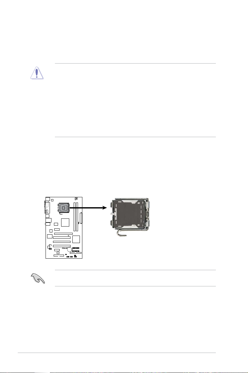
2.3 Central Processing Unit (CPU)
P5LD2-X/1333
CPU Socket 775
P5LD2-X/1333
The motherboard comes with a surface mount LGA775 socket designed for the
Intel® Prescott/Smitheld/Cedarmill/ Conroe/Conroe L/Presler processor in the
775-land package
•
Upon purchase of the motherboard, make sure that the PnP cap is on
the socket and the socket contacts are not bent. Contact your retailer
immediately if the PnP cap is missing, or if you see any damage to the PnP
cap/socket contacts/motherboard components. ASUS will shoulder the cost
of repair only if the damage is shipment/transit-related.
•
Keep the cap after installing the motherboard. ASUS will process Return
Merchandise Authorization (RMA) requests only if the motherboard comes
with the cap on the LGA775 socket.
• The product warranty does not cover damage to the socket contacts
resulting from incorrect CPU installation/removal, or misplacement/loss/
incorrect removal of the PnP cap.
2.3.1 Installing the CPU
To install a CPU:
1. Locate the CPU socket on the motherboard.
Before installing the CPU, make sure that the cam box is facing towards you
and the load lever is on your left.
2-6 Chapter 2: Hardware information
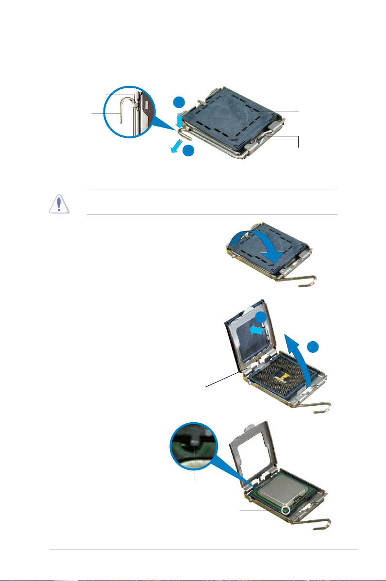
2. Press the load lever with your thumb (A), then move it to the left (B) until it is
released from the retention tab.
Retention tab
A
Load lever
B
To prevent damage to the socket pins, do not remove the PnP cap unless you
are installing a CPU.
3. Lift the load lever in the direction of
the arrow to a 135º angle.
4. Lift the load plate with your thumb
and forenger to a 100º angle (A),
then push the PnP cap from the load
plate window to remove (B).
PnP cap
This side of the socket
box should face you.
B
A
Load plate
5. Position the CPU over
the socket, making sure
that the gold triangle is
on the bottom-left corner
of the socket. The socket
alignment key should t
Alignment key
into the CPU notch.
Gold triangle mark
ASUS P5LD2-X/1333 2-7
The CPU ts in only one correct orientation. DO NOT force the CPU into the
socket to prevent bending the connectors on the socket and damaging the CPU!
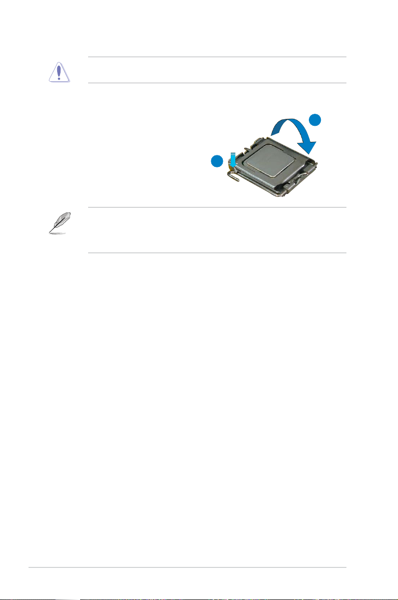
6. Close the load plate (A), then
push the load lever (B) until it
snaps into the retention tab.
The motherboard supports Intel® Prescott/Smitheld/Cedarmill/ Conroe/Conroe
L/Presler LGA775 processors with the Intel® Enhanced Intel SpeedStep®
Technology (EIST) and Hyper-Threading Technology. Refer to the Appendix for
more information on these CPU features.
A
B
2-8 Chapter 2: Hardware information
 Loading...