

Page 1

Service Source
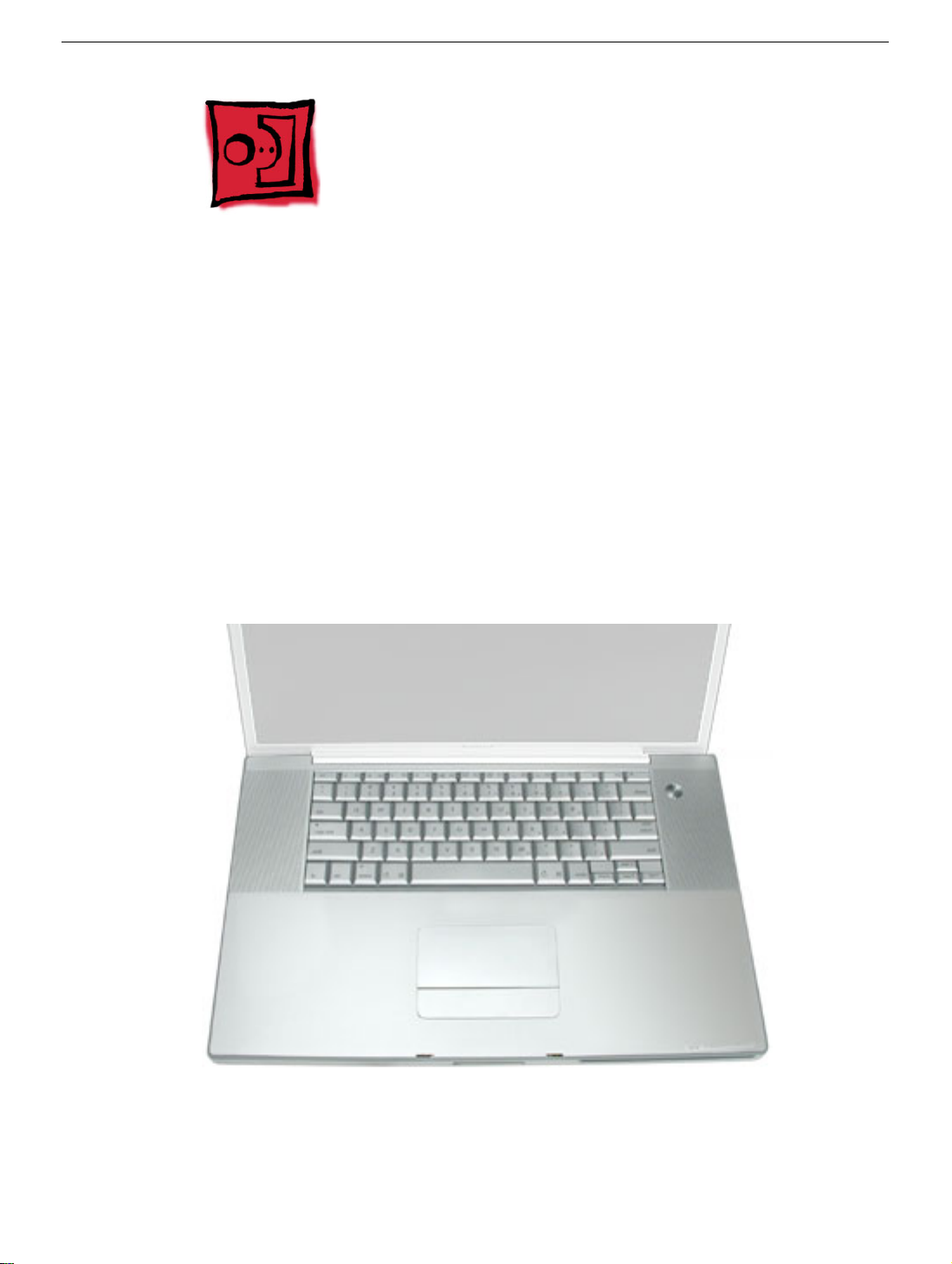
PowerBook G4 (17-inch)
5 December 2003
© 2003 Apple Computer, Inc. All rights reserved.
Page 2

Service Source
Take Apart
PowerBook G4 (17-inch)
© 2003 Apple Computer, Inc. All rights reserved.
Page 3
General Information
Overview
Some key features that distinguish this computer from earlier PowerBook models include:
• 17-inch TFT widescreen display in aluminum alloy enclosure
• Built-in Bluetooth
• Built-in AirPort Extreme card
• Added FireWire 800 port
• Uses double-data rate (DDR) memory
• Fiber optic backlit keyboard with ambient light sensor
New Procedures
If you are familiar with taking apart notebook computers, you will notice some differences
with this model:
• The keyboard is secured with screws accessible from under the top case.
• Memory cards are easily accessible from the bottom of the computer.
• The AirPort Extreme card is not user replaceable.
• The quantity and types of screws differ from earlier models.
PowerBook G4 (17-inch) Take Apart -
1
Page 4

Important Notes
• Memory from previous PowerBook models is not compatible with this computer. Do
not use older SDRAM DIMMs or SDIMMs even if they fit into the slot.
• The Bluetooth module is different from the PowerBook G4 (12-inch).
• The AirPort Extreme card assembly has a flex cable glued to the card, making it
unique and specific to this computer.
Tools
The following tools are recommended for the take apart procedures.
• ESD wrist strap and mat
• Soft cloth
• #00 Phillips screwdriver (magnetized)
• #0 Phillips screwdriver (magnetized)
• #1 Phillips screwdriver (magnetized)
• 4 mm socket wrench
• Needlenose pliers
• Torx T6 screwdriver
• Torx T8 screwdriver
• Black stick (nylon probe tool 922-5065) (or other nonconductive nylon or plastic flatblade tool)
• Razor knife with straight edge blade
• 1600 watt hair dryer (for logic board replacement)
• Multi-compartment screw tray (such as a plastic ice cube tray)
• Kapton® tape
• Voltmeter (for troubleshooting)
• Small low-power magnet (for troubleshooting)
• Apple Pro keyboard and mouse (for troubleshooting)
2 -
PowerBook G4 (17-inch) Take Apart
Page 5
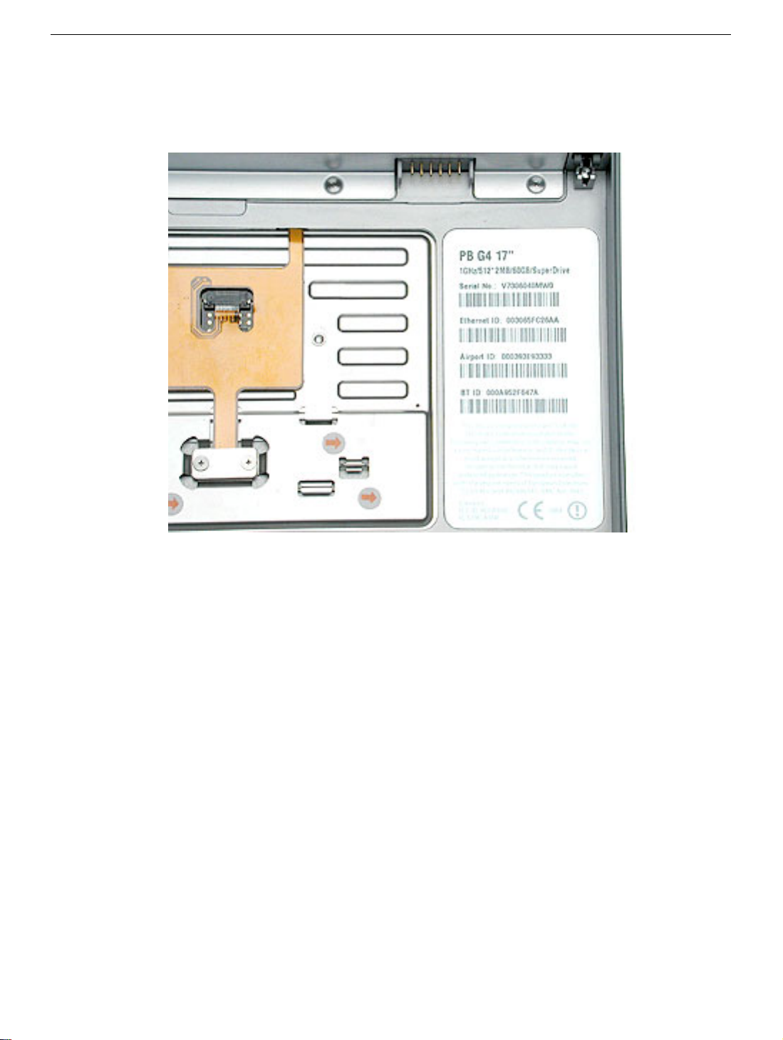
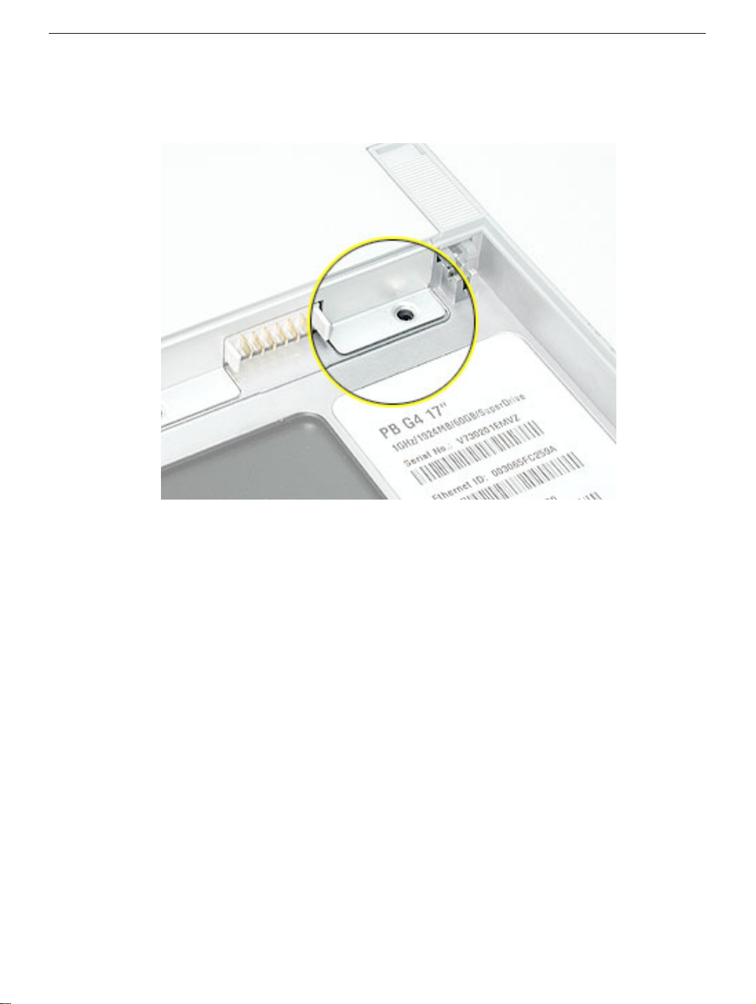
Serial Number Location
The serial number is located in the battery bay.
PowerBook G4 (17-inch) Take Apart -
3
Page 6
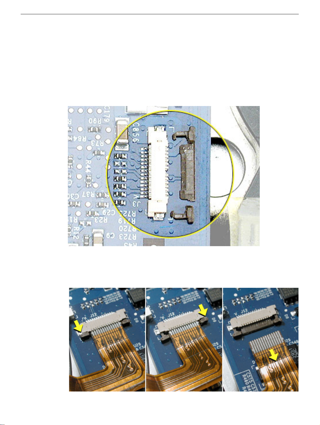
Zero Insertion Force Connectors
Zero insertion force (ZIF) connectors are used in several locations in the computer.
Important:
separate from the connector. When releasing a bar, use extreme care and a restrained
light pressure to move the bar only slightly.
Warning: If a locking bar breaks, you will need to replace the board.
The locking bar on the ZIF connector is extremely fragile and is not intended to
To release the flex cable
Use a flat-blade tool to move the bar on both sides.
4 -
PowerBook G4 (17-inch) Take Apart
Page 7
To connect a flex cable
Make sure the locking bar is released, then slide the end of the flex cable all the way into
the connector. Hold the cable in place, then slide the locking bar into the connector on
both sides to secure.
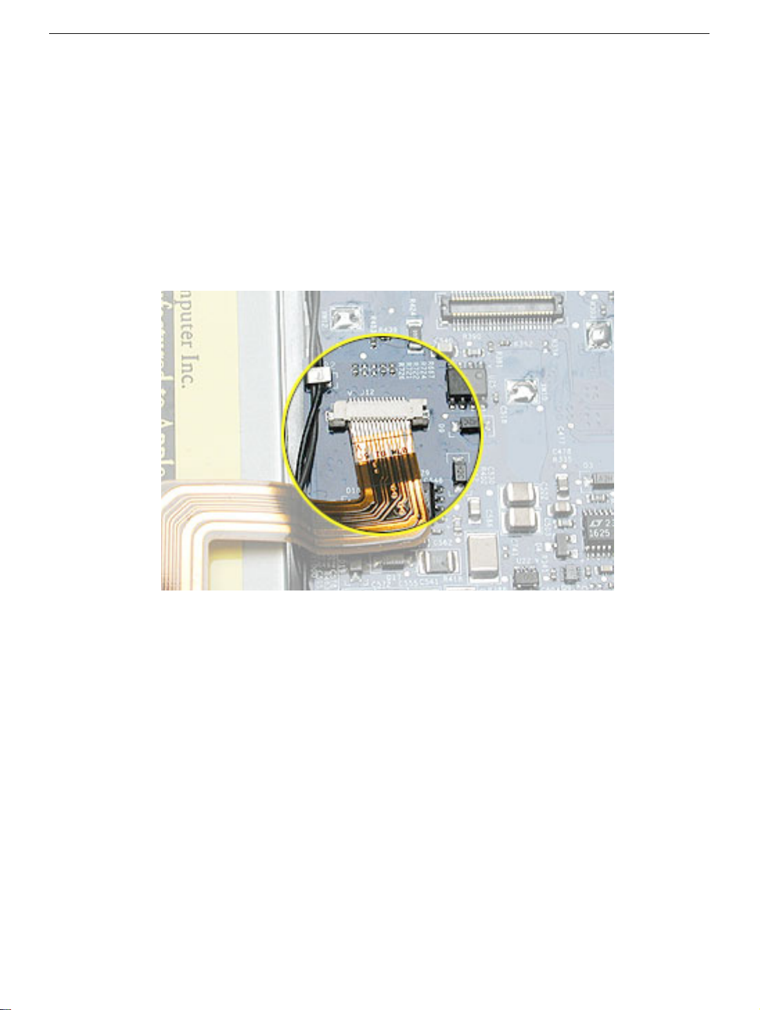
Important:
the metal edge on the cable as a guide to ensure the cable is straight.
Warning: If the flex cable is inserted crooked, some signals may not be connected
or signals may short together (a bad connection is shown below.)
Verify that the cable is straight. Use either the alignment mark, if present, or
Note:
If a cable is not securing properly, verify that it is inserted on the correct side of the
locking bar.
PowerBook G4 (17-inch) Take Apart -
5
Page 8
Feet
Tools
This procedure requires the following tools:
• Foot kit
• Tweezers or needlenose pliers
• Soft cloth
Preliminary Step
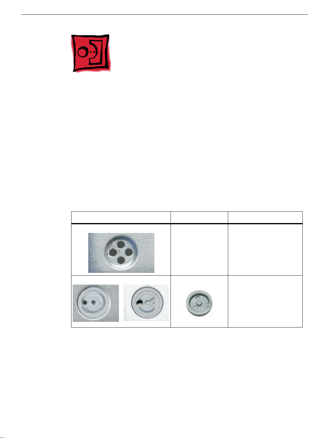
Before you begin, check the foot location that needs replacement on the bottom case, and
compare it with the images in this table. Make sure the foot you want to replace has an
intact plug on the bottom case.
Plug Area on Bottom Case Matching Foot Action
Missing plug Not available for
replacement
Case plug intact (either one) Replacement foot Continue with the
Replace the bottom
case, or send the
computer to the Apple
Repair Center for
repair.
procedure, matching
the replacement foot to
either plug on the
bottom case.
6 -
PowerBook G4 (17-inch) Take Apart
Feet
Page 9
Procedure
Warning:
glue. In the event of contact, review the safety instructions at the end of this section. For
additional information, refer to the glue manufacturer:
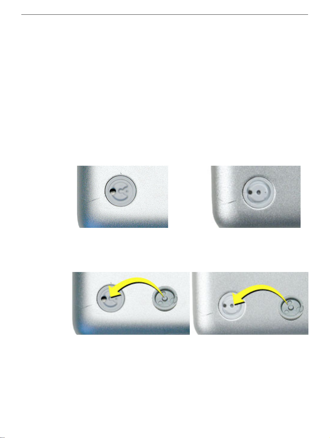
1. Place the computer upside down on a clean, lint-free cloth or other nonabrasive
2. Make sure the plug area on the bottom case is clean. If any portion of the soft rubber
The glue used in this procedure can bond instantly to skin. Do not touch the
Elmer's Products, Inc.
Columbus, OH. 43215-3799
www.krazyglue.com
surface.
foot remains, remove it so that only the hard plastic plug is visible (as shown with both
types of plugs below).
Important:
foot, make sure the raised bump on the textured plane of the rubber foot fits into the
center hole in the plug. This ensures a balanced and level fitting.
Notice the recessed hole in the center of the plug. When positioning the
Feet
PowerBook G4 (17-inch) Take Apart -
7
Page 10
3.
Warning:
touch the glue at any time. Before opening the glue, review the safety instructions at
the end of this section.
GLUE IS AN EYE AND SKIN IRRITANT. BONDS SKIN INSTANTLY. Do not
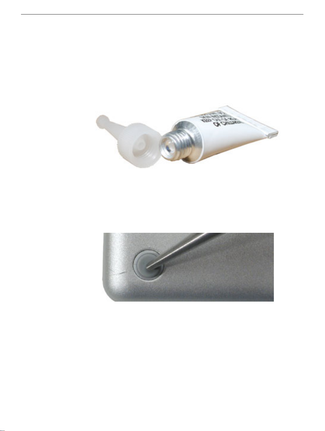
Important:
seal until you are ready to use the glue. To break the seal, hold the tube upright and
away from you. Place the hollow nozzle cap on the tube and tighten it all the way
down. The tube is then ready to dispense the glue through the nozzle cap.
4. Apply one drop of glue to the plug on the bottom case. Do not spread the glue.
5. Using tweezers or needlenose pliers, carefully position the new foot so it is centered
over the plug, and its integral bumps fit into the compatible holes in the plug.
6. Using the end of the tweezers or pliers—not your finger—lightly press and hold the
foot in place for 30 seconds.
The glue tube included in the kit is sealed until first use. Do not break the
7. Before turning over the computer, allow the glue to set for at least 15 minutes.
8. Discard the tube of glue.
SAFETY INSTRUCTIONS:
INSTANTLY. Contains ethyl cyanoacrylate. Avoid contact with skin and eyes. If eye or
mouth contact occurs, hold eyelid or mouth open and rinse thoroughly but gently with
water only for 15 minutes and GET MEDICAL ATTENTION. Liquid glue will sting eye
temporarily. Solidified glue may irritate eye like a grain of sand and should be treated by an
eye doctor. If skin bonding occurs, soak in acetone-based nail polish remover or warm
soapy water and carefully peel or roll skin apart (do not pull). Contact through clothing may
cause skin burn. If spilled on clothing, flush with cold water. Avoid prolonged breathing of
vapors. Use with adequate ventilation. KEEP OUT OF REACH OF CHILDREN.
8 -
PowerBook G4 (17-inch) Take Apart
GLUE IS AN EYE AND SKIN IRRITANT. BONDS SKIN
Feet
Page 11
Battery
Tools
This procedure requires the following tools:
• Soft cloth
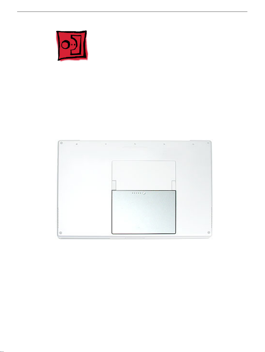
Part Location
Battery
Preliminary Steps
Warning: Always shut down the computer before opening it to avoid damaging its
internal components or causing injury. After you shut down the computer, the
internal components can be very hot. Let the computer cool down before
continuing.
PowerBook G4 (17-inch) Take Apart -
9
Page 12
Procedure
Warning: If the computer has been recently operating, allow it to cool down before
performing this procedure.
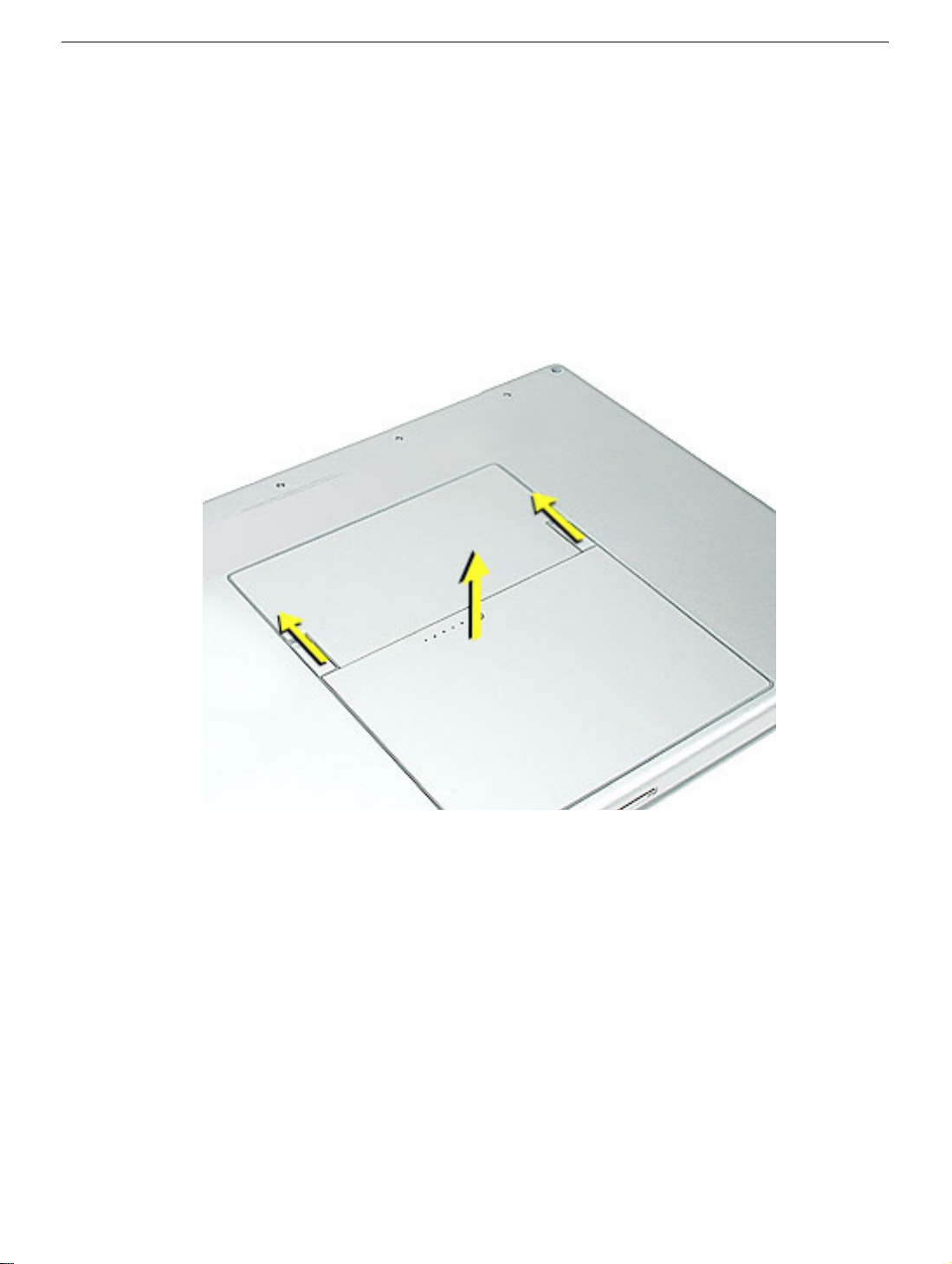
1. Shut down the computer.
2. Disconnect the power cord and any other cables connected to the computer.
3. Place the computer face down on a soft cloth.
4. Slide both battery latches away and lift the battery out of the battery bay.
10 -
PowerBook G4 (17-inch) Take Apart
Battery
Page 13
Memory Door and Memory Cards
Tools
This procedure requires the following tools:
• Soft cloth
• #0 Phillips screwdriver
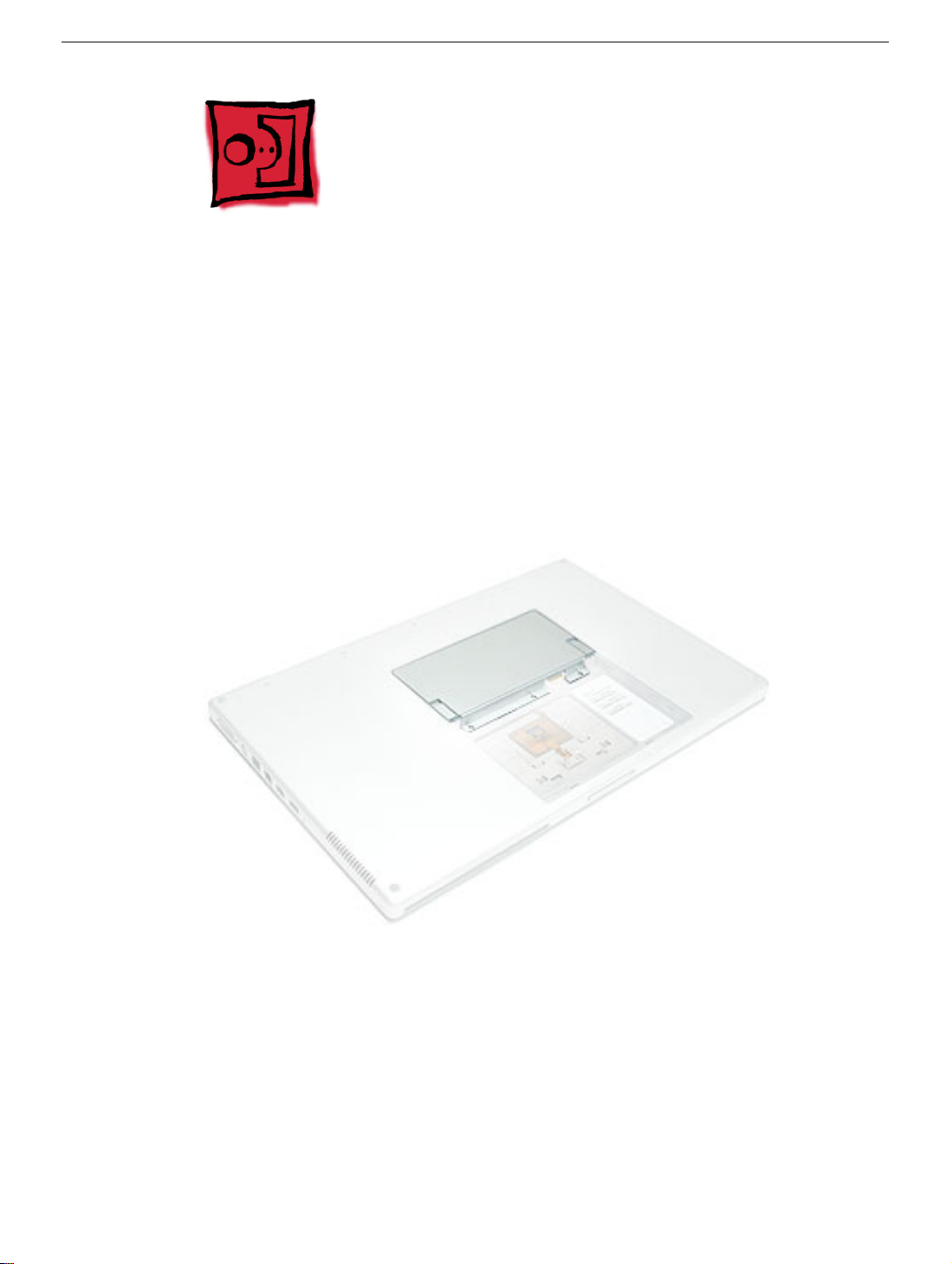
Part Location
Preliminary Steps
Before you begin, remove the battery.
Memory Door and Memory Cards
PowerBook G4 (17-inch) Take Apart -
11
Page 14
Procedure
Warning: If the computer has been recently operating, allow it to cool down before
performing this procedure.
1. Place the computer face down on a soft cloth.
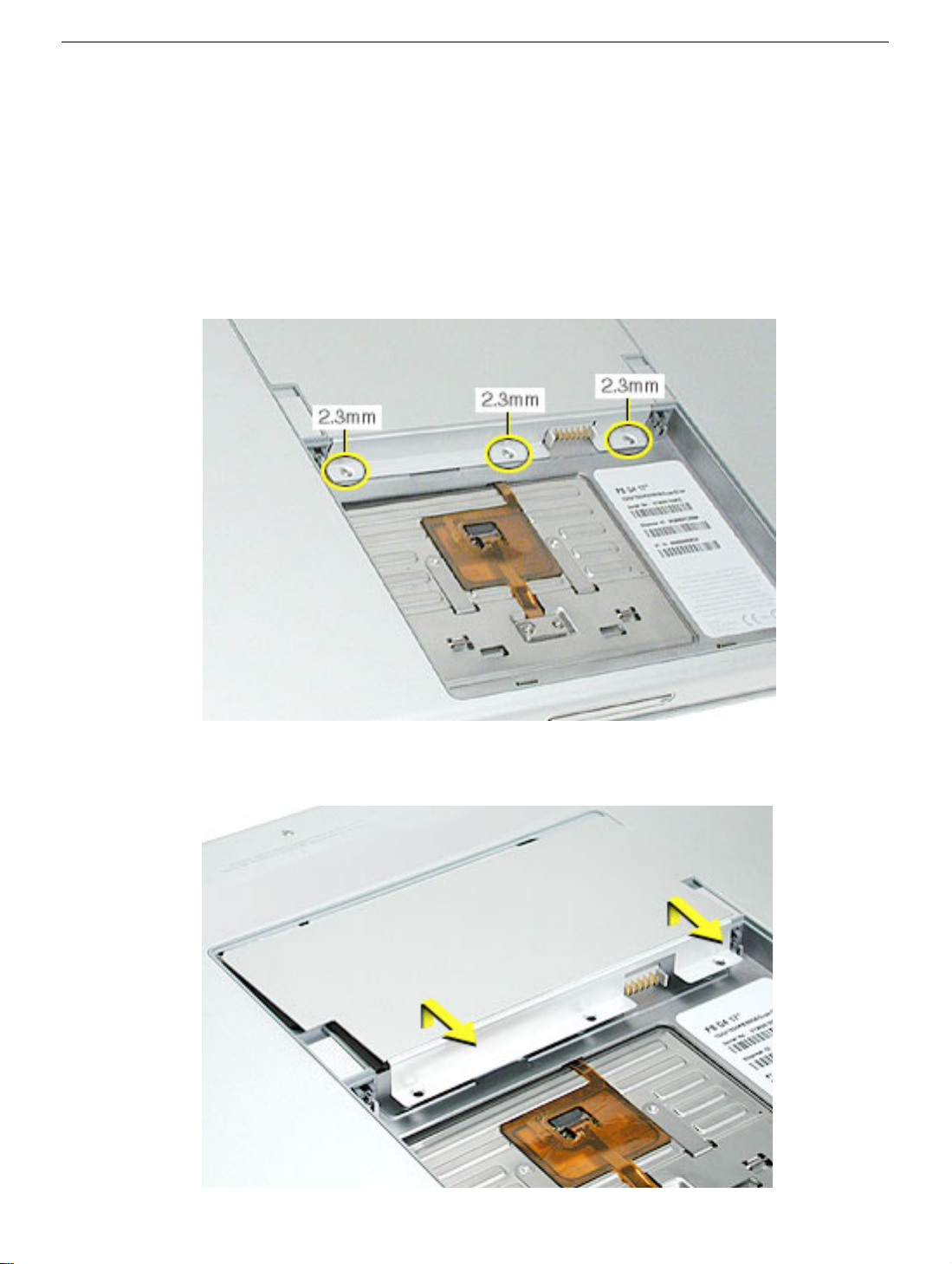
2. Remove the three screws from the memory door.
Note:
Check for lost screws caught by magnets inside the front edge of the battery well.
3. Lift the memory door up slightly and slide it straight back to remove.
12 -
PowerBook G4 (17-inch) Take Apart
Memory Door and Memory Cards
Page 15
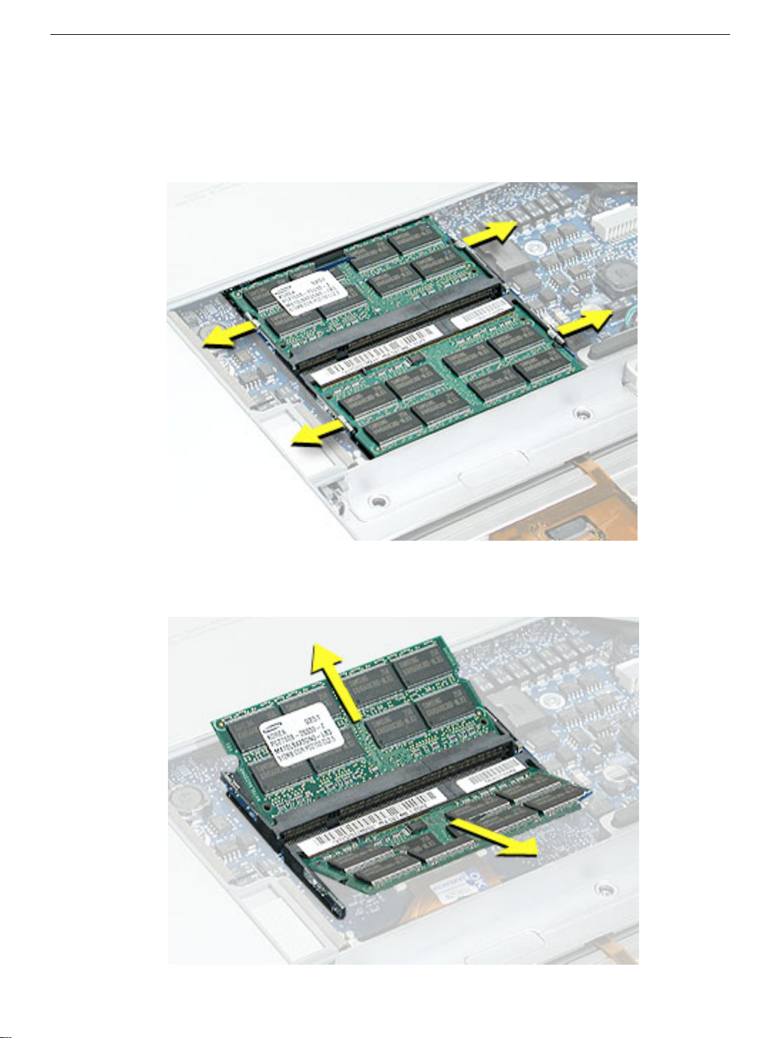
Note:
If only one memory card is installed, it’s factory installed in the top memory slot
(nearest to outside edge of the computer).
4. To remove either memory card, first release it by spreading apart the tabs in the
memory slot from the notches in the card until the card pops up slightly.
5. Pull the card straight out of the memory slot.
Memory Door and Memory Cards
PowerBook G4 (17-inch) Take Apart -
13
Page 16
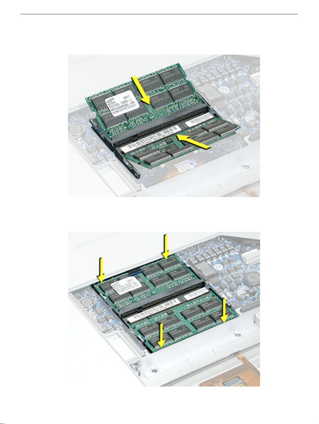
6. Align the notch in the board with the tab in the slot and insert the replacement memory
cards at a 30-degree angle, pushing the card firmly until fully seated.
7. Check that the notches in the card clear the tabs as you press down on the sides of
the card to lock it into place.
14 -
PowerBook G4 (17-inch) Take Apart
Memory Door and Memory Cards
Page 17
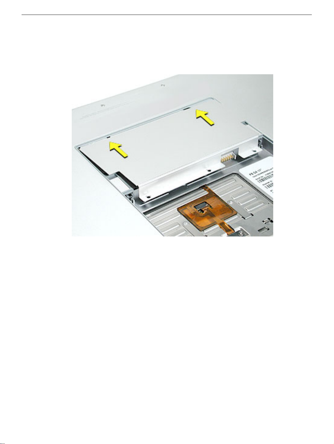
8. To reinstall the memory door, hold it at a low angle to the battery bay and slide it in
under the back edge, then lay it flat. If the door springs up and does not lay flat without
tension, remove it and reinstall at a lower angle.
Memory Door and Memory Cards
PowerBook G4 (17-inch) Take Apart -
15
Page 18
9. Install the memory door screws.
Note:
Before securing, check that the door edge rests flush and inside the ridge.
10. Replace the battery.
11. Use Apple System Profiler to verify that the memory is recognized. (Choose the menu
bar Apple logo (
open the Memory Overview.)
) > About This Mac, click More Info..., select the System Profile tab,
16 -
PowerBook G4 (17-inch) Take Apart
Memory Door and Memory Cards
Page 19
Top Case
Tools
This procedure requires the following tools:
• #0 Phillips screwdriver (magnetized)
• #1 Phillips screwdriver (magnetized)
• Torx T8 screwdriver (magnetized)
• Kapton tape (922-1731)
• Black stick (or other nonconductive nylon or plastic flat-blade tool)
• Soft cloth
• Multi-compartment screw tray (21 screws to remove the top case)
Part Location
Top Case
PowerBook G4 (17-inch) Take Apart -
17
Page 20
Preliminary Steps
Before you begin, remove the following:
• Battery
• Memory door
• Lower memory card (nearest to battery bay), if present
Procedure
Note:
This procedure removes the top case and keyboard assembly. The keyboard cannot
be removed until the top case is removed.
1. Place the computer face down on a soft cloth.
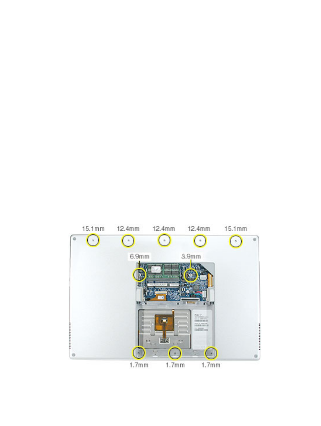
2. Remove the three screws inside the battery bay.
Note:
These screws are shorter than on the memory door. Use care not to lose the
screws into holes along the battery bay.
Note:
Check for lost screws caught by magnets inside the front edge of the battery well.
3. Remove the five screws along the back edge (the two outside screws are longer and
have “shoulders”).
4. Remove the two screws on the logic board.
18 -
PowerBook G4 (17-inch) Take Apart
Top Case
Page 21
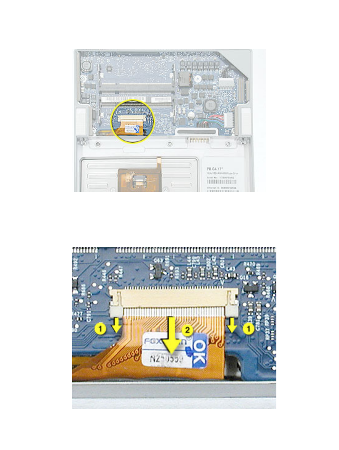
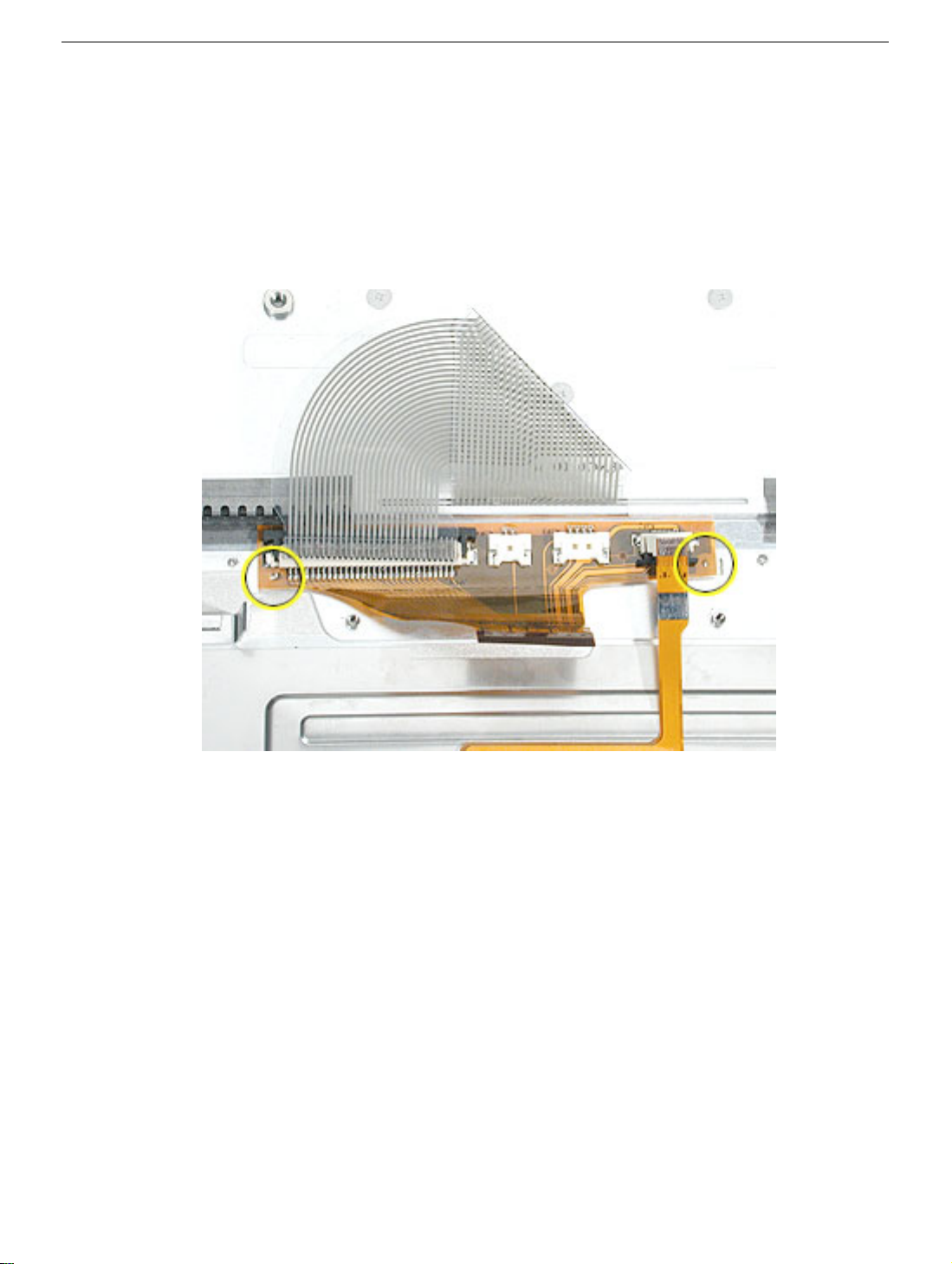
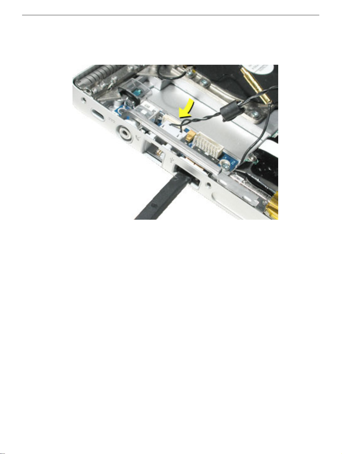
5. Locate the top case flex cable and ZIF connector.
6. Very carefully disconnect and remove the cable from the connector.
Important:
much force is used. (See “Zero Insertion Force Connectors” heading.)
The ZIF connector and locking bar are fragile and can easily break if too
Top Case
PowerBook G4 (17-inch) Take Apart -
19
Page 22
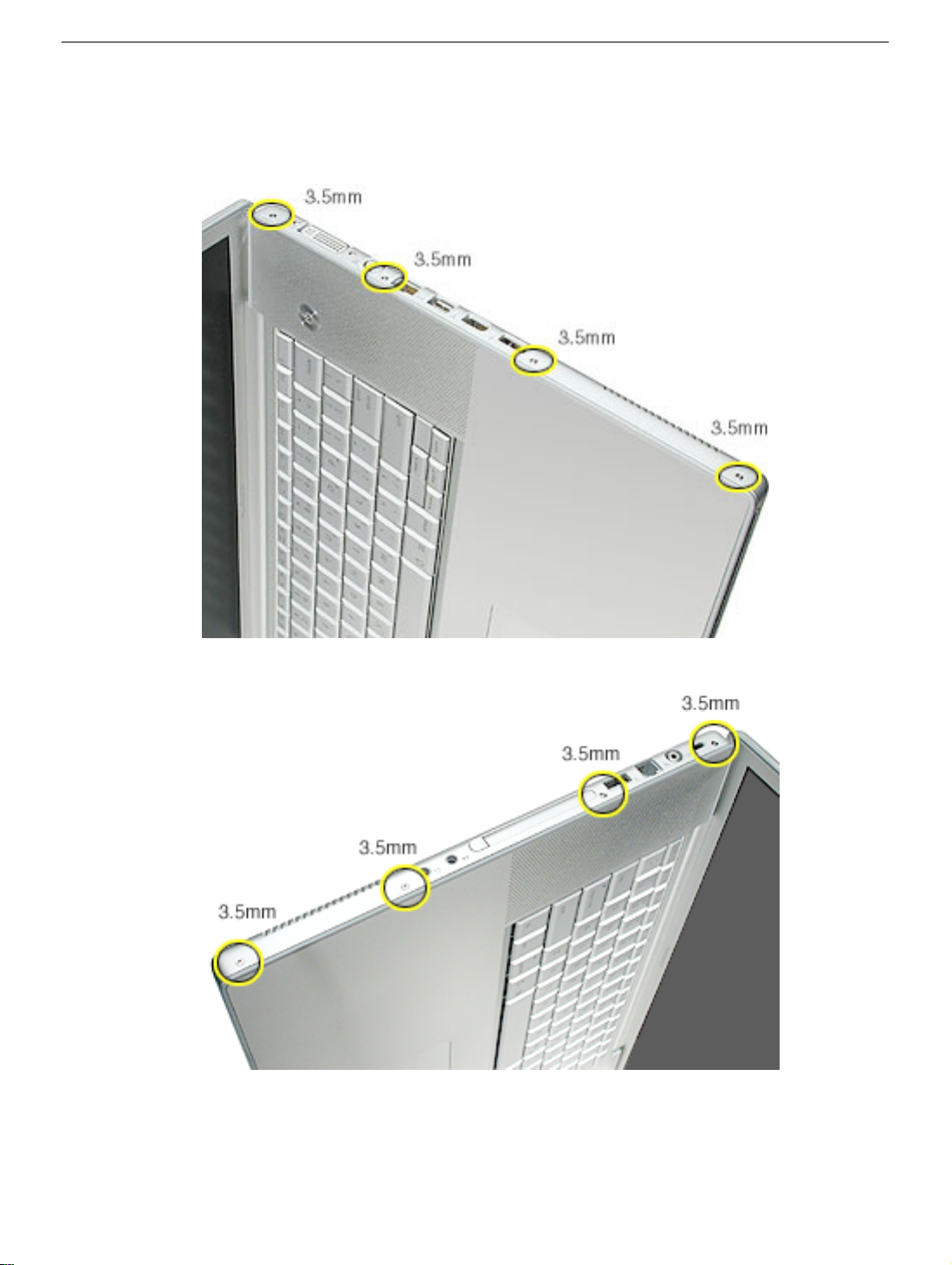
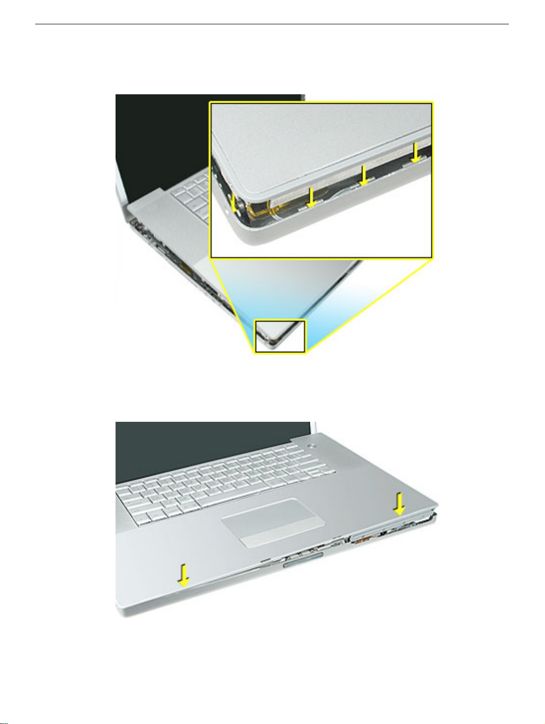
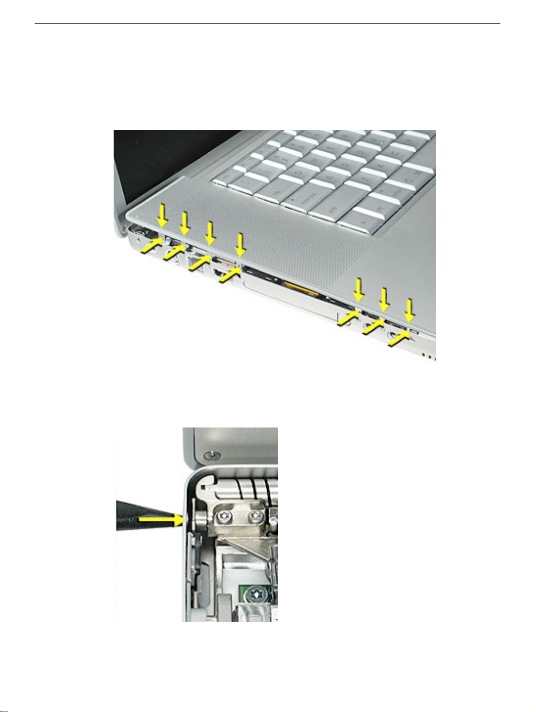
7. Open the display and place the computer on its side.
8. Remove four side screws from both sides.
20 -
PowerBook G4 (17-inch) Take Apart
Top Case
Page 23
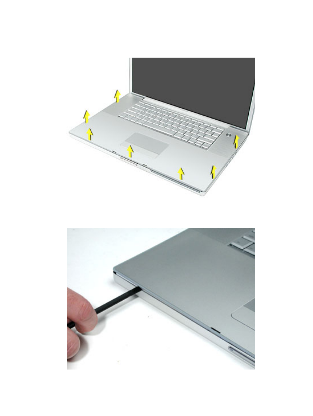
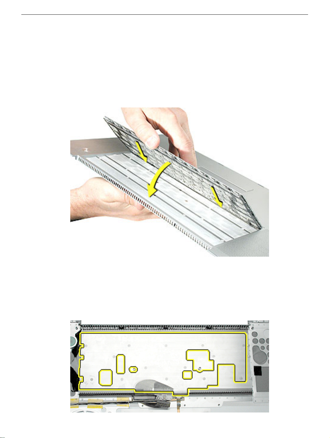
9. Turn the computer over.
10. Pull up on the top case along the sides and front until it releases.
Note:
A black stick inserted and twisted under the top case seam may be helpful.
Top Case
PowerBook G4 (17-inch) Take Apart -
21
Page 24
Replacement Procedure
Note:
If replacing the top case, remove the keyboard and set it aside to install onto the
replacement top case.
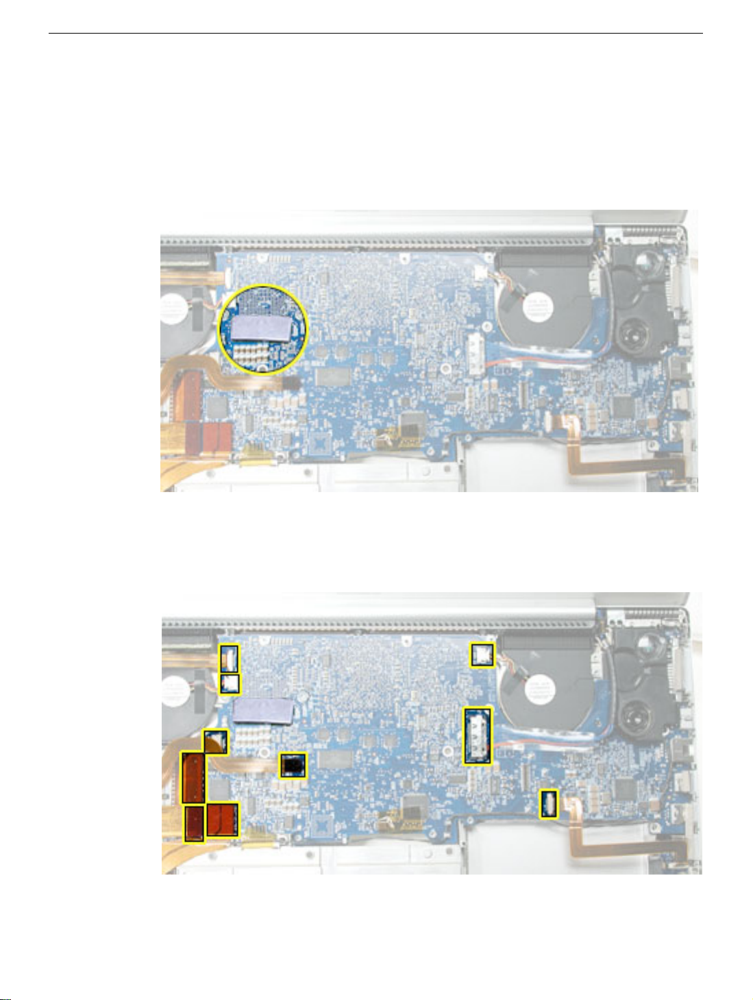
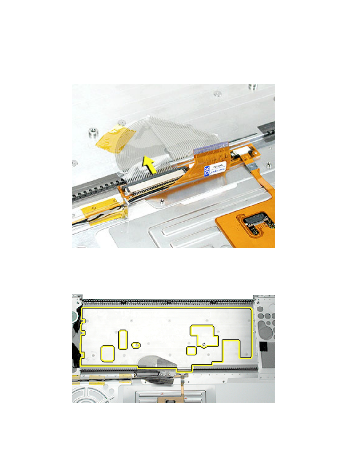
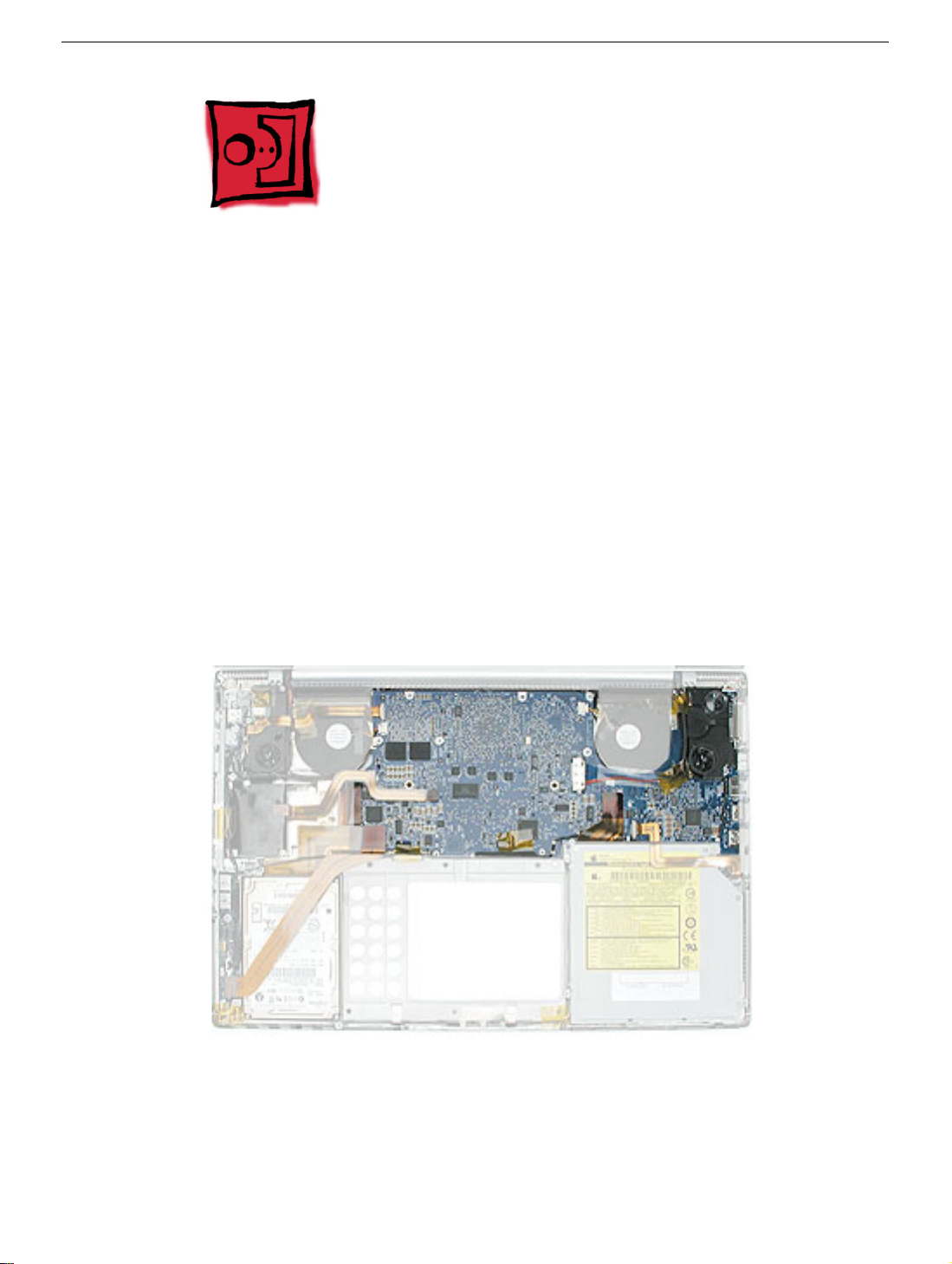
1. Verify the thermal pad shown here is in place. If not, check whether it is stuck under
the removed top case and replace. If not, install a new pad.
2. Visually check to verify that all cables (highlighted below) are connected and routed
correctly with nothing raised up or incorrectly over a component.
22 -
PowerBook G4 (17-inch) Take Apart
Top Case
Page 25
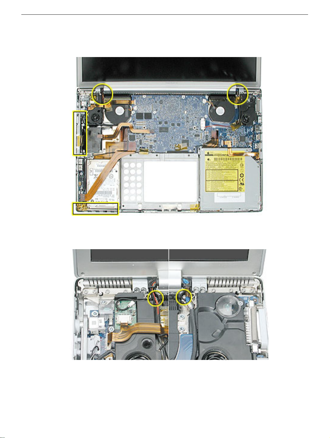
3. Check perimeter wiring, where shown, to verify that it will not be caught or pinched by
the top case during replacement.
4. Check that display cable brackets are properly seated and secured with screws.
Top Case
PowerBook G4 (17-inch) Take Apart -
23
Page 26
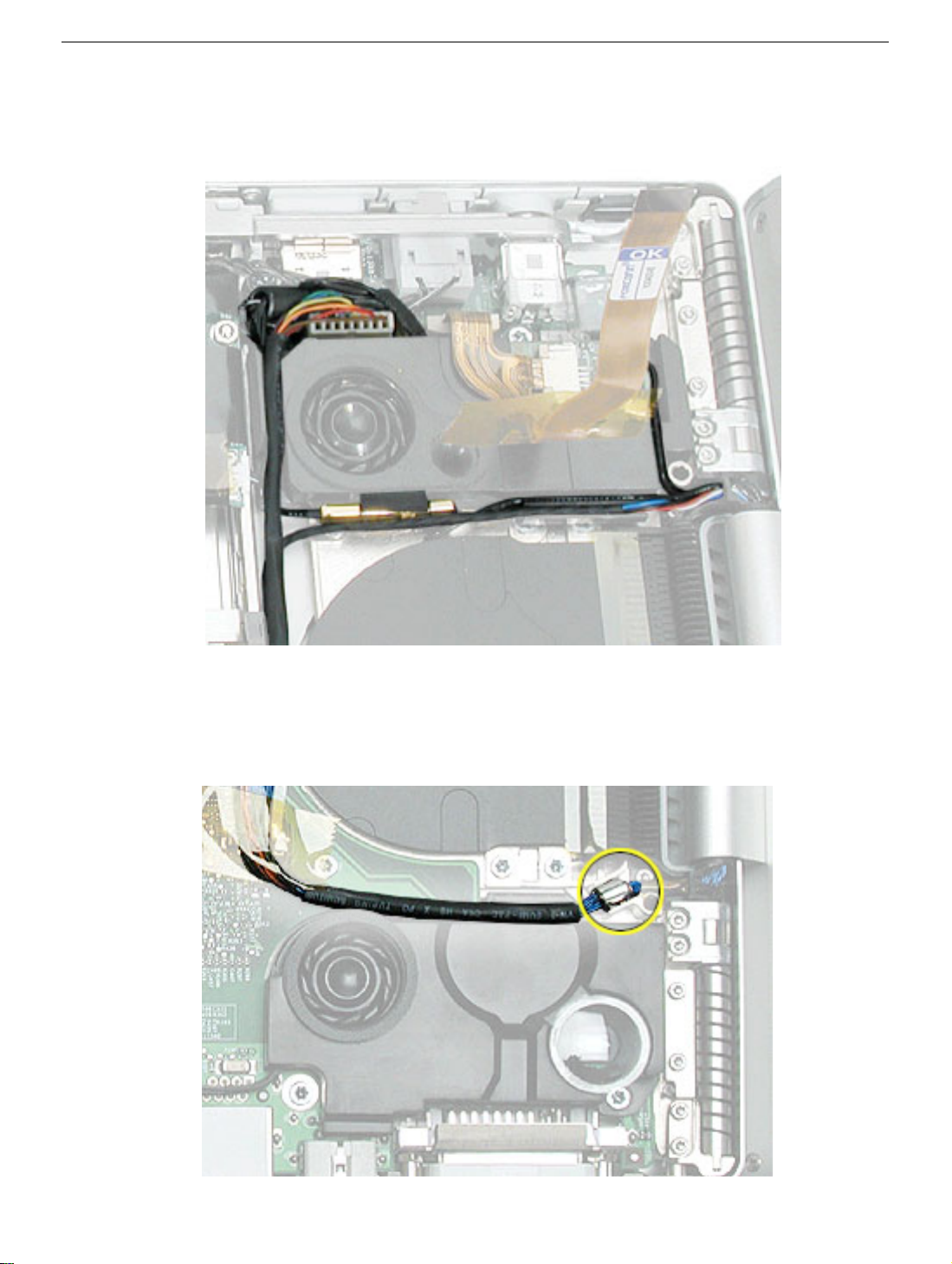
5. Verify that cables for Bluetooth, AirPort Extreme, inverter and power cable from the
DC-in board are routed and seated correctly in channels around the left speaker.
6. Verify that the LVDS cable’s metal bead fits into the metal channel (rounded side up so
that its teeth secure it) and that the cable is secured into the channel along the right
speaker.
24 -
PowerBook G4 (17-inch) Take Apart
Top Case
Page 27
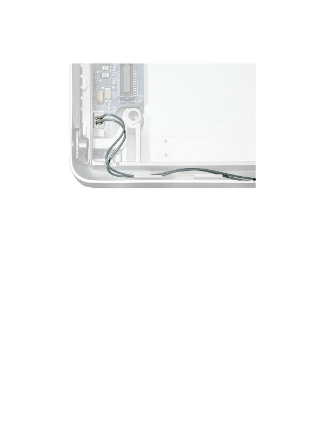
7. Verify that the sleep LED wires route over the notch in the frame (secure with Kapton
tape) and along the inside channel away from the front edge so that it will not be
damaged when replacing the top case.
8. Install the keyboard onto the top case.
Top Case
PowerBook G4 (17-inch) Take Apart -
25
Page 28
9. If the top case flex cable and connector assembly is not installed on the top case,
install it now.
Remove all adhesive, center the holes at both ends with the pins on the top case and
press into place, as shown below.
Note:
Make sure that the trackpad flex cable does not get caught under the
assembly.
26 -
PowerBook G4 (17-inch) Take Apart
Top Case
Page 29
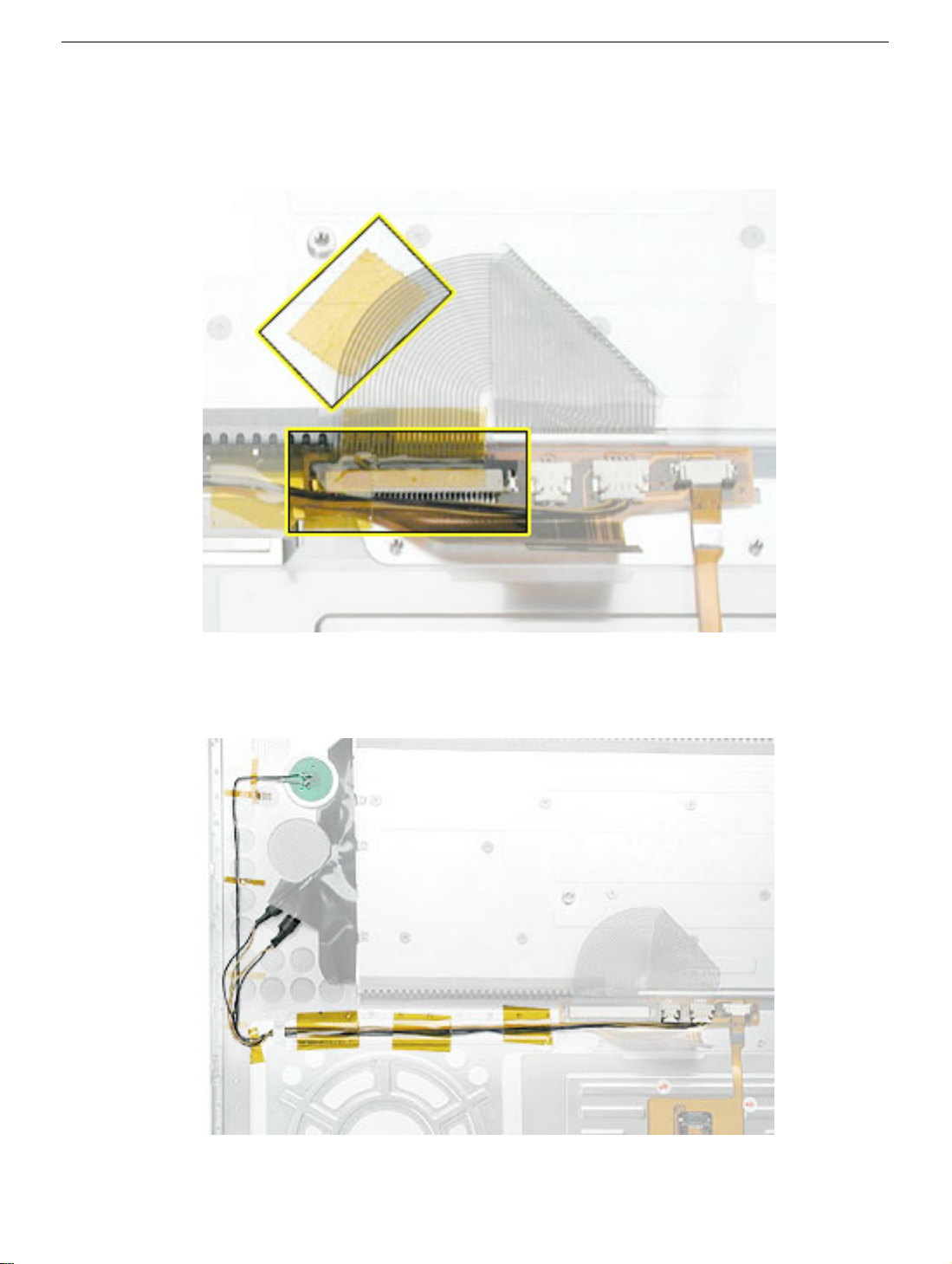
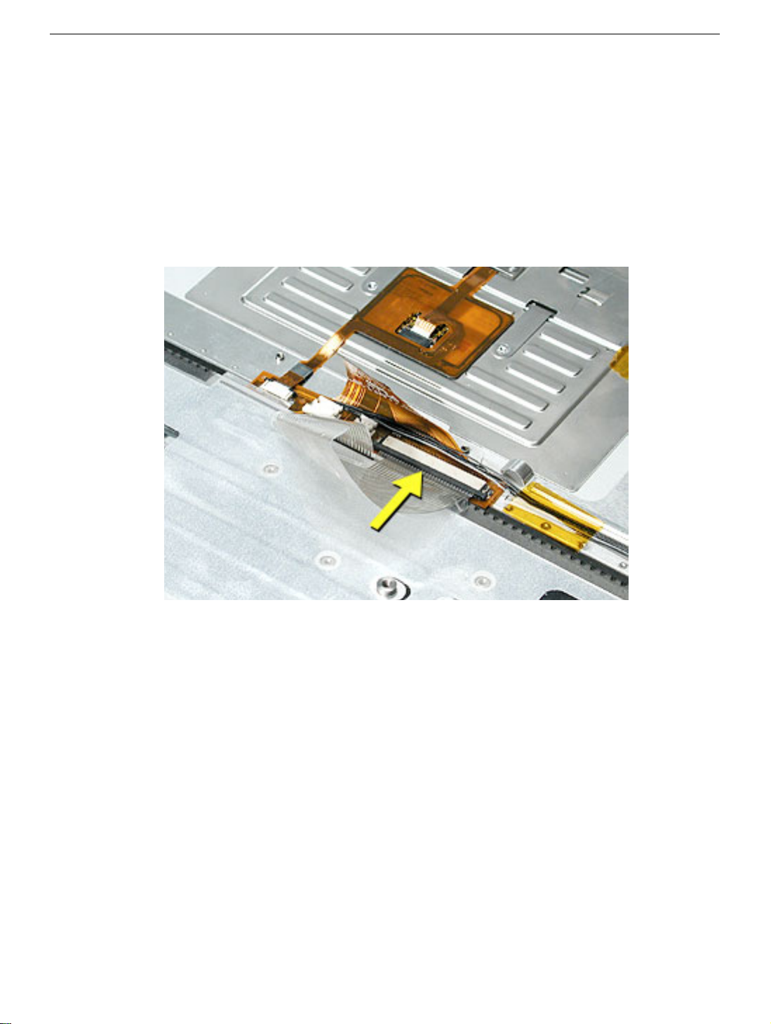
10. Connect the keyboard cable to its connector (the cable inserts under the ZIF
connector locking bar). Verify that the cable is fully inserted, square and straight.
Secure the cable and connector with Kapton tape.
11. Connect the power button and keyboard fiber optic wire connectors, route the wires as
shown and secure with Kapton tape.
Top Case
PowerBook G4 (17-inch) Take Apart -
27
Page 30
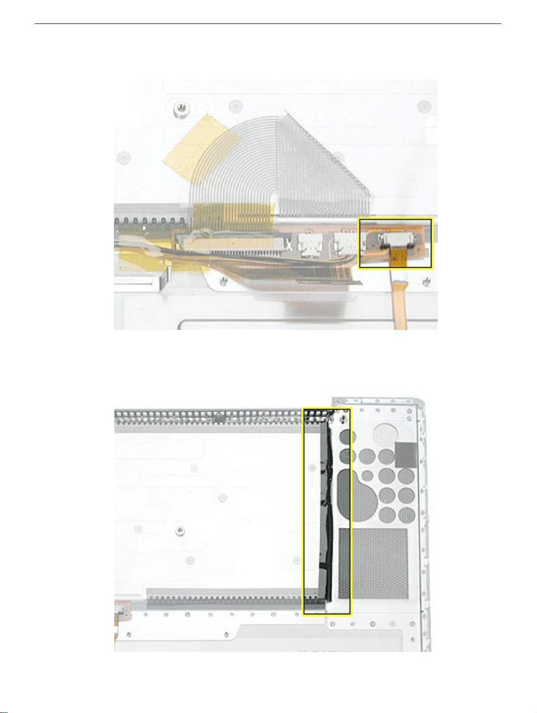
12. Connect the trackpad flex cable.
13. If not installed, install the strip of black mylar over the edge of the keyboard well to
prevent light leakage. Center the mylar over the edge, and top to bottom, as shown.
28 -
PowerBook G4 (17-inch) Take Apart
Top Case
Page 31

14. Check that the perimeter metal tabs are not bent.
Note:
Do not bend the tabs; the metal quickly fatigues and can break off easily.
Top Case
PowerBook G4 (17-inch) Take Apart -
29
Page 32

15. Lay the top case upside down and locate the flex cable.
16. While pulling the cable up, run a finger along its base to crease it at a 90-degree
angle.
17. The cable should point straight up.
30 -
PowerBook G4 (17-inch) Take Apart
Top Case
Page 33
18. Open the display to 90-degrees and tilt the computer back so it rests on the back of
the display.
19. Guide the top case flex cable through the slot between the logic board and the bottom
case frame.
Note:
For the following procedures, you will want to keep the top case close to the bottom
case so the flex cable will not pull out of the slot.
20. Turn the computer to rest on the bottom case.
Top Case
PowerBook G4 (17-inch) Take Apart -
31
Page 34
21. At the left front corner of the computer, insert the top case edges into the bottom case
channels, shown.
22. Hold the front of the top case along the front edge of the bottom case and lower into
place.
32 - PowerBook G4 (17-inch) Take Apart
Top Case
Page 35
23. Note: If the tabs along the sides of the top case catch on the bottom case, use a
narrow tool and work from front to back to carefully push or pull the tabs very slightly
to help slide them into place.
Important: The tabs are fragile. Do not apply too much pressure or bend them.
Note: Some side screws have a flexible screw boss. If they block a tab from seating,
use a narrow tool to push the boss slightly.
Top Case
PowerBook G4 (17-inch) Take Apart - 33
Page 36

Important: The top case should lay flat along the sides and top, if not, make sure
that cables and components are not interfering.
Also, make sure it is not held up by one of the metal tabs protruding down from the
top case. Carefully bend them slightly to fit if needed.
24. Install the front and rear side screws on both sides to hold the top case in place.
34 - PowerBook G4 (17-inch) Take Apart
Top Case
Page 37

25. Carefully close the display, without forcing. If it does not close easily, reinstall the top
case, checking for cable routing and clearances.
26. Turn the computer over.
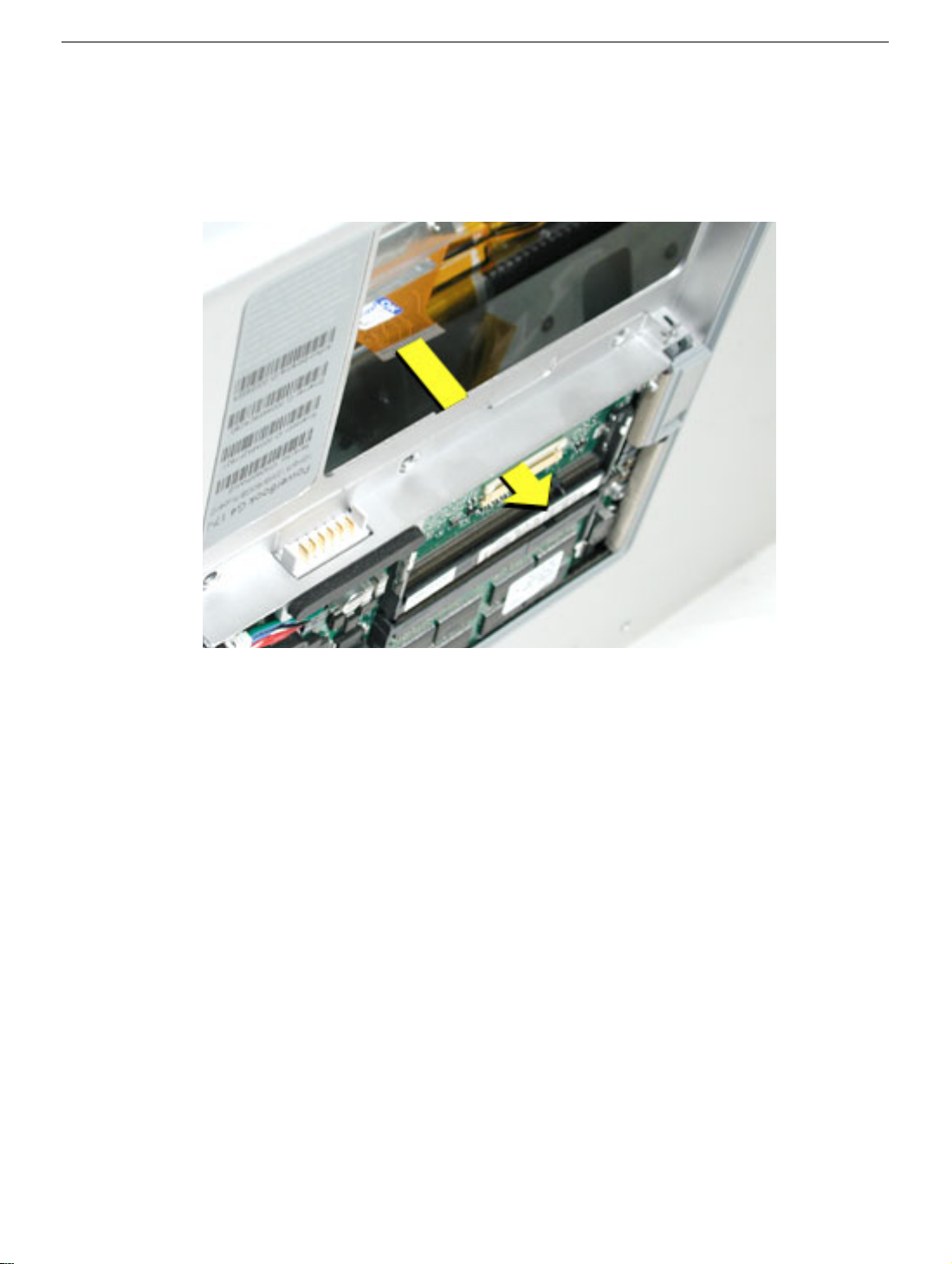
27. Check that the top case flex cable is still through the slot. If not, use the round shaft of
a small Phillips screwdriver to carefully pull it through, as shown.
Important: If the cable does not fully reach the ZIF connector, the cable is trapped
under the frame. Reinstall the top case.
Top Case
PowerBook G4 (17-inch) Take Apart - 35
Page 38

28. Carefully pull the locking bar of the ZIF connector out slightly. Slide the flex cable over
the locking bar and into the connector until it stops (the metal edge of the cable should
be parallel to the connector), then slide the locking bar in to secure it.
29. Check for a gap, as shown below, between the top and bottom case at the back right
side next to the hinge. This may indicate that the LVDS cable is trapped.
36 - PowerBook G4 (17-inch) Take Apart
Top Case
Page 39
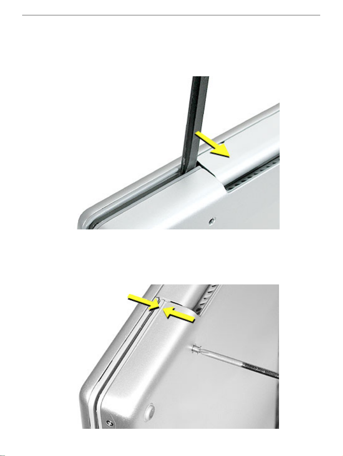
30. To check this, insert the flat-blade side of a black stick between the display and top
case then push toward the bottom case to see if the gap can be closed. If so, proceed
to next step. If not, remove the top case and check the routing of the LVDS cable, then
reinstall the top case.
31. Carefully install one of the “shoulder” screws in the end screw hole on the bottom.
Important: If the screw does not go in easily do not force it or damage may result.
Check the routing of the LVDS cable and reinstall the top case.
Top Case
PowerBook G4 (17-inch) Take Apart - 37
Page 40

32. Install the other “shoulder” screw in the end screw hole.
33. Install the remaining side screws.
34. Install the logic board screws.
35. Install the remaining bottom screws along the back edge.
36. Install the memory door, and screws.
37. Install the battery bay screws.
38. Visually check the flatness of the top case. If it is not flat, remove it, fix the problem,
then reinstall.
39. Replace the battery.
40. Testing the computer should include powering on, checking the keyboard and
trackpad function, and operate the computer in a dimly lit room to check that the
keyboard backlight is working.
38 - PowerBook G4 (17-inch) Take Apart
Top Case
Page 41

Keyboard
Tools
This procedure requires the following tools:
• #0 Phillips screwdriver
• Torx T8 screwdriver (or other blunt tool, 3.5mm wide or less)
• Black stick (or other nonconductive nylon or plastic flat-blade tool)
Part Location
Keyboard
Preliminary Steps
Before you begin, remove the following:
• Battery
• Top case
PowerBook G4 (17-inch) Take Apart - 39
Page 42
Procedure
1. Turn the top case over, locate the keyboard flex cable and remove the Kapton tape
holding the cable.
2. Carefully release the locking bar of the cable’s ZIF connector and pull out the cable.
3. Locate and carefully peel off the insulator film over keyboard screws and reserve for
reinstallation.
40 - PowerBook G4 (17-inch) Take Apart
Keyboard
Page 43

4. Remove remaining adhesive, if any, from the top case and screw heads.
5. Remove the fourteen identical screws.
6. Start at the power button side and use a blunt tool (no wider than 3.5 mm) to carefully
push on the keyboard screw bosses through the boss holes to begin to release the
keyboard from its adhesive.
Important: To avoid damaging the screw boss threads, do not use a narrow tool that
will fit into the screw hole.
Keyboard
PowerBook G4 (17-inch) Take Apart - 41
Page 44

7. Continue until the keyboard can be grasped, then carefully lift it up and guide out its
flex cable (shown below).
42 - PowerBook G4 (17-inch) Take Apart
Keyboard
Page 45

8. Carefully rub off any adhesive residue left in the keyboard well and on the fiber optics.
Keyboard
PowerBook G4 (17-inch) Take Apart - 43
Page 46
Replacement Procedure
1. To install the keyboard or replacement keyboard, insert its flex cable through the slot in
the top case and rest the bottom of the keyboard evenly along the bottom edge of the
keyboard well.
2. Remove the protective cover from the adhesive strips on the keyboard. While keeping
the bottom of the keyboard flush along the bottom, lay the keyboard into place so that
the screw bosses fit into the boss holes.
3. Install the keyboard screws.
4. Replace the insulator film, avoiding wrinkles or bulges.
Important: The film must be installed and in the same location to protect against
contact and electrical shorting in certain areas and to allow contact with the EMI
spring on the logic board.
44 - PowerBook G4 (17-inch) Take Apart
Keyboard
Page 47
5. If replacing the existing keyboard, such as during a top case replacement, secure the
end of the keyboard flex cable. (The cable inserts under the ZIF connector locking
bar.)
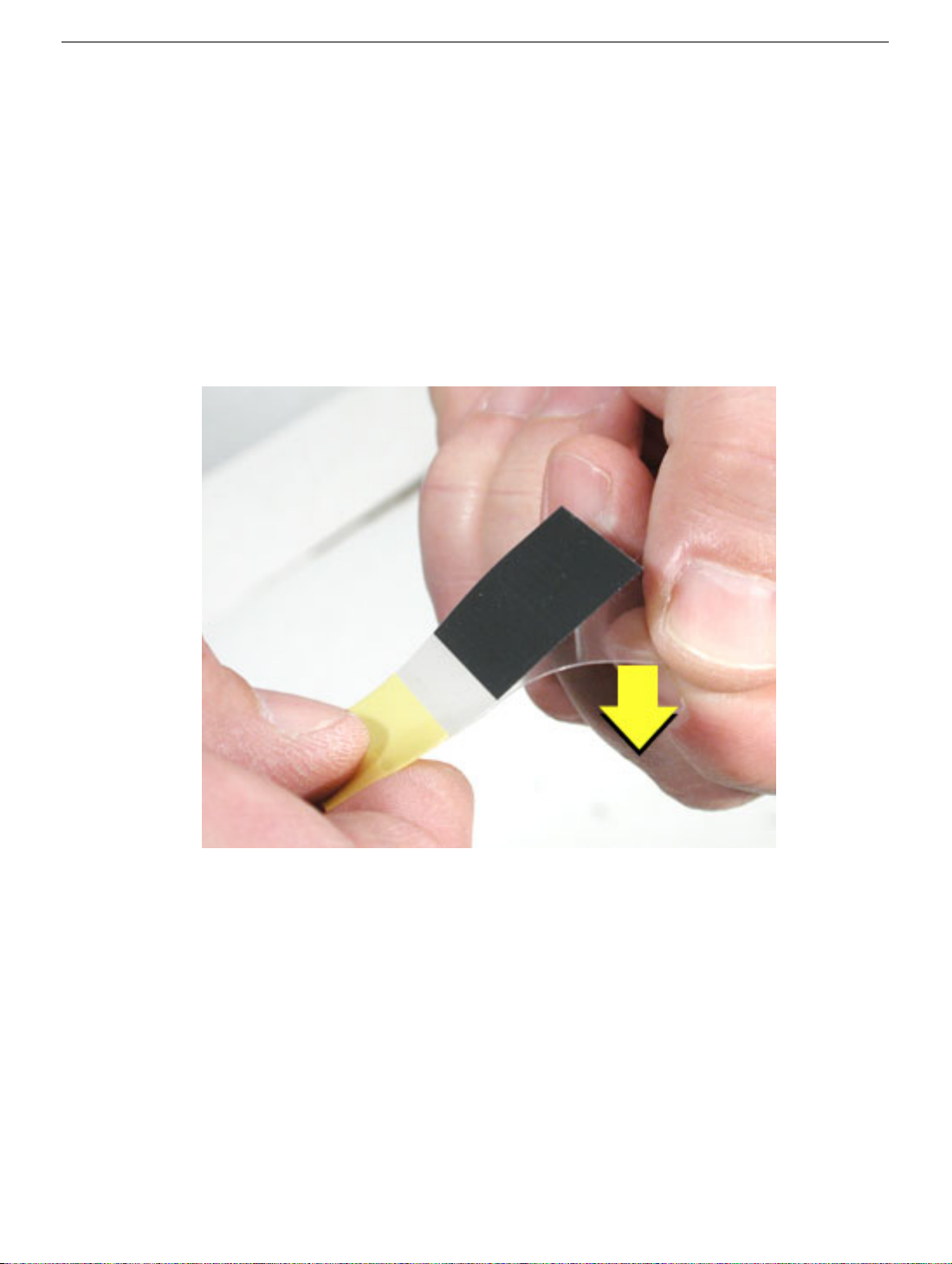
6. If installing a replacement keyboard, first remove the cable’s adhesive protector, then
turn the cable under itself (so the adhesive is on the inside of the loop but do not
secure the adhesive).
Secure the end of the keyboard flex cable into the ZIF connector. (The cable inserts
under the ZIF connector locking bar.)
Keyboard
PowerBook G4 (17-inch) Take Apart - 45
Page 48

7. Fold the cable flat and secure it’s adhesive by firmly holding the left side (to prevent
cable movement) while sliding your right hand fingers forward on the right side.
8. Use Kapton tape to secure the cable flat at the fold.
46 - PowerBook G4 (17-inch) Take Apart
Keyboard
Page 49

9. Verify that the cable is still fully inserted, straight and secure in the connector.
10. Turn over the top case and inspect the left and right sides of the keyboard. Push any
Mylar down along the sides of the keyboard.
11. Reassemble the computer.
12. Testing the computer should include powering on, checking the keyboard and
trackpad function.
In a darkened room, check for keyboard backlight function, and light leakage around
the perimeter of the keyboard, speaker grill openings and side ports.
Keyboard
PowerBook G4 (17-inch) Take Apart - 47
Page 50

Hard Drive
Tools
This procedure requires the following tools:
• Torx T8 screwdriver (magnetized)
• #1 Phillips screwdriver (magnetized)
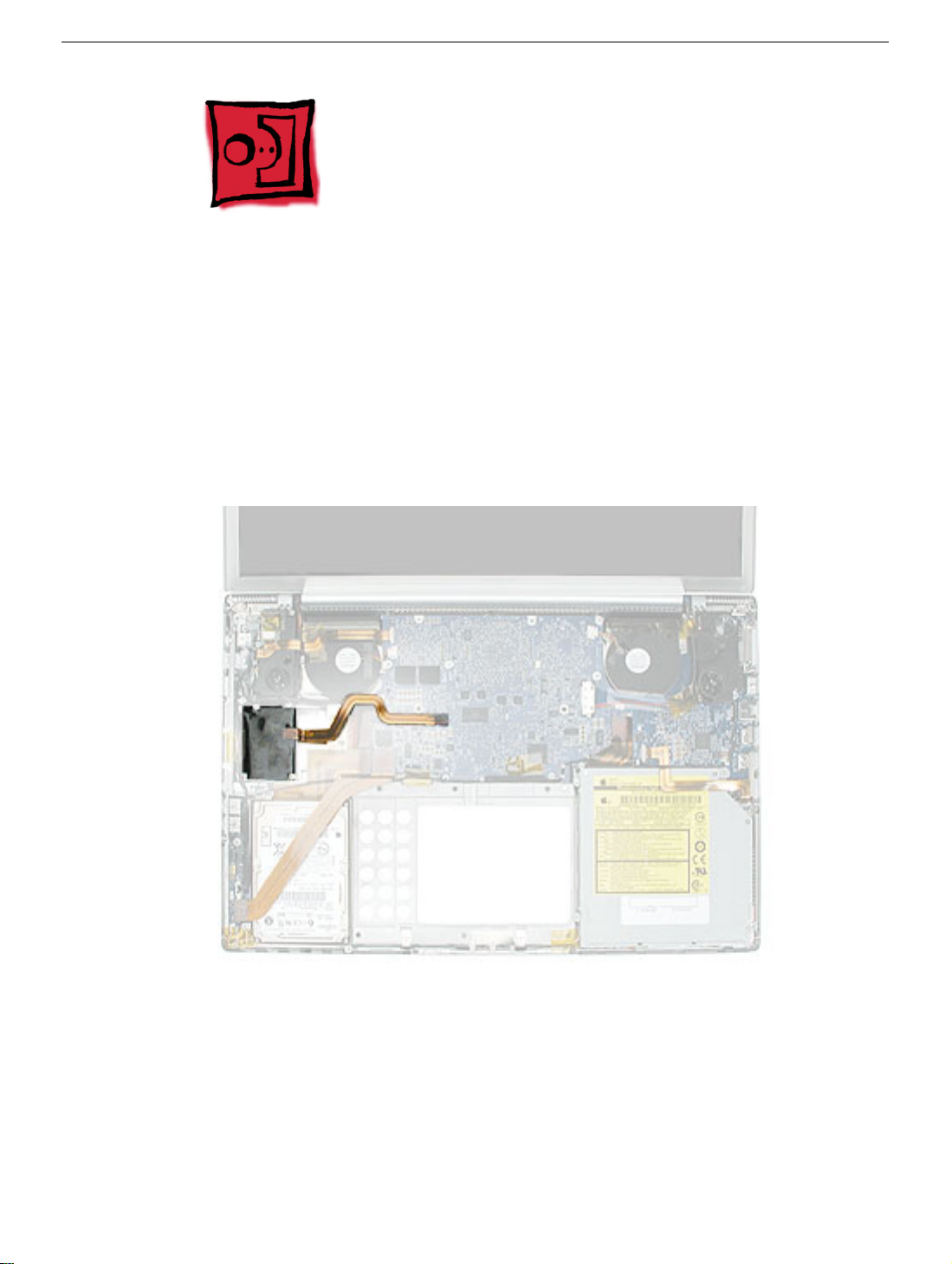
Part Location
Preliminary Steps
Before you begin, remove the following:
• Battery
• Top case
48 - PowerBook G4 (17-inch) Take Apart
Hard Drive
Page 51

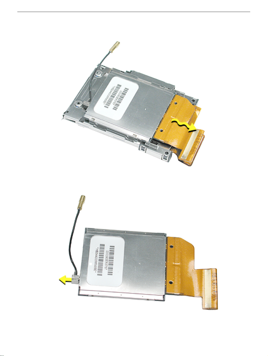
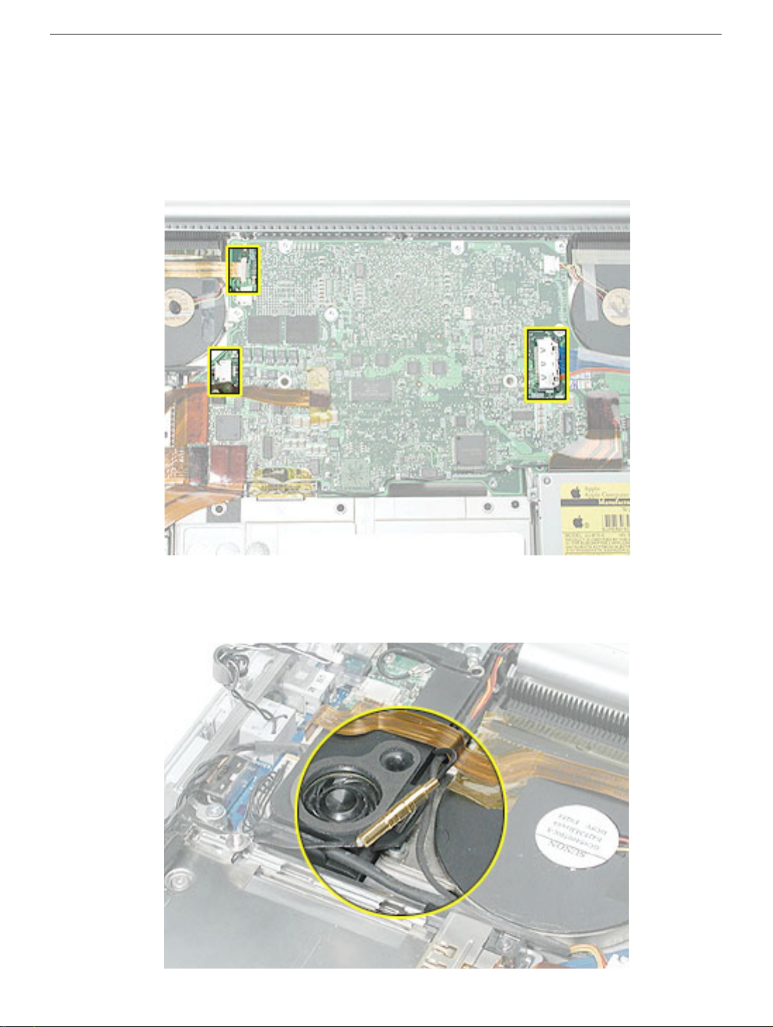
Procedure
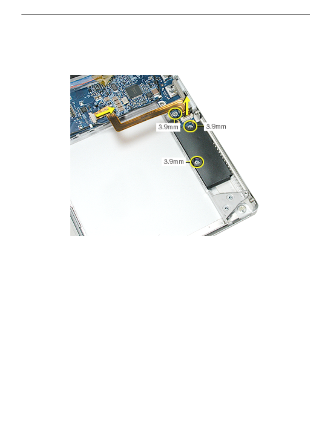
1. Use the tabs on the connectors to disconnect and remove the sound board flex cable.
Note: Remove the connector from the logic board by rocking from side to side.
2. Disconnect the hard drive flex cable.
3. Remove the four screws.
4. Lift out the hard drive (guide the flex cable under the speaker cables if necessary).
Hard Drive
PowerBook G4 (17-inch) Take Apart - 49
Page 52

5. Transfer brackets, side screws, rubber shockpads and the flex cable to the
replacement hard drive.
6. Install the replacement hard drive, and reassemble the computer.
7. Testing the computer should include powering on, checking that the hard drive is
recognized, checking for sound from the speakers and that the sleep LED light works.
50 - PowerBook G4 (17-inch) Take Apart
Hard Drive
Page 53

Sound Board
Tools
This procedure requires the following tools:
• Torx T8 screwdriver (magnetized)
• Black stick (or other nonconductive nylon or plastic flat-blade tool)
Part Location
Sound Board
Preliminary Steps
Before you begin, remove the following:
• Battery
• Top case
• Hard drive
PowerBook G4 (17-inch) Take Apart - 51
Page 54

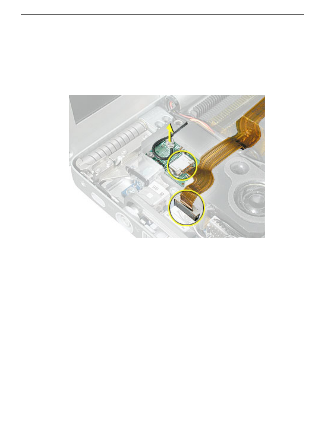
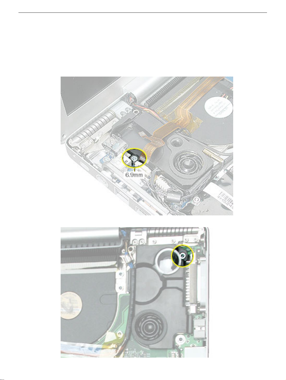
Procedure
1. Disconnect the speaker wires connector and sleep LED connector.
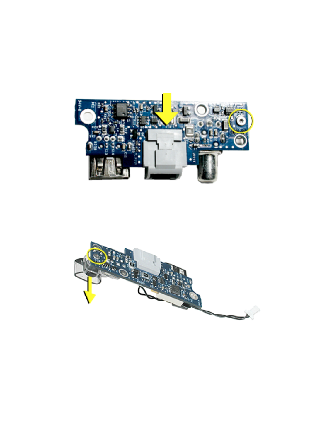
2. Remove the two screws.
3. Pull the sound board out starting at the ports end.
52 - PowerBook G4 (17-inch) Take Apart
Sound Board
Page 55

Replacement Note: To prevent damage to the sleep LED wires during top case
reassembly, verify that the wires route over the notch in the frame (secure with Kapton
tape here and over connector) and then along the inside channel away from the front
edge.
4. Install the replacement sound board, and reassemble the computer.
5. Testing the computer should include powering on, checking for sound from the
speakers and that the sleep LED light works. The headphone and line in ports should
be checked.
Sound Board
PowerBook G4 (17-inch) Take Apart - 53
Page 56

SuperDrive
Tools
This procedure requires the following tools:
• Torx T8 screwdriver (magnetized)
• #1 Phillips screwdriver (magnetized)
Part Location
Preliminary Steps
Before you begin, remove the following:
• Battery
• Top case
54 - PowerBook G4 (17-inch) Take Apart
SuperDrive
Page 57

Procedure
1. Grasp the SuperDrive flex cable connector, where shown, and rock from side to side
while pulling up, to disconnect it.
Warning: Do not pull up on the end of the flex cable connector or the cable may
separate from the connector.
2. Remove the four screws.
3. Carefully lift and guide the drive out.
Important: Avoid pulling on the backup battery flex cable.
SuperDrive
PowerBook G4 (17-inch) Take Apart - 55
Page 58

4. Transfer the flex cable, brackets and screws to the replacement SuperDrive.
5. Install the replacement SuperDrive, and reassemble the computer.
6. Testing the computer should include powering on, inserting a CD and ejecting it to
make sure the drive is aligned with the opening and functioning properly.
56 - PowerBook G4 (17-inch) Take Apart
SuperDrive
Page 59

Backup Battery Board
Tools
This procedure requires the following tools:
• Torx T8 screwdriver (magnetized)
• Black stick (or other nonconductive nylon or plastic flat-blade tool)
Part Location
Preliminary Steps
Before you begin, remove the following:
• Battery
• Top case
• SuperDrive
Backup Battery Board
PowerBook G4 (17-inch) Take Apart - 57
Page 60
Procedure
1. Release the two ZIF connectors and remove the flex cable.
2. Remove the three screws.
3. Install the replacement backup battery board.
4. Reassemble the computer.
5. Testing the computer should include plugging in the power adapter and letting the
backup battery charge for half an hour. Then power on the computer and disconnect
the power adapter, set the system clock, put the computer to sleep, remove the main
battery for five seconds and reinstall. The time should not reset. Also, check the right
side USB port which is on the backup battery board.
58 - PowerBook G4 (17-inch) Take Apart
Backup Battery Board
Page 61
Modem
Tools
This procedure requires the following tools:
• 4 mm socket wrench
• Needlenose pliers (helpful to reinstall hex nuts)
Part Location
Modem
Preliminary Steps
Before you begin, remove the following:
• Battery
• Top case
PowerBook G4 (17-inch) Take Apart - 59
Page 62

Procedure
1. Disconnect the modem flex cable.
2. Remove the three hex nuts.
3. Lift the modem up slightly and disconnect the RJ-11 cable connector.
4. Install the replacement modem, and reassemble and test the computer.
60 - PowerBook G4 (17-inch) Take Apart
Modem
Page 63

PC Card Cage and AirPort Extreme Assembly
Tools
This procedure requires the following tools:
• #0 Phillips screwdriver (magnetized)
• Torx T6 screwdriver (magnetized)
• Black stick (or other nonconductive nylon or plastic flat-blade tool)
Part Location
Preliminary Steps
Before you begin, remove the following:
• Battery
• Top case
• Modem
PC Card Cage and AirPort Extreme Assembly
PowerBook G4 (17-inch) Take Apart - 61
Page 64

Procedure
1. Turn the computer over and remove the rubber gasket on the AirPort Extreme flex
cable connector and reserve for reinstallation. Disconnect the connector.
2. Turn the computer over and disconnect the PC card cage and hard drive flex cables.
62 - PowerBook G4 (17-inch) Take Apart
PC Card Cage and AirPort Extreme Assembly
Page 65

3. Pull out the coupling (joining the AirPort Extreme jumper and antenna cable) from the
channel in the side of the left speaker. Grasp the coupling (not the wires) at both ends
and pull to separate it at the middle.
4. Remove two Phillips screws and two Torx T6 screws.
PC Card Cage and AirPort Extreme Assembly
PowerBook G4 (17-inch) Take Apart - 63
Page 66

5. Important: The cross piece at the front end of the PC card cage is fragile. To avoid
damage, do not touch this area while maneuvering the assembly.
Lift up on the sides of the PC card cage assembly and carefully guide the AirPort
Extreme card flex cable connector from under the logic board.
Important: To avoid damage, do not allow the pins of the AirPort Extreme card cable
connector to rub along the logic board. If the clearance is too tight, try slightly loosening a
couple of the logic board screws on this side, but do not bend the board. If this doesn’t
work, the logic board will have to be removed to continue.
6. Slide out the PC card cage eject button.
7. Turn over the PC card cage to locate the AirPort Extreme card.
8. Pull on the AirPort Extreme card flex cable to slide the card out of the PC card cage.
64 - PowerBook G4 (17-inch) Take Apart
PC Card Cage and AirPort Extreme Assembly
Page 67
Note: Wiggling the card from side to side slightly may help to release it.
9. If replacing the AirPort Extreme card, pull the antenna jumper connector straight back
to remove it. Transfer the cable extension to the replacement AirPort Extreme card.
10. Install the AirPort Extreme card onto the PC card cage to be installed and reinstall the
assembly.
PC Card Cage and AirPort Extreme Assembly
PowerBook G4 (17-inch) Take Apart - 65
Page 68

Replacement Note: Ensure that the pin on the PC card cage eject button is secured
by the hole in the cage mechanism.
11. Reassemble the computer.
12. Testing the computer should include inserting a PC card to check that it can be locked
in and that the eject button works smoothly. Use Apple System Profiler to check that
the AirPort Extreme card and modem are recognized. Test that the AirPort Extreme
card is working and that the modem can dial out.
66 - PowerBook G4 (17-inch) Take Apart
PC Card Cage and AirPort Extreme Assembly
Page 69

Bluetooth
Tools
This procedure requires the following tools:
• Torx T6 screwdriver (magnetized)
• Black stick (or other nonconductive nylon or plastic flat-blade tool)
Part Location
Bluetooth
Preliminary Steps
Before you begin, remove the following:
• Battery
• Top case.
PowerBook G4 (17-inch) Take Apart - 67
Page 70
Procedure
1. Release the two ZIF connectors and move the flex cable aside.
2. Disconnect the Bluetooth antenna cable.
Replacement Note: Make sure the antenna cable is secured in the channel on the
speaker.
68 - PowerBook G4 (17-inch) Take Apart
Bluetooth
Page 71

3. Remove the screw and Bluetooth board.
4. Install the replacement Bluetooth board, and reassemble the computer.
5. Testing the computer should include using Bluetooth to connect to another computer.
Check the function of the DC-in port and the left USB port.
Bluetooth
PowerBook G4 (17-inch) Take Apart - 69
Page 72

Speakers
Tools
This procedure requires the following tools:
• Torx T8 screwdriver (magnetized)
• Black stick (or other nonconductive nylon or plastic flat-blade tool)
Part Location
Preliminary Steps
Before you begin, remove the following:
• Battery
• Top case
• Bluetooth board
70 - PowerBook G4 (17-inch) Take Apart
Speakers
Page 73
Procedure
Note: Lift up any Kapton tape as necessary and reserve for replacement.
1. Pull wires out of routing channels on the left speaker.
2. Remove one screw on each speaker.
Speakers
PowerBook G4 (17-inch) Take Apart - 71
Page 74

3. Lift out speakers.
4. Deroute the speaker wires along logic board.
Replacement Note: Verify proper routing of speaker cables under securing clips.
5. Disconnect the speaker wire connector from the sound board.
6. Install the replacement speakers, and reassemble the computer.
7. Testing the computer should include using the Sound system preference pane to test
the left and right speakers.
72 - PowerBook G4 (17-inch) Take Apart
Speakers
Page 75

DC-In Board
Tools
This procedure requires the following tools:
• Torx T8 screwdriver (magnetized)
• Black stick (or other nonconductive nylon or plastic flat-blade tool)
Part Location
DC-In Board
Preliminary Steps
Before you begin, remove the following:
• Battery
• Top case
• Left speaker
PowerBook G4 (17-inch) Take Apart - 73
Page 76

Procedure
1. Disconnect the RJ-11 connector to the modem.
2. Disconnect the power cable on the DC-in board.
3. Remove the two screws.
4. Insert a black stick under the DC-in board to help guide it out.
74 - PowerBook G4 (17-inch) Take Apart
DC-In Board
Page 77
Replacement Note: Make sure that the replacement DC-in board includes the RJ-11 port
and ambient light sensor cover. If not transfer them from the original board to the
replacement board.
The RJ-11 port slides off the DC-in board but may be very tight. It may be helpful to pull on
the port until it begins to move, then use a black stick to create leverage behind the port.
The ambient light sensor cover slides on and is attached with a screw from underneath the
board.
DC-In Board
PowerBook G4 (17-inch) Take Apart - 75
Page 78
5. Install the replacement DC-in board, and reassemble the computer.
Note: Insert a black stick into the USB port opening to guide the board into place.
6. Testing the computer should include using Bluetooth to connect to another computer.
Check the function of the modem port, DC-in port and the left USB port.
76 - PowerBook G4 (17-inch) Take Apart
DC-In Board
Page 79
Logic Board
Tools
This procedure requires the following tools:
• Torx T8 screwdriver (magnetized)
• 1600 watt hair dryer
• Razor knife with a new flat-blade
• Black stick (or other nonconductive nylon or plastic flat-blade tool)
• Thermal Pad Kit (076-1033)
• T630 thermal gel (922-5929).
Note: To organize the screws you remove from the computer, use a tray with divided
compartments (such as a plastic ice cube tray).
Part Location
Logic Board
PowerBook G4 (17-inch) Take Apart - 77
Page 80

Preliminary Steps
Before you begin run the computer until warm (if possible) to help soften the thermal
materials on the logic board, then shut it down and remove the following:
• Battery
• Top case
• SuperDrive
• Right speaker
Procedure
Warning: Flexing of the logic board can break solder joints to chips. To prevent
damage to the board, guard against unnecessary flexing. Do not hold the board by
the ports end or by the narrow neck at the fan cutout, as the board’s weight can flex
the board at this narrow point.
1. Turn the computer over. Disconnect the cables shown.
78 - PowerBook G4 (17-inch) Take Apart
Logic Board
Page 81

2. Turn the computer over. Disconnect the cables shown.
3. Remove the twelve screws.
Logic Board
PowerBook G4 (17-inch) Take Apart - 79
Page 82

4. Important: To prevent damage to the logic board chips, the thermal material between
the logic board and the heatsink must be softened before removing the logic board.
Use the following procedure:
• Remove all memory cards and leave the memory door off.
• Verify all screws have been removed.
• Verify all cables are disconnected and moved away from the procedure area
shown below.
• Turn on a 1600 watt hair dryer and set it to high. Move the dryer back and forth
continuously, left to right, about one second per cycle, over the area shown below,
holding it about 20 mm (about 1-inch) above the board, for approximately one and
a half minutes. (The temperature should reach approximately 75-80-degrees C
(167-176-degrees F).)
• After at least 45-seconds, and while continuing to move the hair dryer as described
above, insert a black stick just under the left edge of the logic board, where shown
below, and apply slight upward pressure (do not pry). Continue the hair dryer
procedure along with the slight upward pressure on the board until the thermal
material releases and the board moves up easily.
• Once the thermal material has released, discontinue using the hair dryer.
• Continue to the next step before the thermal material cools.
Warning: Do not use a heat gun, or damage can result.
80 - PowerBook G4 (17-inch) Take Apart
Logic Board
Page 83

5. Lift the logic board from the left side and pivot along the port side.
Note: The thermal material should easily release. If not, repeat the hair dryer
procedure, above (verify that all the screws have been removed). Apply slow
constant pressure until it releases, avoid over flexing.
Warning: Flexing the logic board can break solder joints to chips. Avoid
unnecessary flexing especially at the narrow neck of the fan cutout.
6. Carefully coax the port end of the board out of the port openings.
Note: The DVI connector may catch on the part of the frame shown here. Carefully
maneuver it until it releases.
Logic Board
PowerBook G4 (17-inch) Take Apart - 81
Page 84

Replacement Procedure
Warning: Flexing of the logic board can break solder joints to chips. To prevent
damage to the board, guard against unnecessary flexing. Do not hold the board by
the ports end or by the narrow neck at the fan cutout, as the board’s weight can flex
the board at this narrow point.
1. Verify that the replacement logic board has EMI shields attached, as shown. If not,
transfer the shields from the replaced board, or replace with a new shield kit.
82 - PowerBook G4 (17-inch) Take Apart
Logic Board
Page 85

2. On the back side of the logic board, remove the existing rectangular thermal pad
covering two chips, shown below.
Important: If the pad is not on the board, check the underside of the top case and
remove.
3. From the Thermal Pad Kit (076-1033) install the rectangular shaped pad over the two
chips on the replacement logic board, where shown below.
Note: Avoid unnecessary contact with either side of the thermal pad as dirt and body
oils reduce the thermal pad's conductivity.
Logic Board
PowerBook G4 (17-inch) Take Apart - 83
Page 86

4. Use a black stick to remove all the original thermal material on the heatsink at the
locations shown below.
5. Vigorously clean remaining residue and adhesive with an alcohol pad.
Warning: Whenever the logic board is separated from the heatsink, you must
remove all existing thermal material and install new thermal material to the heatsink
at the three locations shown above. Failure to do so can cause the computer to
overheat and be damaged.
Important: If a replacement logic board comes with thermal pads installed, you will only
need to install Thermal Gel (922-5929) to the center surface of the heatsink.
84 - PowerBook G4 (17-inch) Take Apart
Logic Board
Page 87
Note: Avoid unnecessary contact with thermal gel or either side of thermal pads as dirt
and body oils reduce the thermal pad's conductivity.
6. From the Thermal Pad Kit (076-1033), center and install the square thermal pads on
the heatsink as follows:
• Smaller square pad on the left most mating surface
• Larger square pad on the right most mating surface (if the kit includes two same-
size pads, apply them, with the backing removed, one on top of the other as a
double layer)
Note: To install a thermal pad, remove the protective backing from one side of the
pad.
Logic Board
PowerBook G4 (17-inch) Take Apart - 85
Page 88

Center that side over the mating surface (raised surface) and evenly apply it, without
air pockets, by lightly pressing on the protective backing of the other side.
Remove the remaining protective backing.
Important: With an razor knife, trim any excess thermal pad material that extends
beyond the mating surface, if necessary, to prevent it from touching holes in the
heatsink.
86 - PowerBook G4 (17-inch) Take Apart
Logic Board
Page 89

7. Apply approximately 0.3 to 0.5 cubic centimeter (cc) of T630 thermal gel (922-5929) to
the center of the center mating surface on the heatsink. (The 10 cc dispenser may be
graduated in milliliters. Note: A milliliter (ml) is the same as a cubic centimeter (cc)).
Note: To apply the thermal gel from the 10 cubic centimeter (cc) dispenser, remove
the end cap and push the plunger until the gel reaches the front opening. Note the
position of the end of the plunger in the tube. Dispense the gel until the plunger end
moves about 1/3 to 1/2 of 1 cc (ml). The plunger will move back slightly when
pressure is released, so push it slightly beyond the amount to be dispensed.
Logic Board
Note: After installing new thermal material, if you must briefly re-separate the logic board
from the heatsink, it is OK to retain the same, new material, as long as they are not
handled excessively.
PowerBook G4 (17-inch) Take Apart - 87
Page 90

8. If the logic board was removed to facilitate another procedure and will be reinstalled,
also remove all the thermal material from the corresponding chips (shown below) in
the same manner.
Important: Use extreme care not to damage the chips or logic board components.
88 - PowerBook G4 (17-inch) Take Apart
Logic Board
Page 91

9. To replace the logic board, guide the port side into the port openings on the bottom
case. Align the S-video port first.
Note: Use care not to catch cables under the board as it is lowered into place.
10. Attach the screws in the order shown.
Note: The three screws replaced first have “shoulders” and use wavy washers. Make
sure that the washers do not get caught under the shoulder of the screw when
installing.
Logic Board
11. Reassemble and test all ports, components and functions of the computer.
PowerBook G4 (17-inch) Take Apart - 89
Page 92
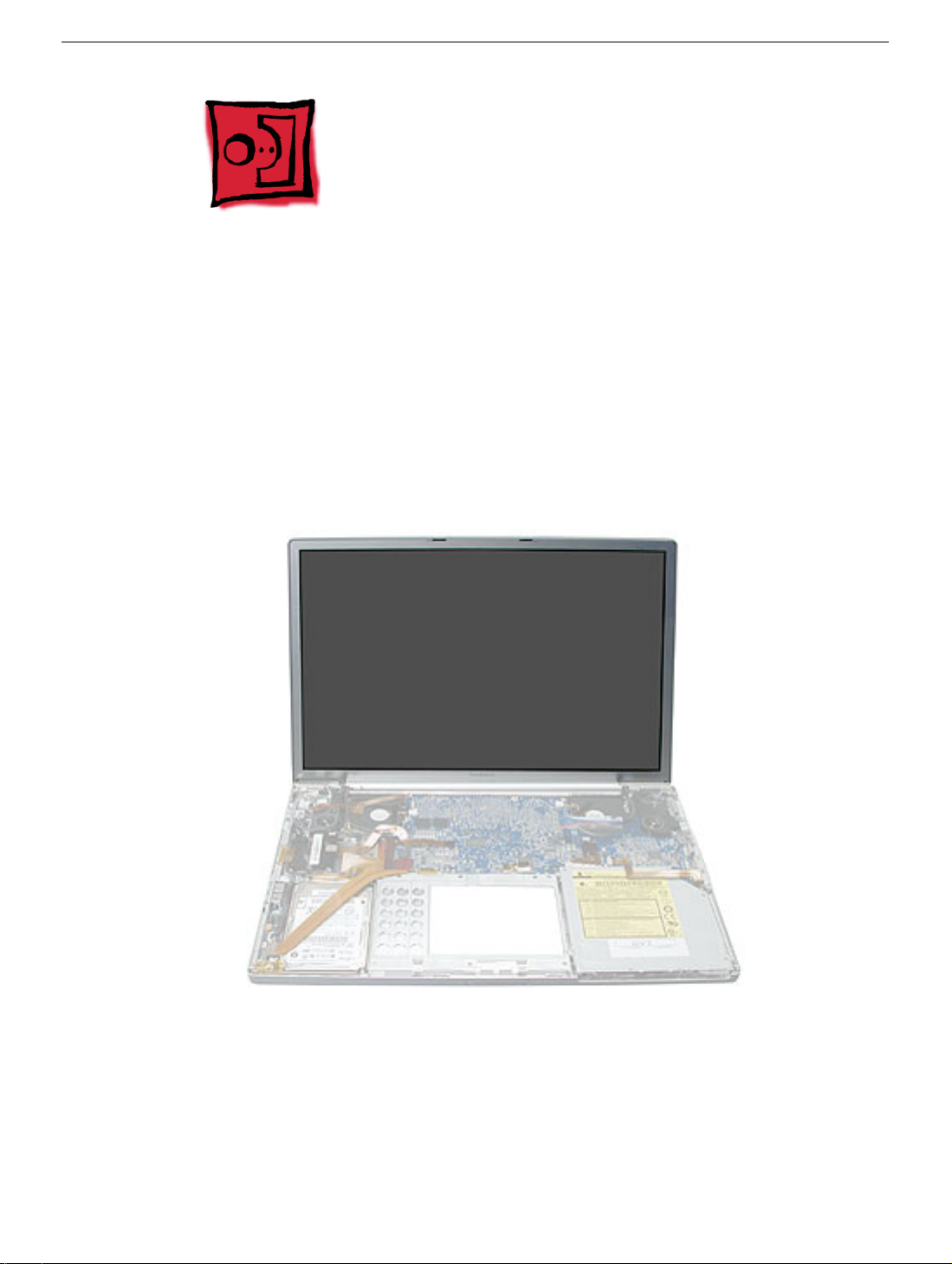
Display Panel Assembly
Tools
This procedure requires the following tools:
• Torx T6 screwdriver (magnetized)
• Black stick (or other nonconductive nylon or plastic flat-blade tool)
• 4 mm socket wrench (to install the pop-up spring torsion bar)
Part Location
Preliminary Steps
Before you begin, remove the following:
• Battery
• Top case
90 - PowerBook G4 (17-inch) Take Apart
Display Panel Assembly
Page 93
Procedure
Note: During these procedures, remove and reserve any Kapton tape for replacement, or
replace with new tape during reinstallation.
1. Carefully disconnect the cable connectors shown.
2. Pull out the coupling (joining the AirPort Extreme jumper and antenna cable) from the
channel in the side of the left speaker. Grasp the coupling (not the wires) at both ends
and pull to separate it at the middle.
Display Panel Assembly
PowerBook G4 (17-inch) Take Apart - 91
Page 94

3. Carefully disconnect the Bluetooth cable connector.
Important: During the following procedures, take care that the small parts and screws do
not fall inside the computer.
4. Remove the screws that hold the wire brackets at both sides of the clutch barrel.
92 - PowerBook G4 (17-inch) Take Apart
Display Panel Assembly
Page 95

5. Move the display to a 90-degree angle and remove the two screws for the end caps of
the clutch springs on each side.
Note: A 90-degree angle on the display helps to reduce the tension on the end
pieces.
6. Remove the two clutch cleat screws on each side of the clutch barrel.
Important: Before removing the last screw, support the display so that it does not fall over.
Display Panel Assembly
PowerBook G4 (17-inch) Take Apart - 93
Page 96

7. Lift off the display panel and clutch barrel assembly.
8. Remove the clutch spring end caps from both sides.
94 - PowerBook G4 (17-inch) Take Apart
Display Panel Assembly
Page 97

9. Remove the two screws and torsion bar on each side.
Display Panel Assembly
PowerBook G4 (17-inch) Take Apart - 95
Page 98

Replacement Procedure
1. To reinstall the display panel assembly, replace the end caps onto both clutch springs.
2. At the back corners of the bottom case assembly, push the pop-up spring pins all the
way back, on both sides.
96 - PowerBook G4 (17-inch) Take Apart
Display Panel Assembly
Page 99

3. On the clutch, push the limit stop feet all the way back, on both sides.
4. Lower the display panel assembly straight down onto the bottom case assembly.
5. Verify that the limit stop feet, fit into the holes in front of the pop-up spring pins, on
both sides.
Display Panel Assembly
PowerBook G4 (17-inch) Take Apart - 97
Page 100

6. Install and tighten the screws for the clutch cleats, on both sides.
7. Hold the display at a 90-degree angle and install the end cap screws on both sides.
98 - PowerBook G4 (17-inch) Take Apart
Display Panel Assembly
 Loading...