

Page 1

Final Cut Pro X
Logic Effects Reference
Page 2

Copyright © 2011 Apple Inc. All rights reserved.
Your rights to the software are governed by the
accompanying software license agreement. The owner or
authorized user of a valid copy of Final Cut Pro software
may reproduce this publication for the purpose of learning
to use such software. No part of this publication may be
reproduced or transmitted for commercial purposes, such
as selling copies of this publication or for providing paid
for support services.
The Apple logo is a trademark of Apple Inc., registered in
the U.S. and other countries. Use of the “keyboard” Apple
logo (Shift-Option-K) for commercial purposes without
the prior written consent of Apple may constitute
trademark infringement and unfair competition in violation
of federal and state laws.
Every effort hasbeen made to ensure thatthe information
in this manual is accurate. Apple is not responsible for
printing or clerical errors.
Note: Because Apple frequently releases new versions
and updates to its system software, applications, and
Internet sites,images shownin this manualmay be slightly
different from what you see on your screen.
Apple
1 Infinite Loop
Cupertino, CA 95014
408-996-1010
www.apple.com
Apple, the Apple logo, Final Cut, Final Cut Pro, Finder, and
Logic are trademarks of Apple Inc., registered in the U.S.
and other countries.
Other company and product names mentioned herein
are trademarks of their respective companies. Mention of
third-party products is for informational purposes only
and constitutes neither an endorsement nor a
recommendation. Apple assumes no responsibility with
regard to the performance or use of these products.
Page 3

Contents
An Introduction to Logic Effects for Final Cut Pro X5Preface
About the Logic Effects included with Final Cut Pro X5
Additional Resources7
Distortion Effects9Chapter 1
Bitcrusher10
Clip Distortion11
Distortion Effect12
Distortion II13
Overdrive13
Phase Distortion14
Ringshifter15
Echo Effects23Chapter 2
Delay Designer23
Modulation Delay42
Stereo Delay44
Tape Delay45
Equalizers47Chapter 3
AutoFilter47
Channel EQ53
Fat EQ56
Linear Phase EQ57
Levels Effects63Chapter 4
Types of Dynamics Processors63
Adaptive Limiter65
Compressor66
Enveloper70
Expander72
Gain Plug-in73
Limiter73
Multichannel Gain75
3
Page 4

Multipressor75
Noise Gate78
Spectral Gate81
Surround Compressor83
Modulation Effects89Chapter 5
Chorus Effect90
Ensemble Effect90
Flanger Effect92
Phaser Effect93
Scanner Vibrato Effect94
Tremolo Effect96
Spaces Effects97Chapter 6
Plates, Digital Reverb Effects, and Convolution Reverb98
PlatinumVerb99
Space Designer Convolution Reverb103Chapter 7
Getting to Know the Space Designer Interface104
Working with Space Designer’s Impulse Response Parameters105
Working with Space Designer’s Envelope and EQ Parameters109
Working with Space Designer’s Filter115
Working with Space Designer’s Global Parameters117
Automating Space Designer123
Specialized Effects and Utilities125Chapter 8
Correlation Meter125
Denoiser126
Direction Mixer128
Exciter131
MultiMeter132
Stereo Spread137
SubBass138
Test Oscillator140
Vocal Effects143Chapter 9
DeEsser143
Pitch Correction Effect145
Pitch Shifter II148
Vocal Transformer149
4 Contents
Page 5

An Introduction to Logic Effects for Final Cut Pro X
Final Cut Pro X comes bundled with an extensive range of Logic Effects, digital signal
processing (DSP) effects and processors that are used to color or tonally shape existing
audio recordings and audio sources—in real time. These will cover almost every audio
processing and manipulation need you will encounter in your day-to-day work.
The most common processing options include EQs, levels (dynamic processors),
modulations, distortions, spaces (reverbs), and echo (delays).
Further advanced features include precise signal meters and analyzers, noise reduction,
bass enhancement, and vocal effects.
As you can see, many of the included processors and utilities don’t really fall into the
“effects” category, but they may prove to be invaluable to your audio production needs.
All effects, processors, and utilities provide an intuitive interface that simplifies operation,
enabling you to work quickly. Outstanding audio quality is assured when needed, or—at
the other end of the spectrum—extreme processing is possible when you need to radically
alter your audio. All effects and processors are highly optimized for efficient CPU usage.
Preface
This preface covers the following:
• About the Logic Effects included with Final Cut Pro X (p. 5)
• Additional Resources (p. 7)
About the Logic Effects included with Final Cut Pro X
The Logic Effects included in Final Cut Pro X are also designed for specific uses. Given
these unique properties and uses, each application provides a custom collection of suitable
effects and utilities.
Included effectsEffect category
BitcrusherDistortion
Clip Distortion
Distortion Effect
Distortion II
5
Page 6

Included effectsEffect category
Overdrive
Phase Distortion
Ringshifter
Delay DesignerEcho
Modulation Delay
Stereo Delay
Tape Delay
AutoFilterEQ
Channel EQ
Fat EQ
Linear Phase EQ
Adaptive LimiterLevels
Compressor
Enveloper
Expander
Gain Plug-in
Limiter
Multichannel Gain
Multipressor
Noise Gate
Spectral Gate
Surround Compressor
Chorus EffectModulation
Ensemble Effect
Flanger Effect
Phaser Effect
Scanner Vibrato Effect
Tremolo Effect
PlatinumVerbSpaces
Space Designer Convolution Reverb
Correlation MeterSpecialized
Denoiser
Direction Mixer
Exciter
6 Preface An Introduction to Logic Effects for Final Cut Pro X
Page 7

Included effectsEffect category
MultiMeter
Stereo Spread
SubBass
Test Oscillator
DeEsserVocal
Pitch Correction Effect
Pitch Shifter II
Vocal Transformer
Additional Resources
In addition to the documentation that comes with Final Cut Pro, there are a variety of
other resources you can use to find out more.
Final Cut Pro Website
For general information and updates, as well as the latest news on Final Cut Pro, go to:
• http://www.apple.com/finalcutpro
Apple Service and Support Websites
For software updates and answers to the most frequently asked questions for all Apple
products, go to the general Apple Support webpage. You’ll also have access to product
specifications, reference documentation, and technical articles about Apple products and
products from other companies.
• http://www.apple.com/support
For software updates, documentation, discussion forums, and answers to the most
frequently asked questions for Final Cut Pro, go to:
• http://www.apple.com/support/finalcutpro
7Preface An Introduction to Logic Effects for Final Cut Pro X
Page 8

Page 9

Distortion Effects
1
You can use Distortion effects to recreate the sound of analog or digital distortion and
to radically transform your audio.
Distortion effects simulate the distortion created by vacuum tubes, transistors, or digital
circuits. Vacuum tubes were used in audio amplifiers before the development of digital
audio technology, and they are still used in musical instrument amplifiers today. When
overdriven, they produce a type of distortion that many people find musically pleasing,
and which has become a familiar part of the sound of rock and pop music. Analog tube
distortion adds a distinctive warmth and bite to the signal.
There are also distortion effects that intentionally cause clipping and digital distortion of
the signal. These can be used to modify vocal, music, and other clips to produce an
intense, unnatural effect, or to create sound effects.
Distortion effects include parameters for tone, which let you shape the way the distortion
alters the signal (often as a frequency-based filter), and for gain, which let you control
how much the distortion alters the output level of the signal.
Warning: When set to high output levels, distortion effects can damage your
hearing—and your speakers. When you adjust effect settings, it is recommended that
you lower the output level of the clip, and raise the level gradually when you are finished.
This chapter covers the following:
• Bitcrusher (p. 10)
• Clip Distortion (p. 11)
• Distortion Effect (p. 12)
• Distortion II (p. 13)
• Overdrive (p. 13)
• Phase Distortion (p. 14)
• Ringshifter (p. 15)
9
Page 10
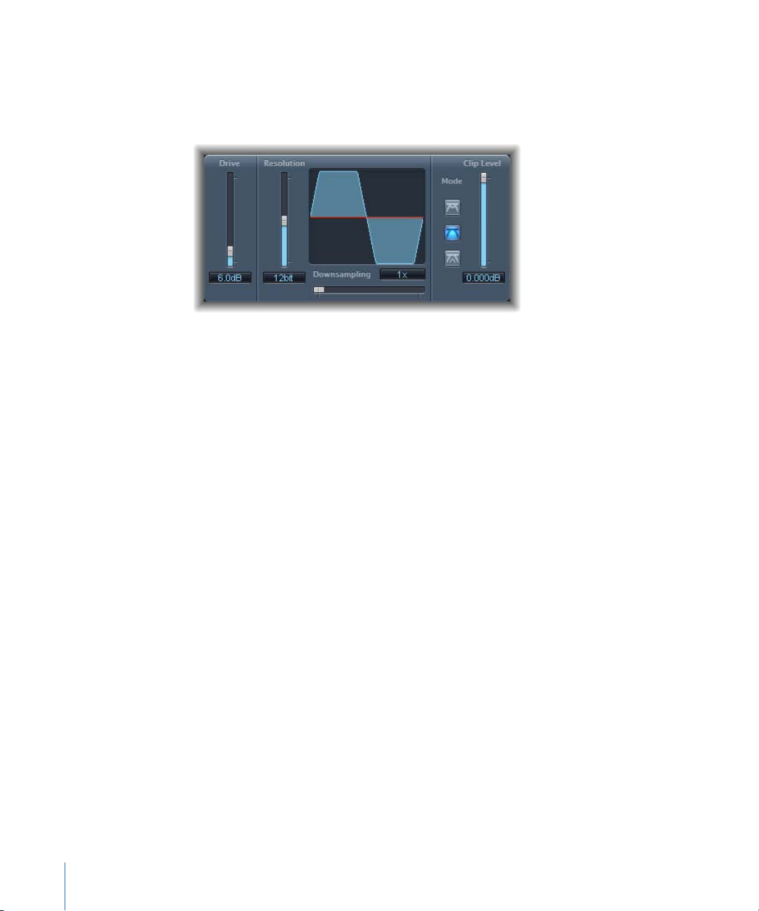
Bitcrusher
Bitcrusher is a low-resolution digital distortion effect. You can use it to emulate the sound
of early digital audio devices, to create artificial aliasing by dividing the sample rate, or
to distort signals until they are unrecognizable.
• Drive slider and field: Sets the amount of gain in decibels applied to the input signal.
Note: Raising the Drive level tends to increase the amount of clipping at the output of
the Bitcrusher as well.
• Resolution slider and field: Sets the bit rate (between 1 and 24 bits). This alters the
calculation precision of the process. Lowering the value increases the number of
sampling errors, generating more distortion. At extremely low bit rates, the amount of
distortion can be greater than the level of the usable signal.
• Waveform display: Shows the impact of parameters on the distortion process.
• Downsampling sliderand field: Reduces the sample rate. A value of 1 x leaves the signal
unchanged, a value of 2 x halves the sample rate, and a value of 10 x reduces the
sample rate to one-tenth of the original signal. (For example, if you set Downsampling
to 10 x , a 44.1 kHz signal is sampled at just 4.41 kHz.)
Note: Downsampling has no impact on the playback speed or pitch of the signal.
• Mode buttons: Set the distortion mode to Folded, Cut, or Displaced. Signal peaks that
exceed the clip level are processed.
Note: The Clip Level parameter has a significant impact on the behavior of all three
modes. This is reflected in the Waveform display, so try each mode button and adjust
the Clip Level slider to get a feel for how this works.
• Folded: The start and end levels of the clipped signal are unchanged, but the center
portion is effectively folded in half (halved in thelevel above the threshold), resulting
in a softer distortion.
• Cut: The signal is abruptly distorted when the clipping threshold is exceeded. Clipping
that occurs in most digital systems is closest to Cut mode.
10 Chapter 1 Distortion Effects
Page 11
• Displaced: The start, center, and end levels of the signal (above the threshold) are
offset, resulting in a distortion which is less severe as signal levels cross the threshold.
The center portion of the clipped signal is also softer than in Cut mode.
• Clip Level slider and field: Sets the point (below the clipping threshold of the clip) at
which the signal starts clipping.
• Mix slider and field (Extended Parameters area): Sets the balance between dry (original)
and wet (effect) signals.
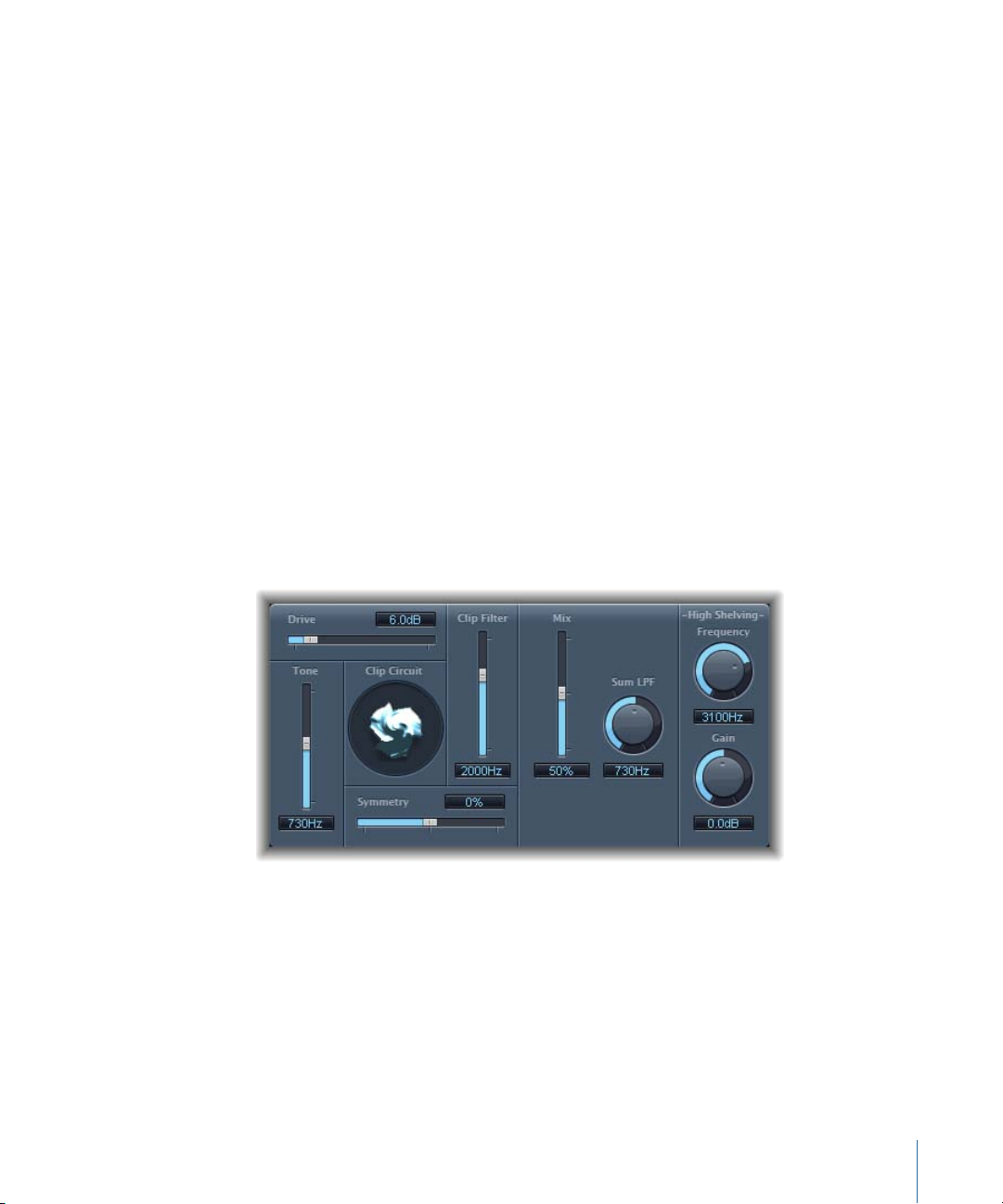
Clip Distortion
Clip Distortion is a nonlinear distortion effect that produces unpredictable spectra. It can
simulate warm, overdriven tube sounds and can also generate drastic distortions.
Clip Distortion features an unusual combination of serially connected filters. The incoming
signal is amplified by the Drive value, passes through a highpass filter, and is then
subjected to nonlinear distortion. Following the distortion, the signal passes through a
lowpass filter. The effect signal is then recombined with the original signal and this mixed
signal is sent through a further lowpass filter. All three filters have a slope of 6 dB/octave.
This unique combinationof filters allows for gaps inthe frequency spectra that can sound
quite good with this sort of nonlinear distortion.
• Drive slider and field: Sets the amount of gain applied to the input signal. After being
amplified by the Drive value, the signal passes through a highpass filter.
• Tone slider and field: Sets the cutoff frequency (in Hertz) of the highpass filter.
• Clip Circuit display: Shows the impact of all parameters, with the exception of the High
Shelving filter parameters.
• Symmetry sliderand field: Sets the amount of nonlinear (asymmetrical) distortion applied
to the signal.
• Clip Filter slider and field: Sets the cutoff frequency (in Hertz) of the first lowpass filter.
11Chapter 1 Distortion Effects
Page 12
• Mix slider and field: Sets the ratio between the effect (wet) signal and original (dry)
signals, following the Clip Filter.
• Sum LPF knob and field: Sets the cutoff frequency (in Hertz) of the lowpass filter. This
processes the mixed signal.
• (High Shelving) Frequency knob and field: Sets the frequency (in Hertz) of the high
shelving filter. If you set the High Shelving Frequency to around 12 kHz, you can use it
like the treble control on a stereo hi-fi amplifier. Unlike these types of treble controls,
however, you can boost or cut the signal by up to ±30 dB with the Gain parameter.
• (High Shelving)Gain knob andfield: Sets the amount of gain applied to the output signal.
• Input Gain field and slider (Extended Parameters area): Sets the amount of gain applied
to the input signal.
• Output Gainfield and slider(Extended Parameters area): Sets the amount of gain applied
to the output signal.
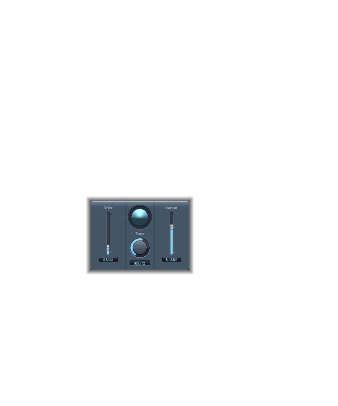
Distortion Effect
The Distortion effect simulates the lo-fi, dirty distortion generated by a bipolar transistor.
You can use it to simulate playing a musical instrument through a highly overdriven
amplifier, or to create unique distorted sounds.
• Drive slider and field: Sets the amount of saturation applied to the signal.
• Display: Shows the impact of parameters on the signal.
• Toneknob and field: Sets the frequency for the high cut filter. Filtering the harmonically
rich distorted signal produces a softer tone.
• Output sliderand field: Sets the output level. This allows you to compensatefor increases
in loudness caused by adding distortion.
12 Chapter 1 Distortion Effects
Page 13
Distortion II
Distortion II emulates the distortion circuit of a Hammond B3 organ. You can use it on
musical instruments to recreate this classic effect, or use it creatively when designing
new sounds.
• PreGain knob: Sets the amount of gain applied to the input signal.
• Drive knob: Sets the amount of saturation applied to the signal.
• Tone knob: Sets the frequency of the highpass filter. Filtering the harmonically rich
distorted signal produces a softer tone.
• Type pop-up menu: Choose the type of distortion you want to apply:
• Growl: Emulates a two-stage tube amplifier similar to the type found in a Leslie 122
speaker cabinet, which is often used with the Hammond B3 organ.
• Bity: Emulates the sound of a bluesy (overdriven) guitar amp.
• Nasty: Produces hard distortion, suitable for creating very aggressive sounds.
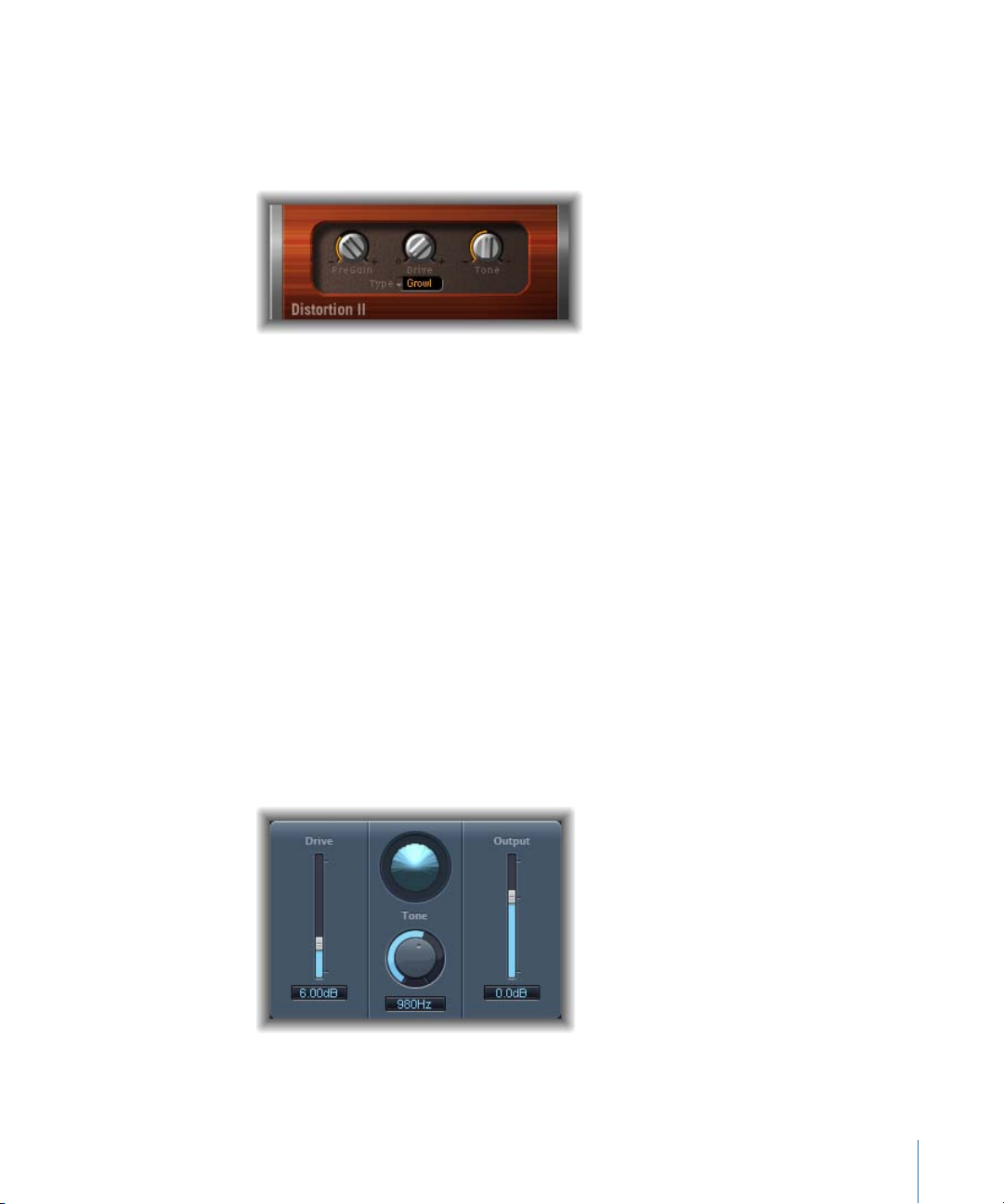
Overdrive
Overdrive emulates the distortion produced by a field effect transistor (FET), which is
commonly used in solid-state musical instrument amplifiers and hardware effects devices.
When saturated, FETs generate a warmer-sounding distortion than bipolar transistors,
such as those emulated by the Distortion effect.
• Drive slider and field: Sets the saturation amount for the simulated transistor.
13Chapter 1 Distortion Effects
Page 14
• Display: Shows the impact of parameters on the signal.
• Toneknob and field: Sets the frequency for the high cut filter. Filtering the harmonically
rich distorted signal produces a softer tone.
• Output sliderand field: Sets the output level. This allows you to compensatefor increases
in loudness caused by using Overdrive.
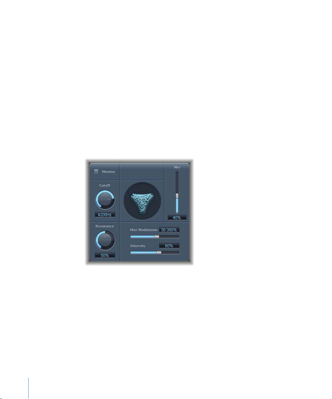
Phase Distortion
The Phase Distortion effect is based on a modulated delay line, similar to a chorus or
flanger effect (see Modulation Effects). Unlike these effects, however, the delay time is
not modulated by a low frequency oscillator (LFO), but rather by a lowpass-filtered version
of the input signal itself, using an internal sidechain. This means that the incoming signal
modulates its own phase position.
The input signal only passes the delay line and is not affected by any other process. The
Mix parameter blends the effect signal with the original signal.
• Monitor button: Enable to hear the input signal in isolation. Disable to hear the mixed
signal.
• Cutoff knob and field: Sets the (center) cutoff frequency of the lowpass filter.
• Resonance knob and field: Emphasizes frequencies surrounding the cutoff frequency.
• Display: Shows the impact of parameters on the signal.
• Mix slider and field: Adjusts the percentage of the effect signal mixed with the original
signal.
• Max Modulation slider and field: Sets the maximum delay time.
• Intensity slider and field: Sets the amount of modulation applied to the signal.
14 Chapter 1 Distortion Effects
Page 15

• Phase Reverse checkbox (Extended Parametersarea): Enable to reduce the delay time on
the right channel when input signals that exceed the cutoff frequency are received.
Available only for stereo instances of the Phase Distortion effect.
Ringshifter
The Ringshifter effect combines a ring modulator with a frequency shifter effect. Both
effects were popular during the 1970s, and are currently experiencing something of a
renaissance.
The ring modulator modulates the amplitude of the input signal using either the internal
oscillator or a side-chain signal. The frequency spectrum of the resulting effect signal
equals the sum and difference of the frequency content in the two original signals. Its
sound is often described as metallic or clangorous. Thering modulator was used extensively
on jazz rock and fusion records in the early 1970s.
The frequency shifter moves the frequency content of the input signal by a fixed amount
and, in doing so, alters the frequency relationship of the original harmonics. The resulting
sounds range from sweet and spacious phasing effects to strange robotic timbres.
Note: Frequency shifting should not be confused with pitch shifting. Pitch shifting
transposes the original signal, leaving its harmonic frequency relationship intact.
15Chapter 1 Distortion Effects
Page 16
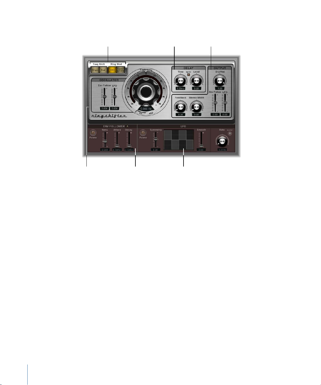
Getting to Know the Ringshifter Interface
Output parametersDelay parameters Mode buttons
LFO parametersEnvelope follower
parameters
Oscillator parameters
The Ringshifter interface consists of six main sections.
• Mode buttons: Determine whether the Ringshifter operates as frequency shifter or ring
modulator. See Setting the Ringshifter Mode.
• Oscillator parameters: Use these to configure the internal sine wave oscillator, which
modulates the amplitude of the input signal—in both frequency shifter modes and
the ring modulator OSC mode. See Using the Ringshifter’s Oscillator.
• Delay parameters: Use these to delay the effect signal. See Using the Ringshifter’s Delay.
• Envelope follower parameters: The oscillator frequency and output signal can be
modulated with an envelope follower. See Modulating theRingshifter with the Envelope
Follower.
• LFO parameters: The oscillator frequency and output signal can be modulated with an
LFO. See Modulating the Ringshifter with the LFO.
• Output parameters: The output section of the Ringshifter includes a feedback loop and
controls to set the stereo width and amount of the dry and wet signals. See Controlling
the Ringshifter Output Parameters.
16 Chapter 1 Distortion Effects
Page 17
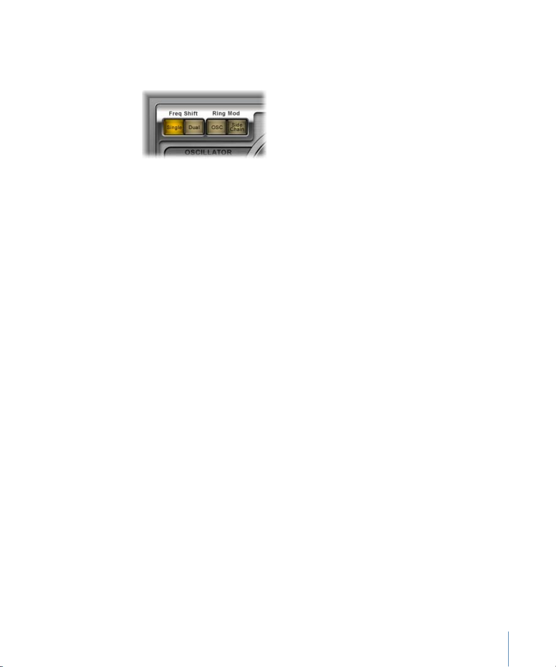
Setting the Ringshifter Mode
The four mode buttons determine whether the Ringshifter operates as a frequency shifter
or as a ring modulator.
• Single (Frequency Shifter) button: The frequency shifter generates a single, shifted effect
signal. The oscillator Frequency control determines whether the signal is shifted up
(positive value) or down (negative value).
• Dual (Frequency Shifter) button: The frequency shifting process produces one shifted
effect signal for each stereo channel—one is shifted up, the other is shifted down. The
oscillator Frequency control determines the shift direction in the left versus the right
channel.
• OSC (Ring Modulator) button: The ring modulator uses the internal sine wave oscillator
to modulate the input signal.
• Side Chain (Ring Modulator) button: The ring modulator modulates the amplitude of
the input signal with the audio signal assigned via the side-chain input. The sine wave
oscillator is switched off, and the Frequency controls are not accessible when Side
Chain mode is active.
Using the Ringshifter’s Oscillator
In both frequency shifter modes and the ring modulator OSC mode, the internal sine
wave oscillator is used to modulate the amplitude of the input signal.
• In the frequency shifter modes, the Frequency parameter controls the amount of
frequency shifting (up and/or down) applied to the input signal.
17Chapter 1 Distortion Effects
Page 18
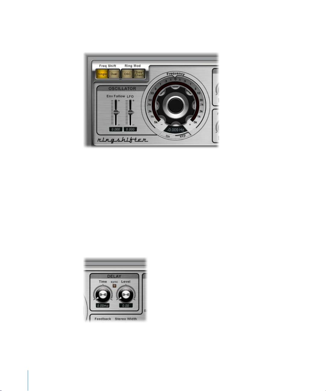
• In the ring modulator OSC mode, the Frequency parameter controls the frequency
content (timbre) of the resulting effect. This timbre can range from subtle tremolo
effects to clangorous metallic sounds.
• Frequency control: Sets the frequency of the sine oscillator.
• Lin(ear) and Exp(onential) buttons: Switch the scaling of the Frequency control:
• Exp(onential): Exponential scaling offers extremely small increments around the
0 point, which is useful for programming slow-moving phasing and tremolo effects.
• Lin(ear): Linear scaling resolution is even across the entire control range.
• Env Follow slider and field: Determines the impact of incoming signal levels on the
oscillator modulation depth.
• LFO slider and field: Determines the amount of oscillator modulation by the LFO.
Using the Ringshifter’s Delay
The effect signal is routed through a delay, following the oscillator.
• Time knob and field: Sets the delay time. This is in Hz when running freely, or in note
values (including triplet and dotted notes) when the Sync button is active.
18 Chapter 1 Distortion Effects
Page 19
• Sync button: Synchronizes the delay to the project tempo. You can choose musical
note values with the Time knob.
• Level knob and field: Sets the level of the delay added to the ring-modulated or
frequency-shifted signal. A Level value of 0 passes the effect signal directly to the output
(bypass).
Modulating the Ringshifter with the Envelope Follower
The oscillator Frequency and Dry/Wet parameters can be modulated with the internal
envelope follower—and the LFO (see Modulating the Ringshifter with the LFO). The
oscillator frequency even allows modulation through the 0 Hz point, thus changing the
oscillation direction.
The envelope follower analyzes the amplitude (volume) of the input signal and uses this
to create a continuously changing control signal—a dynamic volume envelope of the
input signal. This control signal can be used for modulation purposes.
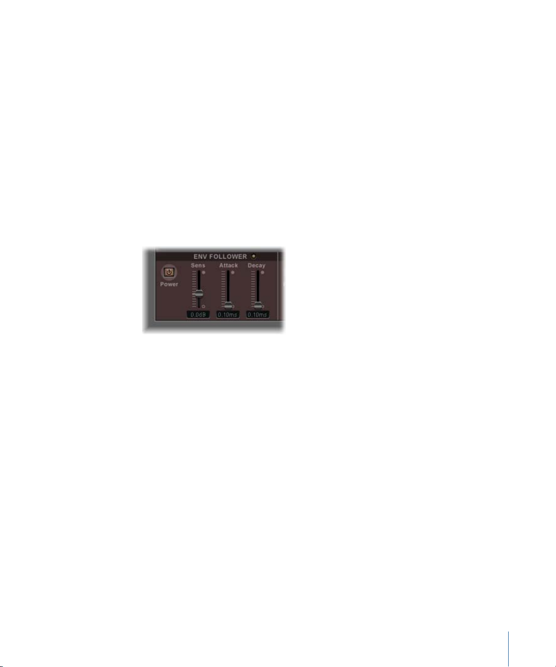
• Power button: Turns the envelope follower on or off and enables the following
parameters.
• Sens(itivity) slider and field: Determines how responsive the envelope follower is to the
input signal. At lower settings, the envelope follower reacts only to the most dominant
signal peaks. At higher settings, the envelope follower tracks the signal more closely,
but may react less dynamically.
• Attack slider and field: Sets the response time of the envelope follower.
• Decay slider and field: Controls the time it takes the envelope follower to return from
a higher to a lower value.
19Chapter 1 Distortion Effects
Page 20
Modulating the Ringshifter with the LFO
The oscillator Frequency and Dry/Wet parameters can be modulated with the LFO—and
the envelope follower (see Modulating the Ringshifter with the Envelope Follower). The
oscillator frequency even allows modulation through the 0 Hz point, thus changing the
oscillation direction. The LFO produces continuous, cycled control signals.
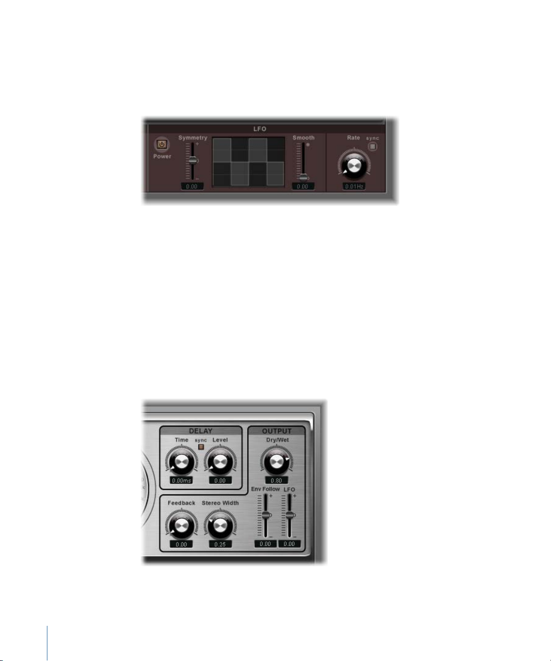
• Power button: Turns the LFO on or off and enables the following parameters.
• Symmetry and Smooth slidersand fields: These controls, on either side of the Waveform
display, change the shape of the LFO waveform.
• Waveform display: The LFO waveform display provides visual feedback about the
waveform shape.
• Rate knob and field: Sets the (waveform cycle) speed of the LFO.
• Sync button: Synchronizes the LFO cycles (LFO rate) with the project tempo, using
musical note values.
Controlling the Ringshifter Output Parameters
The output parameters are used to set the balance between the effect and input signals
and also to set the width and feedback of the Ringshifter.
• Dry/Wet knob and field: Sets the mix ratio of the dry input signal and the wet effect
signal.
20 Chapter 1 Distortion Effects
Page 21

• Feedback knob and field: Sets the amount of the signal that is routed back to the effect
input. Feedback adds an edge to the Ringshifter sound and is useful for a variety of
special effects. It produces a rich phasing sound when used in combination with a slow
oscillator sweep. Comb filtering effects are created by using high Feedback settings
with a short delay time (less than 10 ms). Use of longer delay times, in conjunction with
high Feedback settings, creates continuously rising and falling frequency shift effects.
• Stereo Width knob and field: Determines the breadth of the effect signal in the stereo
field. Stereo Width affects only the effect signal of the Ringshifter, not the dry input
signal.
• Env Follower sliderand field: Determines the amount of Dry/Wet parameter modulation
by the input signal level.
• LFO slider and field: Sets the LFO modulation depth of the Dry/Wet parameter.
21Chapter 1 Distortion Effects
Page 22

Page 23

Echo Effects
2
Echo effects store the input signal—and hold it for a short time—before sending it to
the effect input or output.
The held, and delayed, signal is repeated after a given time period, creating a repeating
echo effect, or delay. Each subsequent repeat is a little quieter than the previous one.
Most delays also allow you to feed a percentage of the delayed signal back to the input.
This can result in a subtle, chorus-like effect or cascading, chaotic audio output.
The delay time can often be synchronized to the project tempo by matching the grid
resolution of the project, usually in note values or milliseconds.
You can use delays to double individual sounds to resemble a group of instruments
playing the same melody, to create echo effects, to place the sound in a large “space,”
to generate rhythmic effects, or to enhance the stereo position of an audio clip.
Echo effects are generally used as individual audio clip effects. They are rarely used on
an overall mix, unless you’re trying to achieve an unusual effect.
This chapter covers the following:
• Delay Designer (p. 23)
• Modulation Delay (p. 42)
• Stereo Delay (p. 44)
• Tape Delay (p. 45)
Delay Designer
Delay Designer is a multitap delay. Unlike traditional delay units that offer only one or
two delays (or taps) that may or may not be fed back into the circuit, Delay Designer
provides up to 26 individual taps. These taps are all fed from the source signal and can
be freely edited to create delay effects that have never been heard before.
Delay Designer provides control over the following aspects of each tap:
• Level and pan position
23
Page 24
• Highpass and lowpass filtering
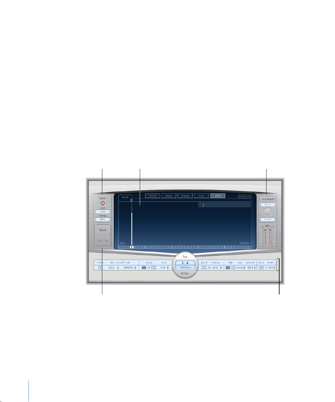
Sync section
Tap parameter barTap pads
Master section
Main display
• Pitch transposition (up or down)
Further effect-wide parameters include synchronization, quantization, and feedback.
As the name implies, Delay Designer offers significant sound design potential. You can
use it for everything from a basic echo effect to an audio pattern sequencer. You can
create complex, evolving, moving rhythms by synchronizing the placement of taps. This
leads to further musical possibilities when coupled with judicious use of transposition
and filtering. Alternatively, you can set up numerous taps as repeats of other taps, much
as you would use the feedback control of a simple delay, but with individual control over
each repeat.
You can use Delay Designer with mono, stereo, or surround clips. See Working with
Delay Designer in Surround for details on using it in surround.
Getting to Know the Delay Designer Interface
The Delay Designer interface consists of five main sections:
• Main display: Provides a graphic representation of all taps. You can see, and edit, the
parameters of each tap in this area. See Getting to Know Delay Designer’s Main Display.
• Tapparameter bar: Offers a numeric overview of the current parameter settings for the
selected tap. You can view and edit the parameters of each tap in this area. See Editing
Taps in Delay Designer’s Tap Parameter Bar.
• Tap pads: You can use these two pads to create taps in Delay Designer. See Creating
Taps in Delay Designer.
24 Chapter 2 Echo Effects
Page 25
• Sync section: This is used for syncing tempo in Logic Pro and is disabled for use with
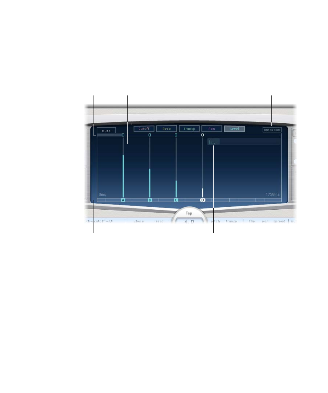
View buttonsToggle buttons Autozoom button
Overview display
Tap display
Identification bar
Final Cut Pro.
• Master section: This area contains the global Mix and Feedback parameters. See Using
Delay Designer’s Master Section.
Getting to Know Delay Designer’s Main Display
Delay Designer’s main display is used to view and edit tap parameters. You can freely
determine the parameter shown, and quickly zoom or navigate through all taps.
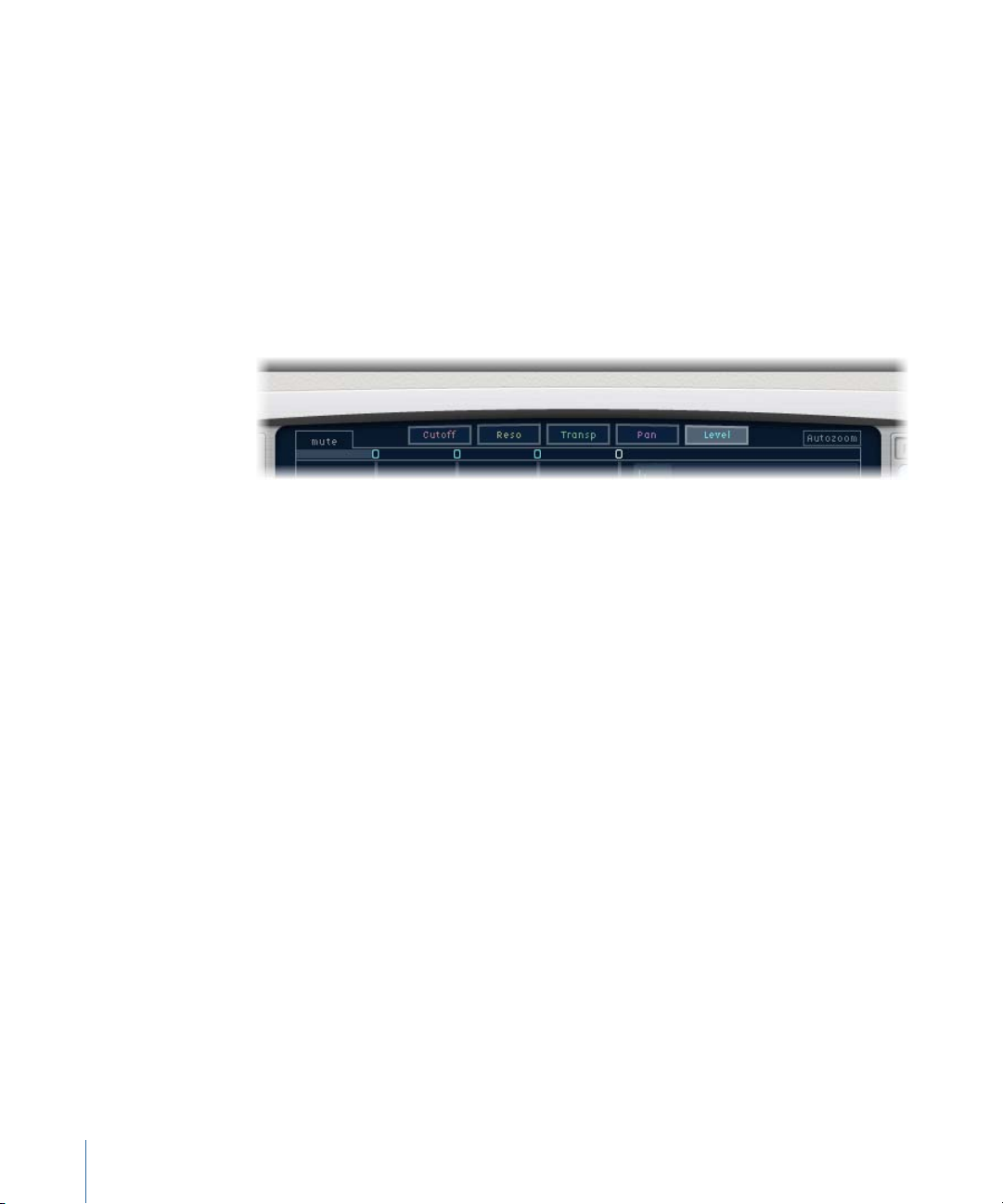
• View buttons: Determine the parameter or parameters represented in the Tap display.
See Using Delay Designer’s View Buttons.
• Autozoom button: Zooms the Tap display out, making all taps visible. Turn Autozoom
off if you want to zoom the display in (by dragging vertically on the Overview display)
to view specific taps.
• Overview display: Shows all taps in the time range. See Zooming and Navigating
Delay Designer’s Tap Display.
• Toggle buttons: Click to enable or disable the parameters of a particular tap. The
parameter being toggled is chosen with the view buttons. The label at the left of the
toggle bar always indicates the parameter being toggled. For more information, see
Using Delay Designer’s Tap Toggle Buttons.
25Chapter 2 Echo Effects
Page 26
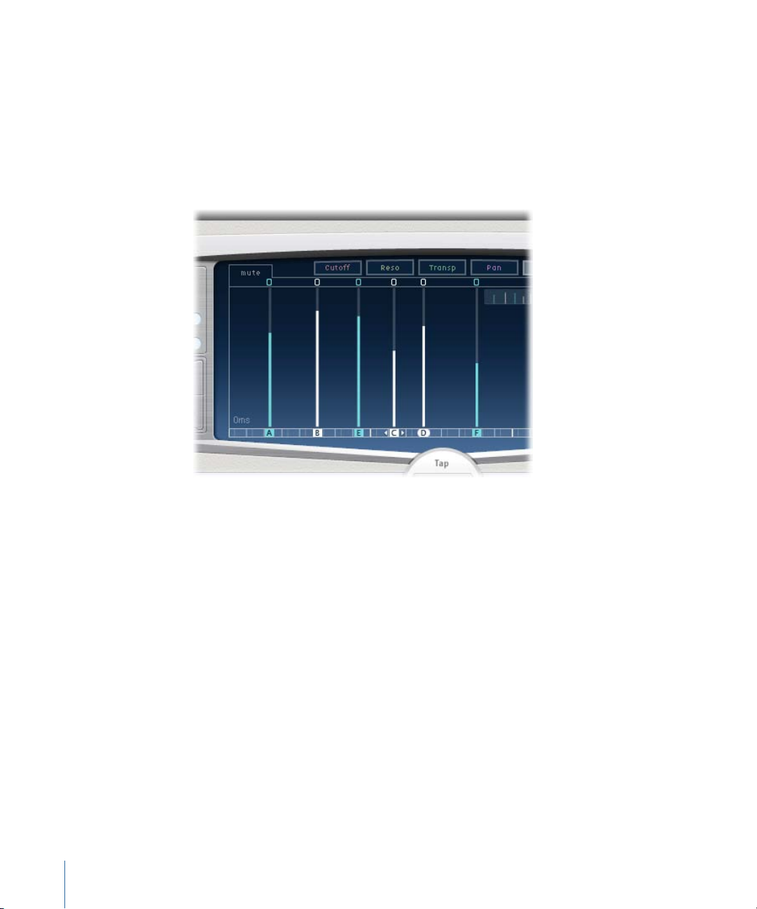
• Tap display: Represents each tap as a shaded line. Each tap contains a bright bar (or
dot for stereo panning) that indicates the value of the parameter. You can directly edit
tap parameters in the Tap display area. For more details, see Editing Parameters in
Delay Designer’s Tap Display.
• Identification bar: Shows an identification letter for each tap. It also serves as a time
position indicator for each tap. You may freely move taps backward or forward in time
along this bar/timeline. See Moving and Deleting Taps in Delay Designer.
Using Delay Designer’s View Buttons
The view buttons determine which parameter is represented in Delay Designer’s Tap
display.
• Cutoff button: Shows the highpass and lowpass filter cutoff frequencies of taps.
• Reso(nance) button: Shows the filter resonance value of each tap.
• Transp(ose) button: Shows the pitch transposition of each tap.
• Pan button: Shows the pan parameter of each tap.
• For mono to stereo channels, each tap contains a line showing its pan position.
• For stereo to stereo channels, each tap contains a dot showing its stereo balance. A
line extending outwards from the dot indicates the tap’s stereo spread.
• For surround channels, each tap contains a line representing its surround angle (for
details, see Working with Delay Designer in Surround).
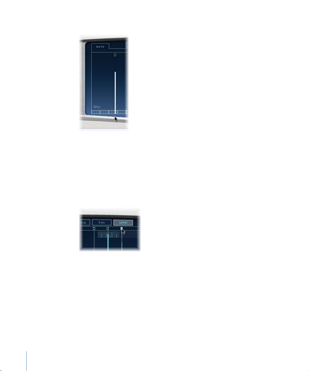
• Level button: Shows the relative volume level of each tap.
Tip: You can temporarily switch the Tap display to Level view from one of the other
view modes by pressing Command-Option.
26 Chapter 2 Echo Effects
Page 27
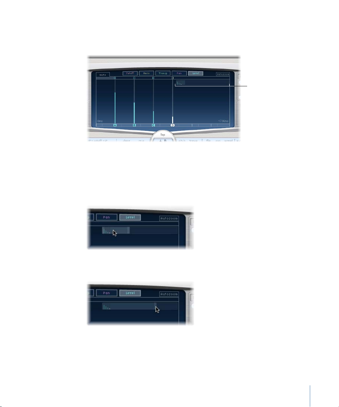
Zooming and Navigating Delay Designer’s Tap Display
Overview display
You can use Delay Designer’s Overview display to zoom and to navigate the Tap display
area.
Tip: If the Overview display is hidden behind a tap, you can move it to the foreground
by holding down Shift.
To zoom the Tap display
Do one of the following:
Vertically drag the highlighted section (the bright rectangle) of the Overview display.
µ
Horizontally drag the highlighted bars—to the left or right of the bright rectangle—in
µ
the Overview display.
Note: The Autozoom button needs to be disabled when manually zooming with the
Overview display. When you zoom in on a small group of taps, the Overview display
continues to show all taps. The area shown in the Tap display is indicated by the bright
rectangle in the Overview display.
27Chapter 2 Echo Effects
Page 28
To move to different sections of the Tap display
Horizontally drag the (middle of the) bright rectangle in the Overview display.
µ
The zoomed view in the Tap display updates as you drag.
Creating Taps in Delay Designer
You can create new delay taps in three different ways: by using the Tap pads, by creating
them in the Identification bar, or by copying existing taps.
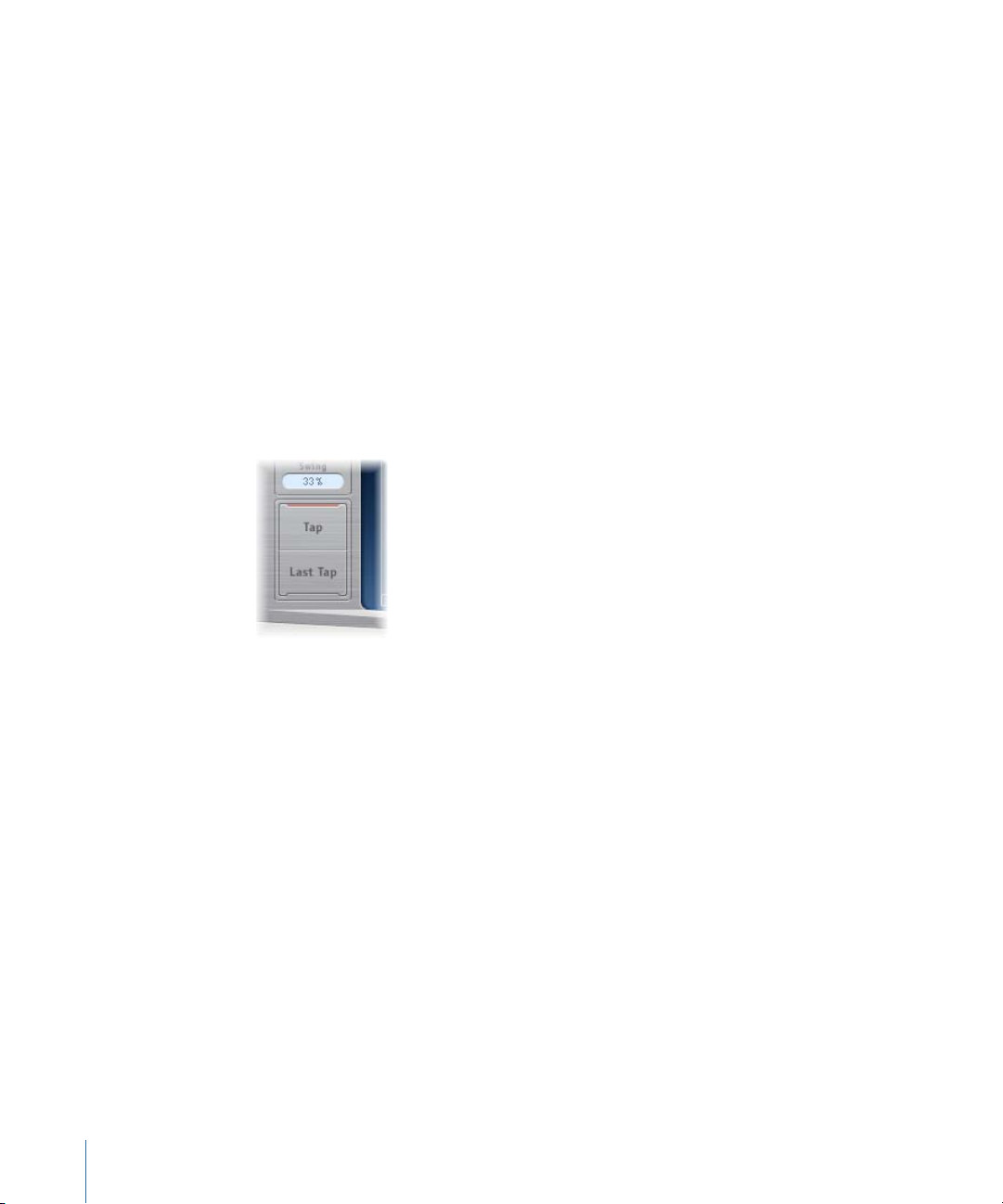
To create taps with the Tap pad
1 Click the upper pad (Start).
Note: Whenever you click the Start pad, it automatically erases all existing taps. Given
this behavior, after you have created your initial taps, you will want to create subsequent
taps by clicking in the Identification bar.
The upper pad label changes to Tap, and a red tap recording bar appears in the strip
below the view buttons.
2 Click the Tap button to begin recording new taps.
3 Click the Tap button to create new taps. These are created at the exact moments in time
of each click, adopting the rhythm of your click pattern.
4 To finish creating taps, click the Last Tap button.
This adds the final tap, ending tap recording, and assigning the last tap as the feedback
tap (for an explanation of the feedback tap, see Using Delay Designer’s Master Section).
Note: If you do not click the Last Tap button, tap recording automatically stops after
10 seconds or when the 26th tap is created, whichever comes first.
28 Chapter 2 Echo Effects
Page 29
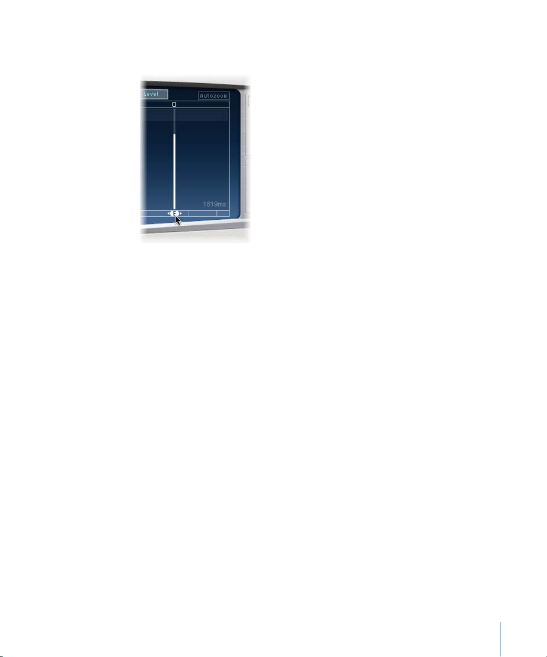
To create taps in the Identification bar
Click at the appropriate position.
µ
To copy taps in the Identification bar
Option-drag a selection of one or more taps to the appropriate position.
µ
The delay time of copied taps is set to the drag position.
Delay Designer Tap Creation Suggestions
The fastest way to create multiple taps is to use the Tap pads. If you have a specific rhythm
in mind, you might find it easier to tap out your rhythm on dedicated hardware controller
buttons, instead of using mouse clicks. If you have a MIDI controller, you can assign the
Tap pads to buttons on your device. For information about assigning controllers, see the
Control Surfaces Support manual.
Note: Whenever you click the Start Tap pad, it automatically erases all existing taps. Given
this behavior, after you create your initial taps you will want to create subsequent taps
by clicking in the Identification bar.
After a tap has been created, you can freely adjust its position, or you can remove it if it
was created accidentally. For details, see Moving and Deleting Taps in Delay Designer.
Identifying Taps in Delay Designer
Taps are assigned letters, based on their order of creation. The first tap to be created is
assigned as Tap A, the second tap is assigned as Tap B, and so on. Once assigned, each
tap is always identified by the same letter, even when moved in time, and therefore
reordered. For example, if you initially create three taps they will be named Tap A, Tap B,
and Tap C. If you then change the delay time of Tap B so that it precedes Tap A, it will
still be called Tap B.
29Chapter 2 Echo Effects
Page 30
The Identification bar shows the letter of each visible tap. The Tap Delay field of the Tap
parameter bar displays the letter of the currently selected tap, or the letter of the tap
being edited when multiple taps are selected (for details, see Selecting Taps in
Delay Designer).
Selecting Taps in Delay Designer
There will always be at least one selected tap. You can easily distinguish selected taps by
color—the toggle bar icons and the Identification bar letters of selected taps are white.
To select a tap
Do one of the following:
Click a tap in the Tap display.
µ
Click the appropriate tap letter in the Identification bar.
µ
Click one of the arrows to the left of the Tap name to select the next or previous tap.
µ
30 Chapter 2 Echo Effects
Page 31

Open the pop-up menu to the right of the Tap name, and choose the appropriate tap
µ
letter.
To select multiple taps
Do one of the following:
Drag across the background of the Tap display to select multiple taps.
µ
Shift-click specific taps in the Tap display to select multiple nonadjacent taps.
µ
Moving and Deleting Taps in Delay Designer
You can move a tap backward or forward in time, or completely remove it.
Note: When you move a tap, you are actually editing its delay time.
To move a selected tap in time
Select the tap in the Identification bar, and drag it to the left to go forward in time, or to
µ
the right to go backward in time.
This method also works when more than one tap is selected.
Note: Editing the Delay Time parameter in the Tap Delay field of the Tap parameter bar
also moves a tap in time. For more details about the Tap Delay field and editing taps, see
Editing Taps in Delay Designer’s Tap Parameter Bar.
To delete a tap
Do one of the following:
Select it and press the Delete or Backspace key.
µ
31Chapter 2 Echo Effects
Page 32
Select a tap letter in the Identification bar and drag it downward, out of the Tap display.
µ
This method also works when more than one tap is selected.
To delete all selected taps
Control-click (or right-click) a tap, and choose “Delete tap(s)” from the shortcut menu.
µ
Using Delay Designer’s Tap Toggle Buttons
Each tap has its own toggle button in the Toggle bar. These buttons offer you a quick
way to graphically activate and deactivate parameters. The specific parameter being
toggled by the toggle buttons depends on the current view button selection:
• Cutoff view: Toggle buttons turn the filter on or off.
• Reso view: Toggle buttons switch the filter slope between 6 dB and 12 dB.
• Pitch view: Toggle buttons switch pitch transposition on or off.
• Pan view: Toggle buttons switch between the Flip modes.
• Level view: Toggle buttons mute or unmute the tap.
To temporarily switch the mute state of taps
Command-Option-click a toggle button, regardless of the current view mode.
µ
When you release the Command and Option keys, the toggle buttons return to their
standard functionality in the active View mode.
32 Chapter 2 Echo Effects
Page 33
Note: The first time you edit a filter or pitch transpose parameter, the respective module
automatically turns on. This saves you the effort of manually turning on the filter or pitch
transposition module before editing. After you manually turn either of these modules
off, however, you need to manually switch it back on.
Editing Parameters in Delay Designer’s Tap Display
You can graphically edit any tap parameter that is represented as a vertical line in
Delay Designer’s Tap display. The Tap display is ideal if you want to edit the parameters
of one tap relative to other taps, or when you need to edit multiple taps simultaneously.
To edit a tap parameter in the Tap display
1 Click the view button of the parameter you want to edit.
2 Vertically drag the bright line of the tap you wish to edit (or one of the selected taps, if
multiple taps are selected).
If you have chosen multiple taps, the values of all selected taps will be changed relative
to each other.
Note: The method outlined above is slightly different for the Filter Cutoff and Pan
parameters. See Editing Filter Cutoff in Delay Designer’s Tap Display and Editing Pan in
Delay Designer’s Tap Display.
To set the values of multiple taps
Command-drag horizontally and vertically across several taps in the Tap display.
µ
33Chapter 2 Echo Effects
Page 34
Parameter values change to match the mouse position as you drag across the taps.
Command-dragging across several taps allows you to draw value curves, much like using
a pencil to create a curved line on a piece of paper.
Aligning Delay Designer Tap Values
You can use Delay Designer’s Tap display to graphically align tap parameter values that
are represented as vertical lines.
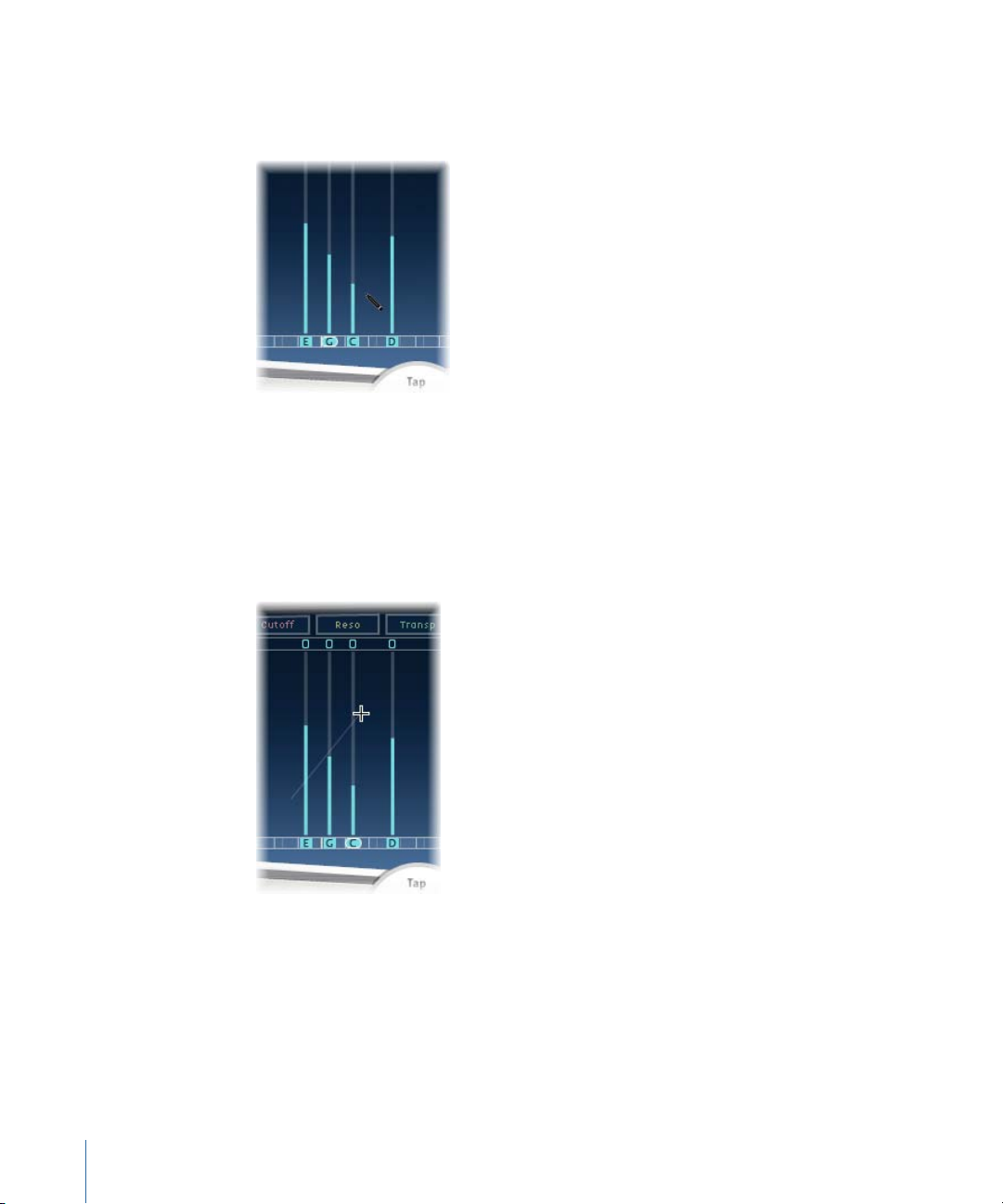
To align the values of several taps
1 Command-click in the Tap display, and move the pointer while holding down the
Command key. This will result in a line trailing behind the pointer.
2 Click the appropriate position to mark the end point of the line.
34 Chapter 2 Echo Effects
Page 35
The values of taps that fall between the start and end points are aligned along the line.
Editing Filter Cutoff in Delay Designer’s Tap Display
Whereas the steps outlined in Editing Parameters in Delay Designer’s Tap Display apply
to most graphically editable parameters, the Cutoff and Pan parameters work in a slightly
different fashion.
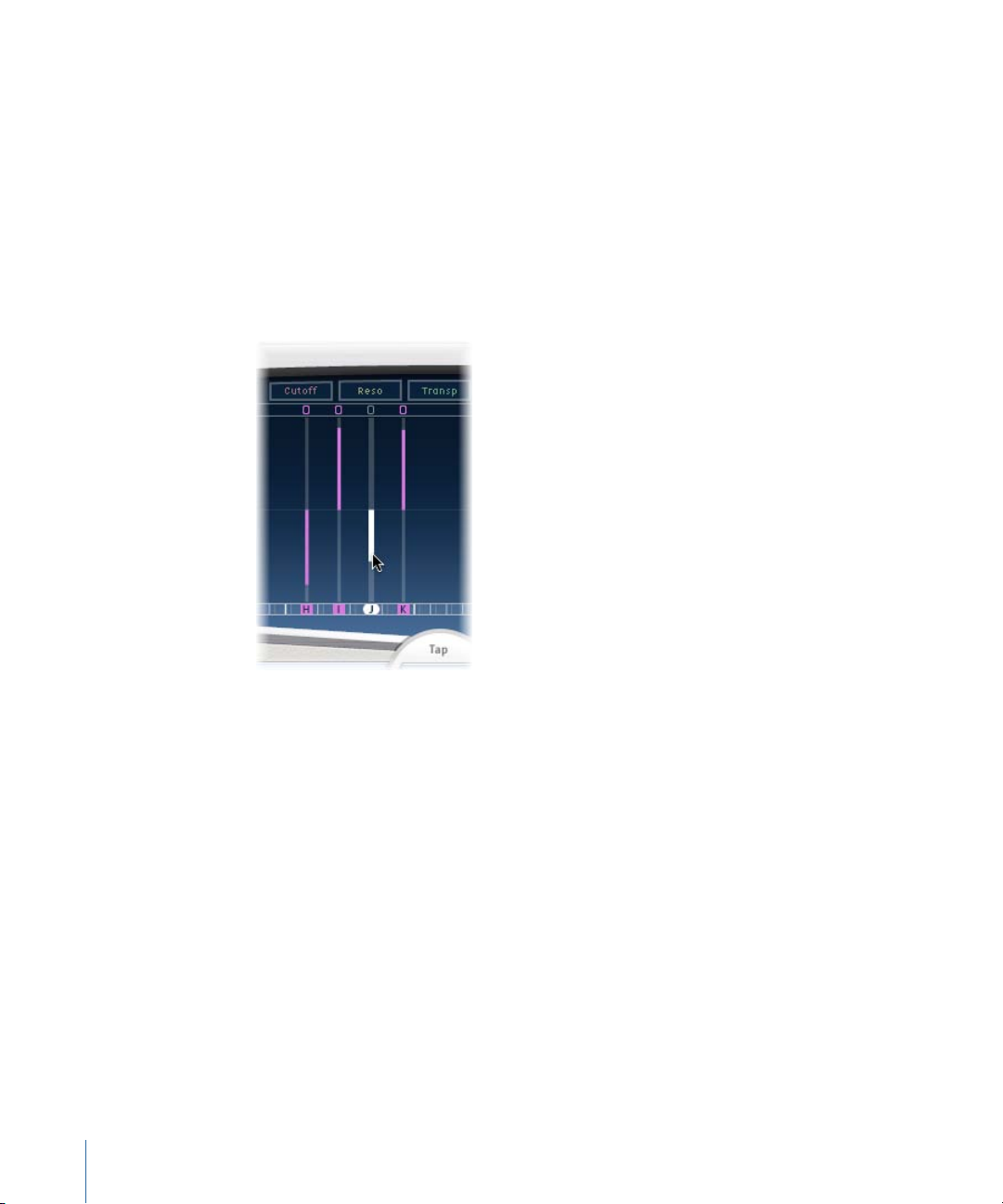
In Cutoff view, each tap actually shows two parameters: highpass and lowpass filter cutoff
frequency. The filter cutoff values can be adjusted independently by dragging the specific
cutoff frequency line—the upper line is lowpass and the lower line is highpass—or both
cutoff frequencies can be adjusted by dragging between them.
When the highpass filter cutoff frequency value is lower than that of the lowpass cutoff
frequency, only one line is shown. This line represents the frequency band that passes
through the filters—in other words, the filters act as a bandpass filter. In this configuration,
the two filters operate serially, meaning that the tap passes through one filter first, then
the other.
35Chapter 2 Echo Effects
Page 36
If the highpass filter’s cutoff frequency value is above that of the lowpass filter cutoff
frequency, the filter switches from serial operation to parallel operation, meaning that
the tap passes through both filters simultaneously. In this case, the space between the
two cutoff frequencies represents the frequency band being rejected—in other words,
the filters act as a band-rejection filter.
Editing Pan in Delay Designer’s Tap Display
The way the Pan parameter is represented in the Pan view is entirely dependent on the
input channel configuration—mono to stereo, stereo to stereo, or surround.
Note: Pan is not available in mono configurations.
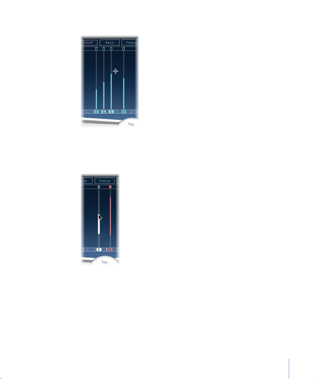
In mono input/stereo output configurations, all taps are initially panned to the center.
To edit the pan position, drag vertically from the center of the tap in the direction you
wish topan the tap, or taps. A white line extends outward from the center in the direction
you have dragged, reflecting the pan position of the tap, or taps.
36 Chapter 2 Echo Effects
Page 37
Lines above the center position indicate pans to the left, and lines below the center
position denote pans to the right. Left (blue) and right (green) channels are easily
identified.
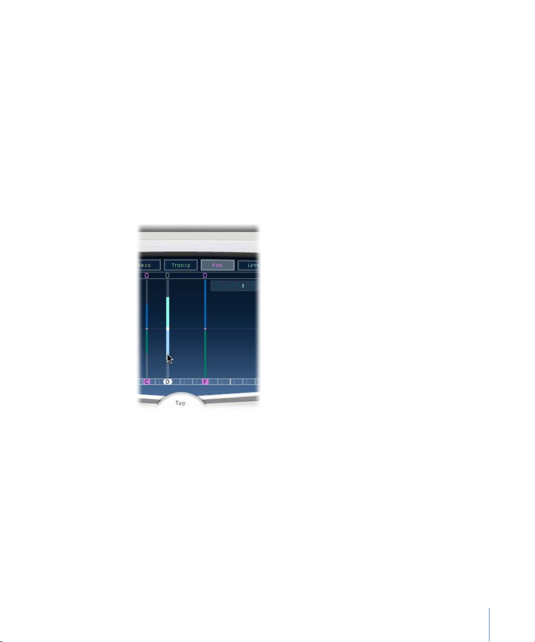
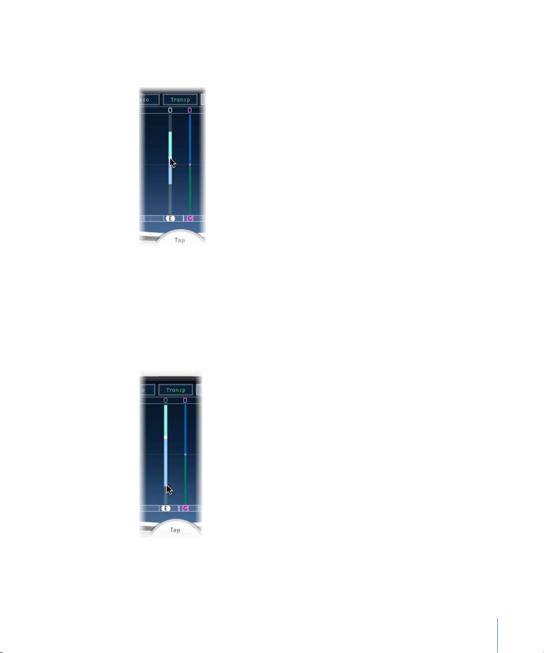
In stereo input/stereo output configurations, the Pan parameter adjusts the stereo balance,
not the position of the tap in the stereo field. The Pan parameter appears as a dot on the
tap, which represents stereo balance. Drag the dot up or down the tap to adjust the
stereo balance.
By default, stereo spread is set to 100%. To adjust this, drag either side of the dot. As you
do so, the width of the line extending outwards from the dot changes. Keep an eye on
the Spread parameter in the Tap parameter bar while you are adjusting.
In surround configurations, the bright line represents the surround angle. For more
information, see Working with Delay Designer in Surround.
37Chapter 2 Echo Effects
Page 38
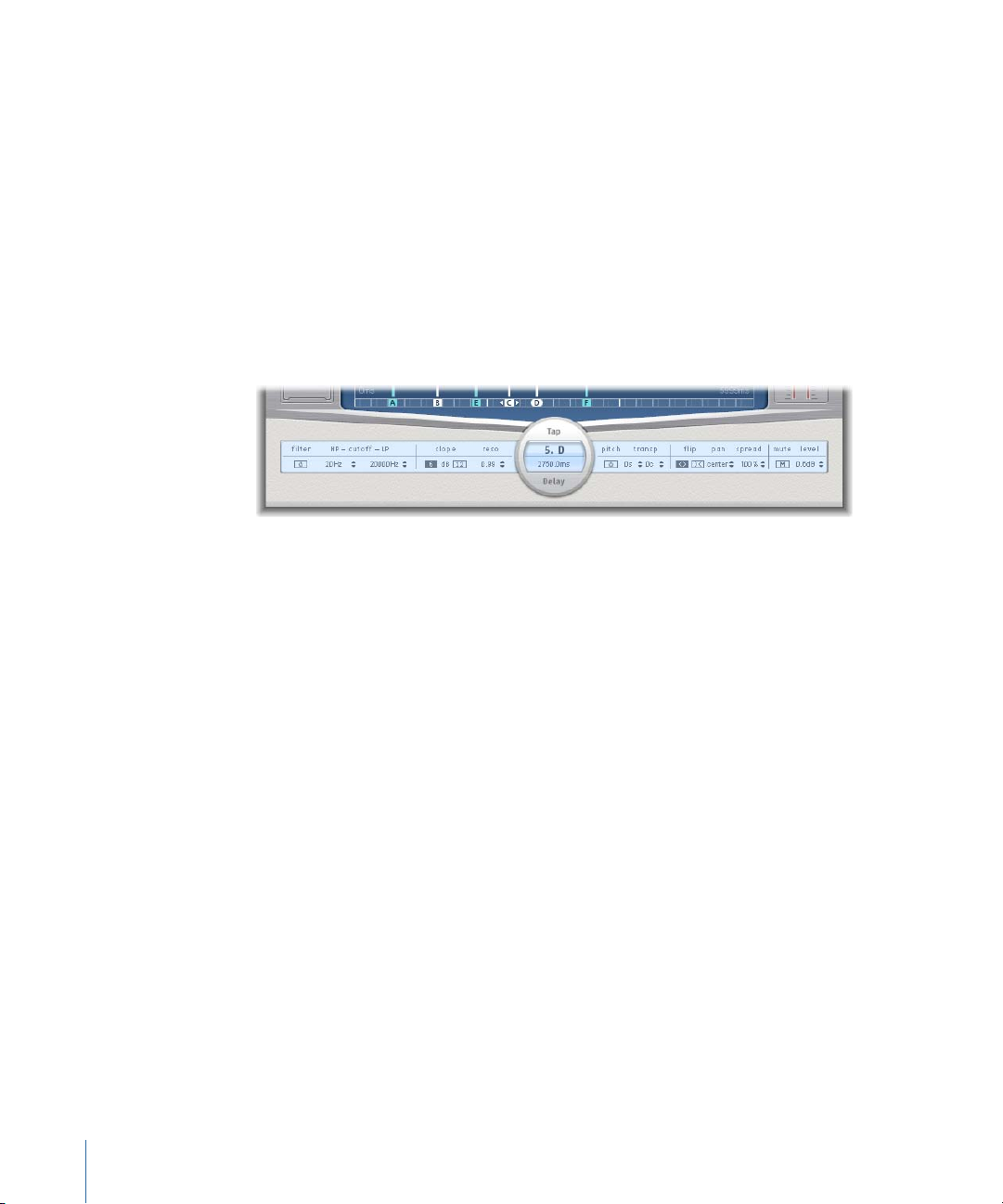
Editing Taps in Delay Designer’s Tap Parameter Bar
The Tap parameter bar provides instant access to all parameters of the chosen tap. The
Tap parameter bar also provides access to several parameters that are not available in
the Tap display, such as Transpose and Flip.
Editing inthe Tap parameter bar is fast and precise when you want to edit the parameters
of a single tap. All parameters of the selected tap are available, with no need to switch
display views or estimate values with vertical lines. If you choose multiple taps in the Tap
display, the values of all selected taps are changed relative to each other.
Option-click a parameter value to reset it tothe default setting. If multiple taps are selected,
Option-clicking a parameter of any tap resets all selected taps to the default value for
that parameter.
• Filter On/Off button: Enables or disables the highpass and lowpass filters for the selected
tap.
• HP-Cutoff-LP fields: Sets the cutoff frequencies (in Hz) for the highpass and lowpass
filters.
• Slope buttons: Determines the steepness of the highpass and lowpass filter slope. Click
the 6 dB button for a gentler filter slope, or click the 12 dB button for a steeper, more
pronounced filtering effect.
Note: You cannot set the slope of the highpass and lowpass filters independently.
• Reso(nance) field: Sets the amount of filter resonance for both filters.
• Tap Delay fields: Shows the number and name of the selected tap in the upper section
and the delay time in the lower section.
• Pitch On/Off button: Enables or disables pitch transposition for the selected tap.
• Transp(ose) fields: The left field sets the amount of pitch transposition in semitones.
The right field fine-tunes each semitone step in cents (1/100th of a semitone).
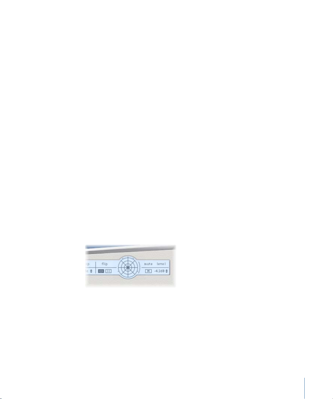
• Flip buttons: Swaps the left and right side of the stereo or surround image. Clicking
these buttons reverses the tap position from left to right, or vice versa. For example, if
a tap is set to 55% left, clicking the flip button will swap it to 55% right.
38 Chapter 2 Echo Effects
Page 39

• Pan field: Controls the pan position for mono input signals, stereo balance for stereo
input signals, and surround angle when used in surround configurations.
• Pan displays a percentage between 100% (full left) and −100% (full right), which
represents the pan positionor balance of the tap. A value of 0% represents the center
panorama position.
• When used in surround, a surround panner replaces the percentage representation.
For more information, see Working with Delay Designer in Surround.
• Spread field: When a stereo-to-stereo or stereo-to-surround instance of Delay Designer
is used, Spread sets the width of the stereo spread for the selected tap.
• Mute button: Mutes or unmutes the selected tap.
• Level field: Determines the output level for the selected tap.
Editing Delay Designer Taps with the Shortcut Menu
Control-click (or right-click) a tap in Delay Designer’s Tap display to open a shortcut menu
containing the following commands:
• Copy sound parameters: Copies all parameters (except the delay time) of the selected
tap or taps into the Clipboard.
• Paste sound parameters: Pastes the tap parameters from the Clipboard into the selected
tap or taps. If there are more taps in the Clipboard than are selected in the Tap display,
the extra taps in the Clipboard are ignored.
• Reset soundparameters todefault values: Resets all parameters of all selected taps (except
the delay time) to the default values.
• 2 x delay time: Doubles the delay time of all selected taps. For example, the delay times
of three taps are set as follows: Tap A = 250 ms, Tap B = 500 ms, Tap C = 750 ms. If you
select these three taps and choose the “2 x delay time” shortcut menu command, the
taps will be changed as follows: Tap A = 500 ms, Tap B = 1000 ms, Tap C = 1500 ms.
In other words, a rhythmic delay pattern will unfold half as fast. (In musical terms, it
will be played in half time.)
• 1/2 x delay time: Halves the delay time of all selected taps. Using the example above,
use of the “1/2 x delay time” shortcut menu command changes the taps as follows: Tap A
= 125 ms, Tap B = 250 ms, Tap C = 375 ms. In other words, a rhythmic delay pattern
will unfold twice as fast. (In musical terms, it will be played in double time.)
• Delete tap(s): Deletes all selected taps.
Resetting Delay Designer Tap Values
You can use Delay Designer’s Tap display and Tap parameter bar to reset tap parameters
to their default values.
39Chapter 2 Echo Effects
Page 40
To reset the value of a tap
Do one of the following:
In the Tap display, Option-click a tap to reset the chosen parameter to its default setting.
µ
If multiple taps are selected, Option-clicking any tap will reset the chosen parameter to
its default value for all selected taps.
In the Tap parameter bar, Option-click a parameter value to reset it to the default setting.
µ
If multiple taps are selected, Option-clicking a parameter of any tap resets all selected
taps to the default value for that parameter.
Using Delay Designer’s Master Section
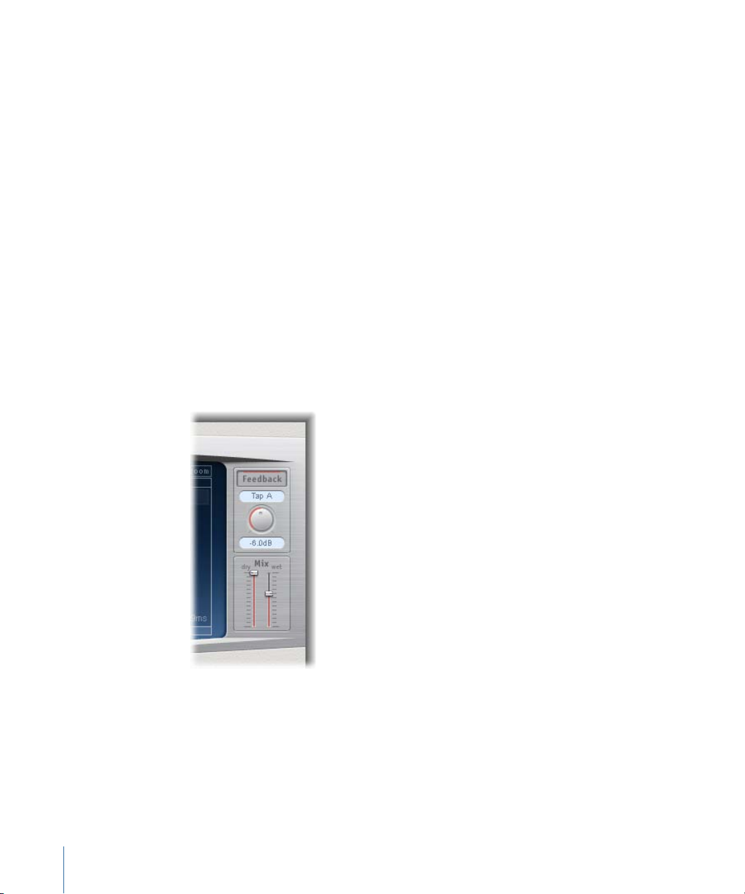
The Master section incorporates two global functions: delay feedback and dry/wet mix.
In simple delays, the only way for the delay to repeat is to use feedback. Because
Delay Designer offers 26 taps, you can use these taps to create repeats, rather than
requiring discrete feedback controls for each tap.
Delay Designer’s global Feedback parameter does, however, allow you to send the output
of one user-defined tap back through the effect input, to create a self-sustaining rhythm
or pattern. This tap is known as the feedback tap.
• Feedback button: Enables or disables the feedback tap.
• Feedback Tap pop-up menu: Used to choose a tap as the feedback tap.
• Feedback Level knob: Sets the feedback level. You can vary the feedback tap output
level before it is routed back into Delay Designer’s input.
• A value of 0% equals no feedback.
40 Chapter 2 Echo Effects
Page 41
• A value of 100% sends the feedback tap back into Delay Designer’s input at full
volume.
Note: If Feedback is enabled and you begin creating taps with the Tap pads, Feedback
is automatically turned off. When you stop creating taps with the Tap pads, Feedback
is automatically re-enabled.
• Mix sliders: Independentlyset the levels of the dry input signal andthe post-processing
wet signal.
Working with Delay Designer in Surround
Delay Designer’s design is optimized for use in surround configurations. With 26 taps that
can be freely positioned in the surround field, you can create some truly amazing rhythmic
and spatial effects.
Delay Designer always processes each input channel independently.
• In a mono/stereo input and surround output configuration, Delay Designer processes
the two stereo channels independently, and the surround panner lets you place each
delay around the surround field.
• In a surround input and surround output configuration, Delay Designer processes each
surround channel independently, and the surround panner lets you adjust the surround
balance of each tap in the surround field.
When you instantiate Delay Designer in any surround configuration, the Pan parameter
on the Tap parameter bar is replaced with a surround panner, allowing you to determine
the surround position of each tap.
Note: In the Tap display’s Pan view mode, you can only adjust the angle of taps. You must
use the surround panner on the Tap Parameter bar to adjust diversity.
To easily move the surround position, you can:
• Command-drag to adjust diversity.
• Command-Option-drag to adjust the angle.
• Option-click the blue dot to reset the angle and diversity.
Note: Delay Designer generates separate automation data for stereo pan and surround
pan operations. This means that when you use it in surround channels, it will not react
to existing stereo pan automation data, and vice versa.
41Chapter 2 Echo Effects
Page 42

Modulation Delay
The Modulation Delay is based on the same principles as the Flanger and Chorus effects,
but you can set the delay time, allowing both chorus and flanging effects to be generated.
It can also be used without modulation to create resonator or doubling effects. The
modulation section consists of two LFOs with variable frequencies.
Although rich, combined flanging and chorus effects are possible, the Modulation Delay
is capable of producing some extreme modulation effects. These include emulations of
tape speed fluctuations and metallic, robot-like modulations of incoming signals.
• Feedbackslider andfield: Determines the amount of theeffect signal that is routed back
to the input. If you’re going for radical flanging effects, enter a high Feedback value. If
simple doubling is what you’re after, don’t use any feedback. Negative values invert
the phase of the feedback signal, resulting in more chaotic effects.
• Flanger-Chorus knob and field: Sets the basic delay time. Set to the far left position to
create flanger effects, to the center for chorus effects, and to the far right to hear clearly
discernible delays.
• De-Warble button: Ensures that the pitch of the modulated signal remains constant.
• Const Mod. (Constant Modulation) button: Ensures that the modulation width remains
constant, regardless of the modulation rate.
Note: When Const Mod is enabled, higher modulation frequencies reduce the
modulation width.
• Mod. Intensity slider and field: Sets the modulation amount.
• LFO Mix slider and fields: Determines the balance between the two LFOs.
• LFO 1 and LFO 2 Rate knobs and fields: The left knob sets the modulation rate for the
left stereo channel, and the right knob sets the modulation rate for the right stereo
channel.
In surround instances, the center channel is assigned the middle value of the left and
right LFO Rate knobs. The other channels are assigned values between the left and
right LFO rates.
42 Chapter 2 Echo Effects
Page 43

Note: The right LFO Rate knob is available only in stereo and surround instances, and
it can be set separately only if the Left Right Link button is not enabled.
• LFO Left Right Link button: Available only in stereo and surround instances, it links the
modulation rates of the left and right stereo channels. Adjustment of either Rate knob
will affect the other channels.
• LFO Phase knob and field: Available only in stereo and surround instances, it controls
the phase relationship between individual channel modulations.
• At 0°, the extreme values of the modulation are achieved simultaneously for all
channels.
• 180° or −180° is equal to the greatest possible distance between the modulation
phases of the channels.
Note: The LFO Phase parameter is available only if the LFO Left Right Link button is
active.
• Distribution pop-upmenu: Available only in surround instances, it defines how the phase
offsets between the individual channels are distributed in the surround field. You can
choose from “circular,” “left↔right,” “front↔rear,” “random,” and “new random”
distributions.
Note: When you load a setting that uses the “random” option, the saved phase offset
value isrecalled. If you want to randomize the phase setting again, choose “new random”
from the Distribution pop-up menu.
• Volume Mod(ulation) slider and field: Determines the impact that LFO modulation has
on the amplitude of the effect signal.
• Output Mix slider and field: Determines the balance between dry and wet signals.
• All Pass button (Extended Parameters area): Introduces an additional allpass filter into
the signal path. An allpass filter shifts the phase angle of a signal, influencing its stereo
image.
• All Pass Left and All Pass Right sliders and fields (Extended Parameters area): Determines
the frequency at which the phase shift crosses 90° (the half-way point of the total 180°)
for each of the stereo channels. In surround instances, the other channels are
automatically assigned values that fall between the two settings.
43Chapter 2 Echo Effects
Page 44

Stereo Delay
The Stereo Delay works much like the Tape Delay (see Tape Delay), but allows you to set
the Delay, Feedback, and Mix parameters separately for the left and right channels. The
Crossfeed knob for each stereo side determines the feedback intensity or the level at
which each signal is routed to the opposite stereo side. You can freely use the Stereo
Delay on mono channels when you want to create independent delays for the two stereo
sides.
As the parameters for the left and right delays are identical, the descriptions below only
cover the left channel—the right channel information is provided in brackets, if named
differently. Parameters that are common to both channels are shown separately.
Channel Parameters
• Left (Right)Input pop-up menu: Choose the input signal for the two stereo sides. Options
include OFF, Left, Right, L + R, L − R.
• Left (Right) Delay field: Sets the current delay time in milliseconds (this parameter is
dimmed when you synchronize the delay time to the project tempo).
• Groove slider and field: Determines the proximity of every second delay repeat to the
absolute grid position—in other words, how close every second delay repeat is.
• Note buttons: Set the grid resolution for the delay time. These are shown as note
durations (these are dimmed when the delay time is not synchronized with the project
tempo).
• Left (Right) Feedback knob and field: Set the amount of feedback for the left and right
delay signals.
44 Chapter 2 Echo Effects
Page 45

• Crossfeed Left to Right(Crossfeed Right to Left) knoband field: Transfer the feedback signal
of the left channel to the right channel, and vice versa.
• FeedbackPhase button: Use to invert the phase of the corresponding channel’s feedback
signal.
• Crossfeed Phase button: Use to invert the phase of the crossfed feedback signals.
Common Parameters
• Beat Sync button: Synchronizes delay repeats to the project tempo, including tempo
changes.
• Output Mix (Left and Right) sliders and fields: Independently control the left and right
channel signals.
• Low Cut and High Cut sliders and fields: Frequencies below the Low Cut value and above
the High Cut value are filtered out of the source signal.
Tape Delay
Tape Delay simulates the warm sound of vintage tape echo machines, with the
convenience of easy delay time synchronization to your project tempo. The effect is
equipped with a highpass and lowpass filter in the feedback loop, simplifying the creation
of authentic dub echo effects. Tape Delay alsoincludes an LFO for delay time modulation,
which can be used to produce pleasant or unusual chorus effects, even on long delays.
• Feedback slider: Determines the amount of delayed and filtered signal that is routed
back to the input of the Tape Delay. Set the Feedback slider to the lowest possible
value to generate a single echo. Turn Feedback all the way up to endlessly repeat the
signal. The levels of the original signal and its taps (echo repeats) tend to accumulate,
and may cause distortion. You can use the internal tape saturation circuit to ensure
that these overdriven signals continue to sound good.
• Freeze button: Captures the current delay repeats and sustains them until the Freeze
button is turned off.
45Chapter 2 Echo Effects
Page 46

• Delay field: Sets the current delay time in milliseconds (this parameter is dimmed when
you synchronize the delay time to the project tempo).
• Sync button: Synchronizes delay repeats to the project tempo (including tempochanges).
• Tempofield: Sets the current delay time in beats per minute (this parameter is dimmed
when you synchronize the delay time to the project tempo).
• Groove slider and field: Determines the proximity of every second delay repeat to the
absolute grid position—in other words, how close every second delay repeat is. A
Groove setting of 50% means that every delay has the same delay time. Settings below
50% result in every second delay being played earlier in time. Settings above 50% result
in every second delay being played later in time. When you want to create dotted note
values, move the Groove slider all the way to the right (to 75%). For triplets, select the
33.33% setting.
• Note buttons: Set the grid resolution for the delay time. These are shown as note
durations.
• Low Cut and High Cut sliders and fields: Frequencies below the Low Cut value and above
the High Cut value are filtered out of the source signal. You can shape the sound of
the echoes with the highpass and lowpass filters. The filters are located in the feedback
circuit, which means that the filtering effect increases in intensity with each delay
repeat. If you want an increasingly muddy and confused tone, move the High Cut slider
towards the left. For ever thinner echoes, move the Low Cut slider towards the right.
If you’re unable to hear the effect even though you seem to have a suitable
configuration, be sure to check out both the Dry and Wet controls and the filter
settings—move the High Cut slider to the far right, and the Low Cut slider to the far
left.
• Smooth slider and field: Evens out the LFO and flutter effect.
• LFO Rate knob and field: Sets the frequency of the LFO.
• LFO Depth knob andfield: Sets the amount of LFO modulation. A value of 0 turns delay
modulation off.
• Flutter Rate and Intensity sliders and fields: Simulate the speed irregularities of the tape
transports used in analog tape delay units.
• Flutter Rate: Sets the speed variation.
• Flutter Intensity: Determines how pronounced the effect is.
• Dry and Wet sliders and fields: Independently control the amount of original and effect
signal.
• Distortion Level slider and field (Extended Parameters area): Determines the level of the
distorted (tape saturation) signal.
46 Chapter 2 Echo Effects
Page 47

Equalizers
3
An equalizer (commonly abbreviated as EQ) shapes the sound of incoming audio by
changing the level of specific frequency bands.
Equalization is one of the most commonly used audio processes, both for music projects
and in post-production work for video. You can use EQ to subtly or significantly shape
the sound of an audio file, instrument, or project by adjusting specific frequencies or
frequency ranges.
All EQs are specialized filters that allow certain frequencies to pass through unchanged
while raising (boosting) or lowering (cutting) the level of other frequencies. Some EQs
can beused in a “broad-brush” fashion, to boost or cut alarge range of frequencies. Other
EQs, particularly parametric and multiband EQs, can be used for more precise control.
The simplest types of EQs are single-band EQs, which include low cut and high cut,
lowpass and highpass, shelving, and parametric EQs.
Multiband EQs (such as the Channel EQ, Fat EQ, or Linear Phase EQ) combine several
filters in one unit, enabling you to control a large part of the frequency spectrum.
Multiband EQs allow you to independently set the frequency, bandwidth, and Q factor
of each frequency spectrum band. This provides extensive, and precise, tone-shaping on
any audio source, be it an individual audio signal or an overall mix.
Final Cut Pro includes a variety of single band and multiband EQs.
This chapter covers the following:
• AutoFilter (p. 47)
• Channel EQ (p. 53)
• Fat EQ (p. 56)
• Linear Phase EQ (p. 57)
AutoFilter
The AutoFilter is a versatile filter effect with several unique features. You can use it to
create classic, analog-style synthesizer effects, or as a tool for creative sound design.
47
Page 48

The effect works by analyzing incoming signallevels through use of a threshold parameter.
Filter parametersThreshold parameter Envelope parameters
Distortion parametersLFO parameters
Output parameters
Any signal level that exceeds the threshold is used as a trigger for a synthesizer-style
ADSR envelope or an LFO (low frequency oscillator). These control sources are used to
dynamically modulate the filter cutoff.
The AutoFilter allows you to choose between different filter types and slopes, control the
amount of resonance, add distortion for more aggressive sounds, and mix the original,
dry signal with the processed signal.
Getting to Know the AutoFilter Interface
The main areas of the AutoFilter window are the Threshold, Envelope, LFO, Filter, Distortion,
and Output parameter sections.
• Threshold parameter: Sets an input level that—if exceeded—triggers the envelope or
LFO, which are used to dynamically modulate the filter cutoff frequency. See AutoFilter
Threshold Parameter.
• Envelope parameters: Define how the filter cutoff frequency is modulated over time.
See AutoFilter Envelope Parameters.
• LFO parameters: Define how the filter cutoff frequency is modulated by the LFO. See
AutoFilter LFO Parameters.
• Filter parameters: Control the tonal color of the filtered sound. See AutoFilter Filter
Parameters.
• Distortion parameters: Distort the signal both before and after the filter. See AutoFilter
Distortion Parameters.
• Output parameters: Set the level of both the dry and effect signal. See AutoFilter Output
Parameters.
48 Chapter 3 Equalizers
Page 49
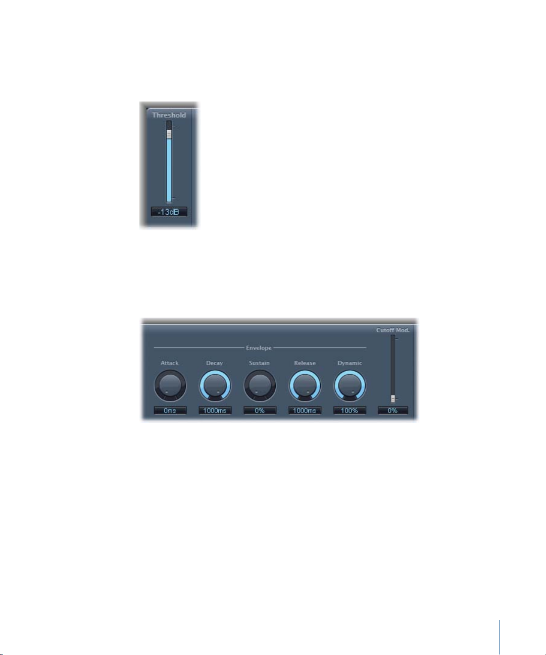
AutoFilter Threshold Parameter
The Threshold parameter analyzes the level of the input signal. If the input signal level
exceeds the set threshold level, the envelope and LFO are retriggered—this applies only
if the Retrigger button is active.
The envelope and LFO can be used to modulate the filter cutoff frequency.
AutoFilter Envelope Parameters
The envelope is used to shape the filter cutoff over time. When the input signal exceeds
the set threshold level, the envelope is triggered.
• Attack knob and field: Sets the attack time for the envelope.
• Decay knob and field: Sets the decay time for the envelope.
• Sustain knob and field: Sets the sustain time for the envelope. If the input signal falls
below the threshold level before the envelope sustain phase, the release phase is
triggered.
• Release knob and field: Sets the release time for the envelope (this is triggered as soon
as the input signal falls below the threshold).
• Dynamic knob and field: Determines the input signal modulation amount. You can
modulate the peak value of the envelope section by varying this control.
• Cutoff Mod. slider and field: Determines the impact of the envelope on the cutoff
frequency.
49Chapter 3 Equalizers
Page 50
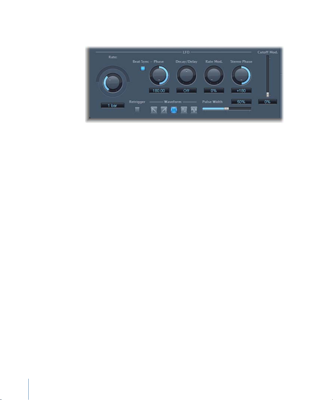
AutoFilter LFO Parameters
The LFO is used as a modulation source for filter cutoff.
• Coarse Rate knob, Fine Rate slider and field: Used to set the speed of LFO modulation.
Drag the Coarse Rate knob to set the LFO frequency in Hertz. Drag the Fine Rate slider
(the semicircular slider above the Coarse Rate knob) to fine-tune the frequency.
Note: The labels shown for the Rate knob, slider, and field change when you activate
Beat Sync. Only the Rate knob (and field) is available.
• Beat Sync button: Activate to synchronize the LFO to the host application tempo. You
can choose from bar values, triplet values, and more. These are determined by the Rate
knob or field.
• Phase knob and field: Shifts the phase relationship between the LFO rate and the host
application tempo—when Beat Sync is active. This parameter is dimmed when Beat
Sync is disabled.
• Decay/Delay knob and field: Sets the amount of time it takes for the LFO to go from 0
to its maximum value.
• Rate Mod. knob andfield: Sets the rate of modulation for the LFO frequency, independent
of the input signal level. Typically, when the input signal exceeds the threshold, the
modulation width of the LFO increases from 0 to the Rate Mod. value. This parameter
allows you to override this behavior.
• Stereo Phase knob and field: In stereo instances of the AutoFilter, sets the phase
relationship of the LFO modulations between the two channels.
• Cutoff Mod. slider and field: Determines the impact of the LFO on the cutoff frequency.
• Retrigger button: When the Retrigger button is active, the waveform starts at 0 each
time the threshold is exceeded.
• Waveform buttons: Click one of the following buttons to set the shape of the LFO
waveform: descending sawtooth, ascending sawtooth, triangle, pulse wave, or random.
• Pulse Width slider and field: Shapes the curve of the selected waveform.
50 Chapter 3 Equalizers
Page 51

AutoFilter Filter Parameters
The Filter parameters allow you to precisely tailor the tonal color.
• Cutoff knob and field: Sets the cutoff frequency for the filter. Higher frequencies are
attenuated, whereas lower frequencies are allowed to pass through in a lowpass filter.
The reverse is true in a highpass filter. When the State Variable Filter is set to bandpass
(BP) mode, the filter cutoff determines the center frequency ofthe frequency band that
is allowed to pass.
• Resonance knoband field: Boosts or cuts the signals in the frequency bandthat surrounds
the cutoff frequency. Use of very high Resonance values causes the filter to begin
oscillating at the cutoff frequency. This self-oscillation occurs before you reach the
maximum Resonance value.
• Fatnessslider andfield: Boosts the level of lowfrequency content. When you set Fatness
to its maximum value, adjusting Resonance has no effect on frequencies below the
cutoff frequency. This parameter is used to compensate for a weak or “brittle” sound
caused by high resonance values, when in the lowpass filter mode.
• State Variable Filter buttons: Switch the filter between highpass (HP), bandpass (BP), or
lowpass (LP) modes.
• 4-Pole Lowpass Filter buttons: Set the slope of the filter to 6, 12, 18, or 24 dB per
octave—when the lowpass (LP) filter is chosen as the State Variable Filter.
51Chapter 3 Equalizers
Page 52
AutoFilter Distortion Parameters
The Distortion parameters can be used to overdrive the filter input or filter output. The
distortion input and output modules are identical, but their respective positions in the
signal chain—before and after the filter, respectively—result in remarkably different
sounds.
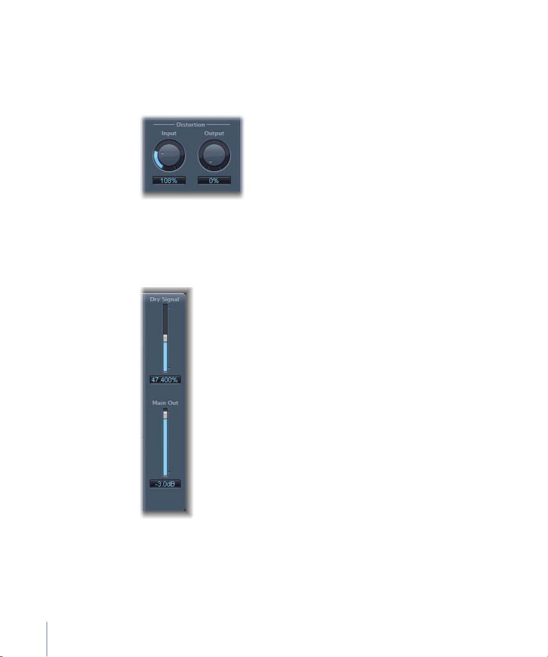
• Input knob and field: Sets the amount of distortion applied before the filter section.
• Output knob and field: Sets the amount of distortion applied after the filter section.
AutoFilter Output Parameters
The Output parameters are used to set the wet/dry balance and overall level.
• Dry Signal sliderand field: Sets the amount of the original dry signal added to the filtered
signal.
• Main Out slider and field: Sets the overall output level of the AutoFilter, allowing you
to compensate for higher levels caused by adding distortion—or by thefiltering process
itself.
52 Chapter 3 Equalizers
Page 53
Channel EQ
The Channel EQ is a highly versatile multiband EQ. It provides eight frequency bands,
including lowpass and highpass filters, low and high shelving filters, and four flexible
parametric bands. It also features an integrated Fast Fourier Transform (FFT) Analyzer that
you can use to view the frequency curve of the audio you want to modify, allowing you
to see which parts of the frequency spectrum may need adjustment.
You can use the Channel EQ to shape the sound of an individual clip. The Analyzer and
graphic controls make it easy to view and change the audio signal in real time.
Channel EQ Parameters
The left side of the Channel EQ window features the Gain and Analyzer controls. The
central area of the window includes the graphic display and parameters for shaping each
EQ band.
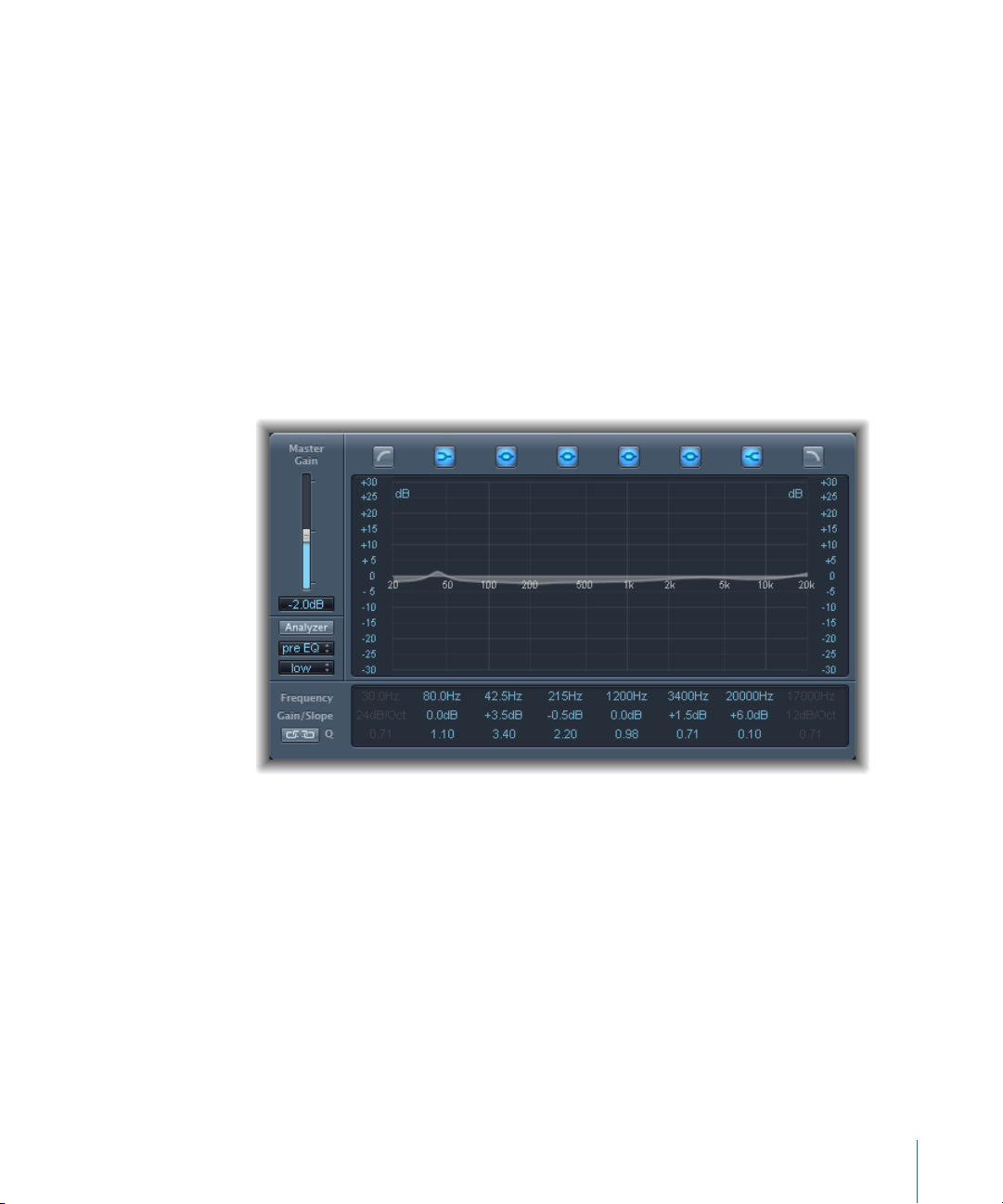
Channel EQ Gain and Analyzer Controls
• Master Gain slider and field: Sets the overall output level of the signal. Use it after
boosting or cutting individual frequency bands.
• Analyzer button: Turns the Analyzer on or off.
• Pre/PostEQ button: Determines whether the Analyzer shows the frequency curve before
or after EQ is applied, when Analyzer mode is active.
• Resolution pop-upmenu: Sets the sample resolution for the Analyzer, with the following
menu items: low (1024 points), medium (2048 points), and high (4096 points).
Channel EQ Graphic Display Section
• Band On/Off buttons: Click to turn the corresponding band on or off. Each button icon
indicates the filter type:
53Chapter 3 Equalizers
Page 54

Band 1 is a highpass filter.
Band 2 is a low shelving filter.
Bands 3 through 6 are parametric bell filters.
Band 7 is a high shelving filter.
Band 8 is a lowpass filter.
• Graphic display: Shows the current curve of each EQ band.
• Drag horizontally in the section of the display that encompasses each band to adjust
the frequency of the band.
• Drag vertically in the section of the display that encompasses each band to adjust
the gain of each band (except bands 1 and 8). The display reflects your changes
immediately.
• Drag the pivot point in each band to adjust the Q factor. Q is shown beside the cursor
when it is moved over a pivot point.
Channel EQ Parameter Section
• Frequency fields: Adjust the frequency of each band.
• Gain/Slope fields: Set the amount of gainfor each band. For bands 1 and 8,this changes
the slope of the filter.
• Q fields: Adjust the Q factor or resonance for each band—the range of frequencies
around the center frequency that are affected.
Note: The Q parameter of Band 1 and Band 8 has no effect when the slope is set to
6 dB/Oct. When the Q parameter is set to an extremely high value, such as 100, these
filters affect only a very narrow frequency band and can be used as notch filters.
• Link button: Activates Gain-Q coupling, which automatically adjusts the Q (bandwidth)
when you raise or lower the gain on any EQ band, to preserve the perceived bandwidth
of the bell curve.
• Analyzer Mode buttons (Extended Parameters area): Choose Peak or RMS.
• Analyzer Decay slider and field (Extended Parameters area): Adjust the decay rate (in dB
per second) of the Analyzer curve (peak decay in Peak mode or an averaged decay in
RMS mode).
• Gain-Q Couple Strength pop-up menu (Extended Parameters area): Choose the amount
of Gain-Q coupling.
• Choose “strong” to preserve most of the perceived bandwidth.
• Choose “light” or “medium” to allow some change as you raise or lower the gain.
• The asymmetric settings feature a stronger coupling for negative gain values than
for positive values, so the perceived bandwidth is more closely preserved when you
cut, rather than boost, gain.
54 Chapter 3 Equalizers
Page 55

Note: If you play back automation of the Q parameter with a different Gain-Q Couple
setting, the actual Q values will be different than when the automation was recorded.
Using the Channel EQ
The way you use the Channel EQ is obviously dependent on the audio material and what
you intend to do with it, but a useful workflow for many situations is as follows: Set the
Channel EQ to a flat response (no frequencies boosted or cut), turn on the Analyzer and
play the audio signal. Keep an eye on the graphic display to see which parts of the
frequency spectrum have frequent peaks and which parts of the spectrum stay at a low
level. Pay particular attention to sections where the signal distorts or clips. Use the graphic
display or parameter controls to adjust the frequency bands as desired.
You can reduce or eliminate unwanted frequencies, and you can raise quieter frequencies
to make them more pronounced. You can adjust the center frequencies of bands 2
through 7 to affect a specific frequency—either one you want to emphasize, such as the
root note of the music, or one you want to eliminate, such as hum or other noise. While
doing so, change the Q parameter(s) so that only a narrow range of frequencies are
affected, or widen it to alter a broad area.
Each EQ band has a different color in the graphic display. You can graphically adjust the
frequency of a band by dragging horizontally. Drag vertically to adjust the amount of
gain for the band. For bands 1 and 8, the slope values can be changed only in the
parameter area below the graphic display. Each band has a pivot point (a small circle on
the curve) at the location of the band’s frequency; you can adjust the Q or width of the
band by dragging the pivot point vertically.
You can also adjust the decibel scale of the graphic display by vertically dragging either
the left or right edge of the display, where the dB scale is shown, when the Analyzer is
not active. When the Analyzer is active, dragging the left edge adjusts the linear dB scale,
and dragging the right edge adjusts the Analyzer dB scale.
To increase the resolution of the EQ curve display in the most interesting area around
the zero line, drag the dB scale, on the left side of the graphic display, upward. Drag
downward to decrease the resolution.
Using the Channel EQ Analyzer
The Analyzer, when active, makes uses of a mathematical process called a Fast Fourier
Transform (FFT) to provide a real-time curve of all frequency components in the incoming
signal. This is superimposed over any EQ curves you have set. The Analyzer curve uses
the same scale as the EQ curves, making it easy to recognize important frequencies in
the incoming audio. This also simplifies the task of setting EQ curves to raise or lower the
levels of frequencies/frequency ranges.
The bands derived from FFT analysis are divided in a logarithmic scale—there are more
bands in higher octaves than in lower ones.
55Chapter 3 Equalizers
Page 56
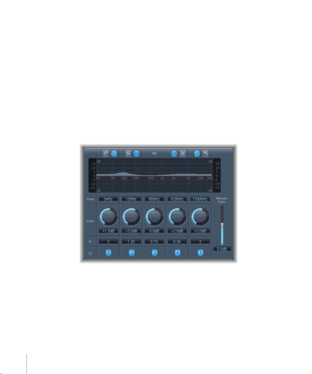
As soon as the Analyzer is activated, you can change the scaling with the Analyzer Top
parameter, on the right side of the graphic display. The visible area represents a dynamic
range of 60 dB. Drag vertically to set the maximum value to anywhere between +20 dB
and −80 dB. The Analyzer display is always dB-linear.
Note: When choosing a resolution, be aware that higher resolutions require significantly
more processing power. High resolution is necessary when trying to obtain accurate
analysis of very low bass frequencies, for example. It is recommended that you disable
the Analyzer or close the Channel EQ window after setting the appropriate EQ parameters.
This will free up CPU resources for other tasks.
Fat EQ
The Fat EQ is a versatile multiband EQ which can be used on individual sources or overall
mixes. The Fat EQ provides up to five individual frequency bands, graphically displays
EQ curves, and includes a set of parameters for each band.
The Fat EQ offers the following parameters.
• Band Type buttons: Located above the graphic display. For bands 1–2 and 4–5, click
one of the paired buttons to select the EQ type for the corresponding band.
• Band 1: Click the highpass or low shelving button.
• Band 2: Click the low shelving or parametric button.
• Band 3: Always acts as a parametric EQ band.
• Band 4: Click the parametric or high shelving button.
56 Chapter 3 Equalizers
Page 57

• Band 5: Click the high shelving or lowpass button.
• Graphic display: Shows the EQ curve of each frequency band.
• Frequency fields: Sets the frequency for each band.
• Gain knobs: Set the amount of gain for each band.
• Q fields: Sets the Q or bandwidth of each band—the range of frequencies around the
center frequency that are altered. At low Q factor values, the EQ covers a wider frequency
range. At high Q values, the effect of the EQ band is limited to a narrow frequency
range. The Q value can significantly influence how audible your changes are—if you’re
working with a narrow frequency band, you’ll generally need to cut or boost more
drastically to notice the difference.
Note: For bands 1 and 5, this changes the slope of the filter.
• Band On/Off buttons: Enables/disables the corresponding band.
• Master Gain slider and field: Sets the overall output level of the signal. Use it after
boosting or cutting individual frequency bands.
Linear Phase EQ
The high-quality Linear Phase EQ effect is similar to the Channel EQ, sharing the same
parameters and eight-band layout. The Linear Phase EQ uses a different underlying
technology, however, which perfectly preserves the phase of the audio signal. This phase
coherency is assured, even when you apply the wildest EQ curves to the sharpest signal
transients.
A further difference is that the Linear Phase EQ uses a fixed amount of CPU resources,
regardless of how many bands are active. The Linear Phase EQ also introduces greater
amounts of latency. Therefore, it is strongly recommended that you use it for mastering
previously recorded audio.
57Chapter 3 Equalizers
Page 58

Linear Phase EQ Parameters
The left side of the Channel EQ window includes the Gain and Analyzer controls. The
central area of the window includes the graphical display and parameters for shaping
each EQ band.
Linear Phase EQ Gain and Analyzer Controls
• Master Gain slider and field: Sets the overall output level of the signal. Use it after
boosting or cutting individual frequency bands.
• Analyzer button: Turns the Analyzer on or off.
• Pre/PostEQ button: Determines whether the Analyzer shows the frequency curve before
or after EQ is applied, when Analyzer mode is active.
• Resolution pop-upmenu: Sets the sample resolution for the Analyzer, with the following
menu items: low (1024 points), medium (2048 points), and high (4096 points).
Linear Phase EQ Graphic Display Section
• Band On/Off buttons: Click to turn the corresponding band on or off. Each button icon
indicates the filter type:
Band 1 is a highpass filter.
Band 2 is a low shelving filter.
Bands 3 through 6 are parametric bell filters.
Band 7 is a high shelving filter.
Band 8 is a lowpass filter.
58 Chapter 3 Equalizers
Page 59

• Graphic display: Shows the current curve of each EQ band.
• Drag horizontally in the section of the display that encompasses each band to adjust
the frequency of the band.
• Drag vertically in the section of the display that encompasses each band to adjust
the gain of each band (except bands 1 and 8). The display reflects your changes
immediately.
• Drag the pivot point in each band to adjust the Q factor. Q is shown beside the cursor
when the mouse is moved over a pivot point.
Linear Phase EQ Parameter Section
• Frequency fields: Adjust the frequency of each band.
• Gain/Slope fields: Set the amount of gainfor each band. For bands 1 and 8,this changes
the slope of the filter.
• Q fields: Adjust the Q or resonance for each band—the range of frequencies around
the center frequency that are affected.
Note: The Q parameter of Band 1 and Band 8 has no effect when the slope is set to
6 dB/Oct. When the Q parameter is set to an extremely high value (such as 100), these
filters affect only a very narrow frequency band, and can be used as notch filters.
• Link button: Activates Gain-Q coupling, which automatically adjusts the Q (bandwidth)
when you raise or lower the gain on any EQ band, to preserve the perceived bandwidth
of the bell curve.
• Analyzer Mode buttons (Extended Parameters area): Choose Peak or RMS.
• Analyzer Decay slider and field (Extended Parameters area): Adjust the decay rate (in dB
per second) of the Analyzer curve (peak decay in Peak mode or an averaged decay in
RMS mode).
• Gain-Q Couple Strength pop-up menu (Extended Parameters area): Choose the amount
of Gain-Q coupling.
• Set Gain-Q Couple to strong to preserve most of the perceived bandwidth.
• Light and medium settings allow some change as you raise or lower the gain.
• The asymmetric settings feature a stronger coupling for negative gain values than
for positive values, so the perceived bandwidth is more closely preserved when you
cut, rather than boost, gain.
Note: If you play back automation of the Q parameter with a different Gain-Q Couple
setting, the actual Q values will be different than they were when the automation was
recorded.
59Chapter 3 Equalizers
Page 60

Using the Linear Phase EQ
The Linear Phase EQ is typically used as a mastering tool and is, therefore, generally
inserted into master or output audio. The way you use the Linear Phase EQ is obviously
dependent on the audio material and what you intend to do with it, but a useful workflow
for many situations is as follows: Set the Linear Phase EQ to a flat response (no frequencies
boosted or cut), turn on the Analyzer, and play the audio signal. Keep an eye on the
graphic display to see which parts of the frequency spectrum have frequent peaks and
which parts of the spectrum stay at a low level. Pay particular attention to sections where
the signal distorts or clips. Use the graphic display or parameter controls to adjust the
frequency bands as desired.
You can reduce or eliminate unwanted frequencies, and you can raise quieter frequencies
to make them more pronounced. You can adjust the center frequencies of bands 2
through 7 to affect a specific frequency—either one you want to emphasize, such as the
root note of the music, or one you want to eliminate, such as hum or other noise. While
doing so, change the Q parameter(s) so that only a narrow range of frequencies are
affected, or widen it to alter a broad area.
Each EQ band has a different color in the graphic display. You can graphically adjust the
frequency of a band by dragging horizontally. Drag vertically to adjust the amount of
gain for the band. For bands 1 and 8, the slope values can be changed only in the
parameter area below the graphic display. Each band has a pivot point (a small circle on
the curve) at the location of the band’s frequency; you can adjust the Q or width of the
band by dragging the pivot point vertically.
You can also adjust the decibel scale of the graphic display by vertically dragging either
the left or right edge of the display, where the dB scale is shown, when the Analyzer is
not active. When the Analyzer is active, dragging the left edge adjusts the linear dB scale,
and dragging the right edge adjusts the Analyzer dB scale.
To increase the resolution of the EQ curve display in the most interesting area around
the zero line, drag the dB scale, on the left side of the graphic display, upward. Drag
downward to decrease the resolution.
Using the Linear Phase EQ Analyzer
The Analyzer, when active, makes use of a mathematical process called a Fast Fourier
Transform (FFT) to provide a real-time curve of all frequency components in the incoming
signal. This is superimposed over any EQ curves you have set. The Analyzer curve uses
the same scale as the EQ curves, making it easy to recognize important frequencies in
the incoming audio. This also simplifies the task of setting EQ curves to raise or lower the
levels of frequencies or frequency ranges.
The bands derived from FFT analysis are divided in accordance with the frequency linear
principle—there are more bands in higher octaves than in lower ones.
60 Chapter 3 Equalizers
Page 61

As soon as the Analyzer is activated, you can change the scaling with the Analyzer Top
parameter, on the right side of the graphic display. The visible area represents a dynamic
range of 60 dB. Drag vertically to set the maximum value to anywhere between +20 dB
and −40 dB. The Analyzer display is always dB-linear.
Note: When choosing a resolution, be aware that higher resolutions require significantly
more processing power. High resolution is necessary when trying to obtain accurate
analysis of very low bass frequencies, for example. It is recommended that you disable
the Analyzer or close the Linear Phase EQ window after setting the appropriate
EQ parameters. This will free up CPU resources for other tasks.
61Chapter 3 Equalizers
Page 62

Page 63

Levels Effects
4
The levels effects control the perceived loudness of your audio, add focus and punch to
clips, and optimize the sound for playback in different situations.
The dynamic range of an audio signal is the range between the softest and loudest parts
of the signal—technically, between the lowest and highest amplitudes. Dynamics
processors enable you to adjust the dynamic range of individual audio clips. This can be
to increase the perceived loudness and/or to highlight the most important sounds, while
ensuring that softer sounds are not lost in the mix.
This chapter covers the following:
• Types of Dynamics Processors (p. 63)
• Adaptive Limiter (p. 65)
• Compressor (p. 66)
• Enveloper (p. 70)
• Expander (p. 72)
• Gain Plug-in (p. 73)
• Limiter (p. 73)
• Multichannel Gain (p. 75)
• Multipressor (p. 75)
• Noise Gate (p. 78)
• Spectral Gate (p. 81)
• Surround Compressor (p. 83)
Types of Dynamics Processors
There are four types of dynamics processors included in Final Cut Pro. These are each
used for different audio processing tasks.
• Compressors: Final Cut Pro features a number of downward compressors. These behave
like an automatic volume control, lowering the volume whenever it rises above a certain
level, called the threshold. So, why would you want to reduce the dynamic level?
63
Page 64

By reducing the highest parts of the signal, called peaks, acompressor raises the overall
level of the signal, increasing the perceived volume. This gives the signal more focus
by making the louder (foreground)parts stand out, while keeping the softer background
parts from becoming inaudible. Compression also tends to make sounds tighter or
punchier because transients are emphasized, depending on attack and release settings,
and because the maximum volume is reached more swiftly.
In addition, compression can make a project sound better when played back in different
audio environments. For example, the speakers of a television set or in a car typically
have a narrower dynamic range than the sound system in a cinema. Compressing the
overall mix can help make the sound fuller and clearer in lower-fidelity playback
situations.
Compressors are typically used on dialogue clips to make the speech more intelligible
in an overall mix. They are also commonly used on music and sound effect clips, but
they are rarely used on ambience clips.
Some compressors—multiband compressors—can divide the incoming signal into
different frequency bands and apply different compression settings to each band. This
helps to achieve the maximum level without introducing compression artifacts.
Multiband compression is typically used on an overall mix.
• Expanders: Expanders are similar to compressors, except that they raise, rather than
lower, the signal when it exceeds the threshold. Expanders are used to add life to audio
signals.
• Limiters: Limiters—also called peak limiters—work in a similar way to compressors in
that they reduce the audio signal when it exceeds a set threshold. The difference is
that whereas a compressor gradually lowers signal levels that exceed the threshold, a
limiter quickly reduces any signal that is louder than the threshold, to the threshold
level. The main use of a limiter is to prevent clipping while preserving the maximum
overall signal level.
• Noise gates: Noise gates alter the signal in a way that is opposite to that used by
compressors or limiters. Whereas a compressor lowers the level when the signal is
louder than the threshold, a noise gate lowers the signal level whenever it falls below
the threshold. Louder sounds pass through unchanged, but softer sounds, such as
ambient noise or the decay of a sustained instrument, are cut off. Noise gates are often
used to eliminate low-level noise or hum from an audio signal.
64 Chapter 4 Levels Effects
Page 65
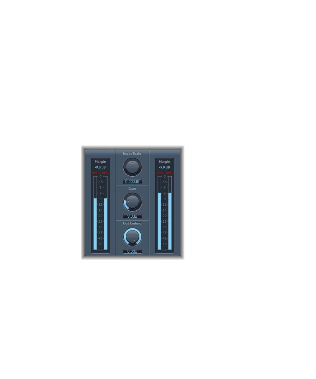
Adaptive Limiter
The Adaptive Limiter is a versatile tool for controlling the perceived loudness of sounds.
It works by rounding and smoothing peaks in the signal, producing an effect similar to
an analog amplifier being driven hard. Like an amplifier, it can slightly color the sound
of the signal. You can use the Adaptive Limiter to achieve maximum gain, without
introducing generally unwanted distortion and clipping, which can occur when the signal
exceeds 0 dBFS.
The Adaptive Limiter is typically used on the final mix, where it may be placed after a
compressor, such as the Multipressor, and before a final gain control, resulting in a mix
of maximum loudness. The Adaptive Limiter can produce a louder-sounding mix than
can be achieved by normalizing the signal.
Note: Using the Adaptive Limiter adds latency when the Lookahead parameter is active.
Usually it should be used on the entire clip sequence, which may be achieved by creating
a compound clip and applying the effect to that top-level clip.
• Input meters (to the left): Show the input levels in real time as the file or project plays.
The Margin field shows the highest input level. You can reset the Margin field by clicking
it.
• Input Scale knob and field: Scales the input level. Scaling is useful for handling very
high-level or low-level input signals. It essentially squeezes the higher and lower signal
levels into a range that allows the Gain knob to work effectively. In general, the input
level should never exceed 0 dBFS, which can result in unwanted distortion.
• Gain knob and field: Sets the amount of gain after input scaling.
65Chapter 4 Levels Effects
Page 66

• Out Ceiling knob and field: Sets the maximum output level, or ceiling. The signal will
not rise above this.
• Output meters (to the right): Show output levels, allowing you to see the results of the
limiting process. The Margin field shows the highest output level. You can reset the
Margin field by clicking it.
• Mode buttons (Extended Parameters area): Choose the type of peak smoothing:
• OptFit: Limiting follows a linear curve, which allows signal peaks above 0 dB.
• NoOver: Avoids distortion artifacts from the output hardware by ensuring that the
signal does not exceed 0 dB.
• Lookahead field and slider(Extended Parameters area): Adjusts how far ahead the Adaptive
Limiter analyzes the file for peaks.
• Remove DC checkbox (Extended Parameters area): Enable to activate a highpass filter
that removes direct current (DC) from the signal. DC can be introduced by lower-quality
audio hardware.
Compressor
The Compressor is designed to emulate the sound and response of a professional-level
analog (hardware) compressor. It tightens up your audio by reducing sounds that exceed
a certain threshold level, smoothing out the dynamics and increasing the overall
volume—the perceived loudness. Compression helps bring the key parts of an audio clip
into focus, while preventing softer parts from becoming inaudible. It is probably the most
versatile and widely used sound-shaping tool in professional mixing, next to EQ.
You can use the Compressor with individual clips, including voice, instrumental, and
effects clips.
66 Chapter 4 Levels Effects
Page 67
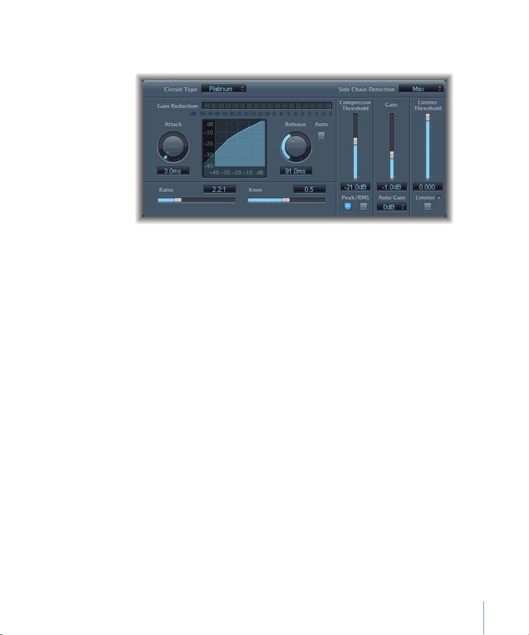
Compressor Parameters
The Compressor offers the following parameters:
• Circuit Type pop-up menu: Choose the type of circuit emulated by the Compressor. The
choices are Platinum, Class(ic) A_R, Class(ic) A_U, VCA, FET, and Opto (optical).
• Side Chain Detection pop-up menu: Determines if the Compressor uses the maximum
level of each side-chained signal (Max) or the summed level of all side-chained signals
(Sum) to exceed or fall below the threshold.
• If either of the stereo channels exceeds or falls below the threshold, both channels
are compressed.
• If Sum is chosen, the combined level of both channels must exceed the threshold
before compression occurs.
• Gain Reduction meter: Shows the amount of compression in real time.
• Attack knob and field: Determines the amount of time it takes for the Compressor to
react when the signal exceeds the threshold.
• Compression curve display: Shows the compression curve created by the combination
of Ratio and Knee parameter values. Input (level) is shown on the x-axis and output
(level) on the y-axis.
• Release knob and field: Determines the amount of time it takes for the Compressor to
stop reducing the signal after the signal level falls below the threshold.
• Auto button: When the Auto button is active, the release time dynamically adjusts to
the audio material.
• Ratio slider and field: Sets the compression ratio—the ratio of signal reduction when
the threshold is exceeded.
• Knee slider and field: Determines the strength of compression at levels close to the
threshold. Lower values result in more severe/immediate compression (hard knee).
Higher values result in gentler compression (soft knee).
67Chapter 4 Levels Effects
Page 68

• Compressor Threshold slider and field: Sets the threshold level—signals above this
threshold value are reduced in level.
• Peak/RMSbuttons: Determines whether signal analysis is with thePeak or RMSmethod,
when using the Platinum circuit type.
• Gain slider and field: Sets the amount of gain applied to the output signal.
• Auto Gain pop-up menu: Choose a value to compensate for volume reductions caused
by compression. The choices are Off, 0 dB, and −12 dB.
• Limiter Threshold slider and field: Sets the threshold level for the limiter.
• Limiter button: Turns the integrated limiter on or off.
• Output Distortion pop-up menu (Extended Parameters area): Choose whether to apply
clipping above 0 dB, and the type of clipping. Choices are: Off, Soft, Hard, and Clip.
• Activity pop-up menu (Extended Parameters area): Enables or disables the side chain.
Choices are: Off, Listen, and On.
• Mode pop-up menu (Extended Parameters area): Choose the type of filter used for the
side chain. Choices are: LP (lowpass), BP (bandpass), HP (highpass), ParEQ (parametric),
and HS (high shelving).
• Frequency slider and field (Extended Parameters area): Sets the center frequency for the
side-chain filter.
• Q slider and field (Extended Parameters area): Sets the width of the frequency band
affected by the side-chain filter.
• Gain slider and field (Extended Parameters area): Sets the amount of gain applied to the
side-chain signal.
• Mix slider and field (Extended Parameters area): Determines the balance between dry
(source) and wet (effect) signals.
Using the Compressor
The following section explains how to use the main Compressor parameters.
Setting the Compressor Threshold and Ratio
The most important Compressor parameters are Threshold and Ratio. The Threshold sets
the floor level in decibels. Signals that exceed this level are reduced by the amount set
as the Ratio.
The Ratio is a percentage of the overall level; the more the signal exceeds the threshold,
the more it is reduced. A ratio of 4:1 means that increasing the input by 4 dB results in
an increase of the output by 1 dB, if above the threshold.
As an example, with the Threshold set at −20 dB and the Ratio set to 4:1, a −16 dB peak
in the signal (4 dB louder than the threshold) is reduced by 3 dB, resulting in an output
level of −19 dB.
68 Chapter 4 Levels Effects
Page 69

Setting Suitable Compressor Envelope Times
The Attack and Release parameters shape the dynamic response of the Compressor. The
Attack parameter determines the time it takes after the signal exceeds the thresholdlevel
before the Compressor starts reducing the signal.
Many sounds, including voices and musical instruments, rely on the initial attack phase
to define the core timbre and characteristic of the sound. When compressing these types
of sounds, you should set higher Attack values to ensure that the attack transients of the
source signal aren’t lost or altered.
When attempting to maximize the level of an overall mix, it is best to set the Attack
parameter to a lower value, because higher values often result in no, or minimal,
compression.
The Release parameter determines how quickly the signal is restored to its original level
after it falls below the threshold level. Set a higher Release value to smooth out dynamic
differences in the signal. Set lower Release values if you want to emphasize dynamic
differences.
Important: The discussion above is highly reliant on not only the type of source material,
but also the compression ratio and threshold settings.
Setting the Compressor Knee
The Knee parameter determines whether the signal is slightly, or severely, compressed
as it approaches the threshold level.
Setting a Knee value close to 0 (zero) results in no compression of signal levels that fall
just below the threshold, while levels at the threshold are compressed by the full Ratio
amount. This is known as hard knee compression, which can cause abrupt and often
unwanted transitions as the signal reaches the threshold.
Increasing the Knee parameter value increases the amount of compression as the signal
approaches the threshold, creating a smoother transition. This is called soft knee
compression.
Setting Other Compressor Parameters
As the Compressor reduces levels, the overall volume at its output is typically lower than
the input signal. You can adjust the output level with the Gain slider.
You can also use the Auto Gain parameter to compensate for the level reduction caused
by compression (choose either −12 dB or 0 dB).
When you use the Platinum circuit type, the Compressor can analyze the signal using
one of two methods: Peak or root mean square (RMS). While Peak is more technically
accurate, RMS provides a better indication of how people perceive the signal loudness.
69Chapter 4 Levels Effects
Page 70
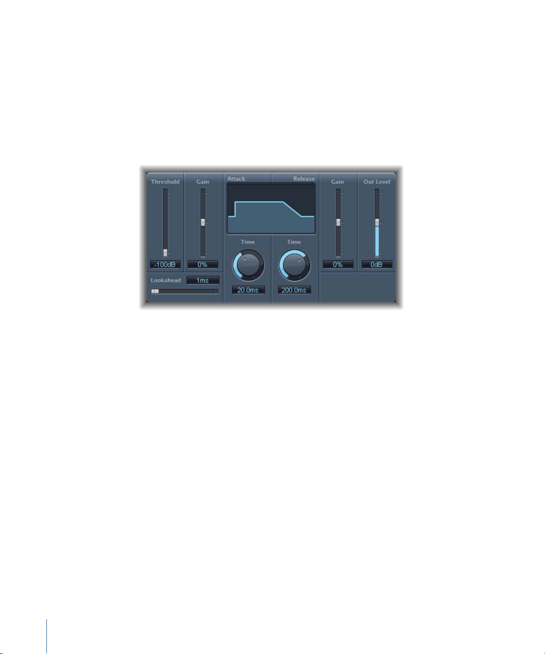
Note: If you activate Auto Gain and RMS simultaneously, the signal may become
over-saturated. If you hear any distortion, switch Auto Gain off and adjust the Gain slider
until the distortion is inaudible.
Enveloper
The Enveloper is an unusual processor that lets you shape the attack and release phases
of a signal—the signal’s transients, in other words. This makes it a unique tool that can
be used to achieve results that differ from other dynamic processors.
• Threshold slider and field: Sets the threshold level. Signals that exceed the threshold
have their attack and release phase levels altered.
• (Attack) Gain slider and field: Boosts or attenuates the attack phase of the signal. When
the Gain slider is set to the center position—0%—the signal is unaffected.
• Lookahead slider and field: Sets the pre-read analysis time for the incoming signal. This
enables the Enveloper to know in advance what signals are coming, enabling accurate
and fast processing.
• (Attack) Time knob and field: Determines the amount of time it takes for the signal to
increase from the threshold level to the maximum Gain level.
• Display: Shows the attack and release curves applied to the signal.
• (Release) Time knob and field: Determines the amount of time it takes for the signal to
fall from the maximum gain level to the threshold level.
• (Release) Gainslider and field: Boosts or attenuates the release phase of the signal. When
the Gain slider is set to the center position—0%—the signal is unaffected.
• Out Level slider and field: Sets the level of the output signal.
70 Chapter 4 Levels Effects
Page 71

Using the Enveloper
The most important parameters of the Enveloper are the two Gain sliders, one on each
side of the central display. These govern the Attack and Release levels of each respective
phase.
Boosting the attack phase can add snap to a drum sound, or it can amplify the initial
pluck or pick sound of a stringed instrument. Attenuating the attack causes percussive
signals to fade in more softly. You can also mute the attack, making it virtually inaudible.
A creative use for this effect is alteration of the attack transients to mask poor timing of
recorded instrument parts.
Boosting the release phase also accentuates any reverb applied to the affected clip.
Conversely, attenuating the release phase makes audio originally drenched in reverb
sound drier. This is particularly useful when working with drum loops, but it has many
other applications as well. Let your imagination be your guide.
When using the Enveloper, set the Threshold to the minimum value and leave it there.
Only when you seriously raise the release phase, which boosts the noise level of the
original recording, should you raise the Threshold slider a little. This limits the Enveloper
to affecting only the useful part of the signal.
Drastic boosting or cutting of either the release or attack phase may change the overall
level of the signal. You can compensate for this by adjusting the Out Level slider.
Generally, you’ll find that Attack Time values of around 20 ms and Release Time values
of 1500 ms are good to start with. Then adjust them for the type of signal that you’re
processing.
The Lookahead sliderdefines how far into the future of theincoming signal the Enveloper
looks, in order to anticipate future events. You generally won’t need to use this feature,
except when processing signals with extremely sensitive transients. If you do raise the
Lookahead value, you may need to adjust the Attack Time to compensate.
In contrast to a compressor or expander, the Enveloper operates independently of the
absolute level of the input signal—but this works only if the Threshold slider is set to the
lowest possible value.
71Chapter 4 Levels Effects
Page 72
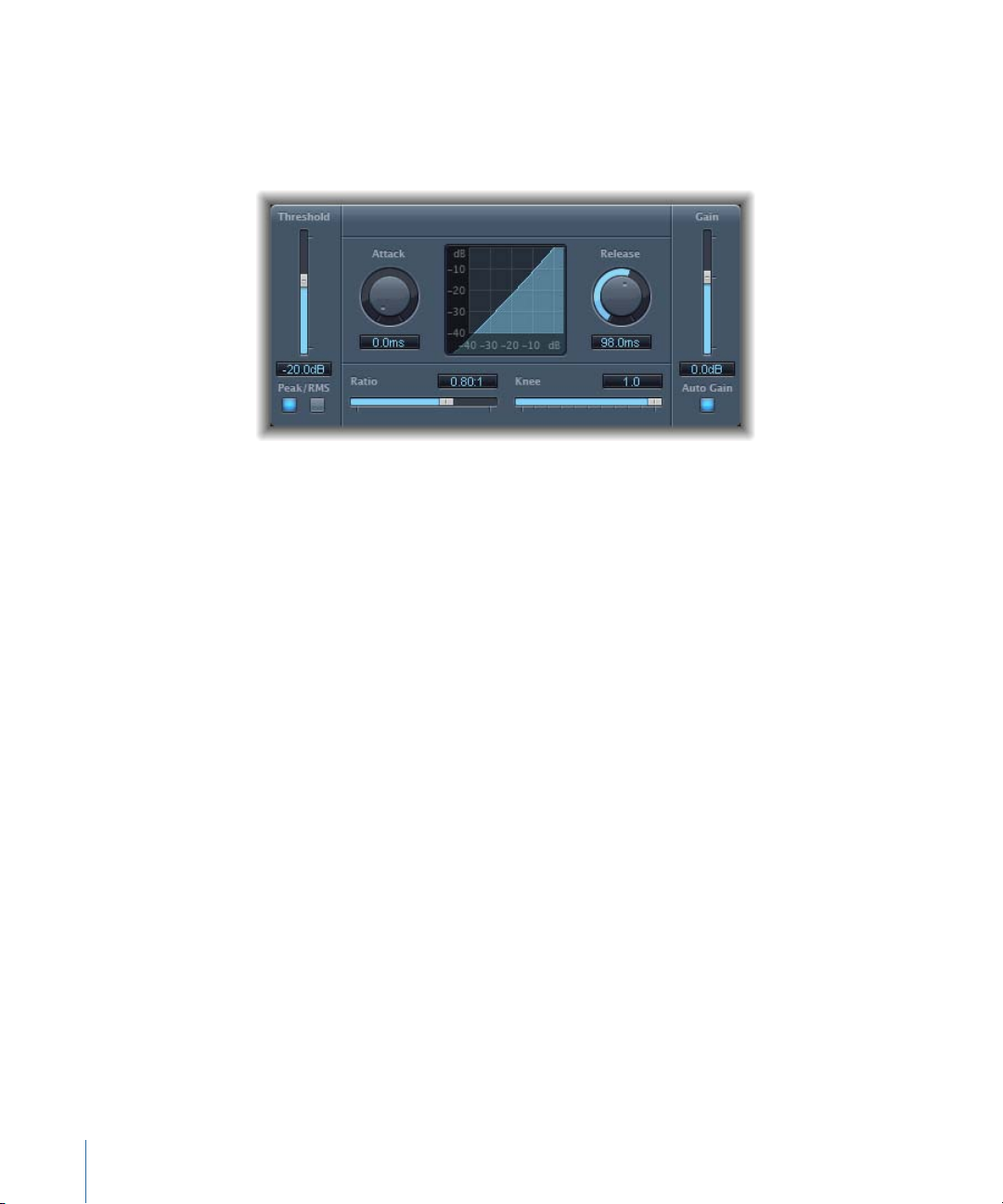
Expander
The Expander is similar in concept to a compressor, but increases, rather than reduces,
the dynamic range above the threshold level. You can use the Expander to add liveliness
and freshness to your audio signals.
• Threshold sliderand field: Sets the threshold level. Signals above this level are expanded.
• Peak/RMS buttons: Determine whether the Peak or RMS method is used to analyze the
signal.
• Attack knob and field: Determines the time it takes for the Expander to respond to
signals that exceed the threshold level.
• Expansion display: Shows the expansion curve applied to the signal.
• Release knob and field: Sets the time it takes for the Expander to stop processing the
signal after it falls below the threshold level.
• Ratio slider and field: Sets the expansion ratio—the ratio of signal expansion when the
threshold is exceeded.
Note: As the Expander is a genuine upward expander—in contrast to a downward
expander, which increases the dynamic range below the threshold—the Ratio slider
features a value range of 1:1 to 0.5:1.
• Knee slider and field: Determines the strength of expansion at levels close to the
threshold. Lower values result in more severe or immediate expansion—hard knee.
Higher values result in a gentler expansion—soft knee.
• Gain slider and field: Sets the amount of output gain.
• Auto Gain button: Compensates for the level increase caused by expansion. When
Auto Gain is active, the signal sounds softer, even when the peak level remains the
same.
Note: If you dramatically change the dynamics of a signal (with extreme Threshold and
Ratio values), you may need to reduce the Gain slider level to avoid distortion. In most
cases, turning on Auto Gain will adjust the signal appropriately.
72 Chapter 4 Levels Effects
Page 73
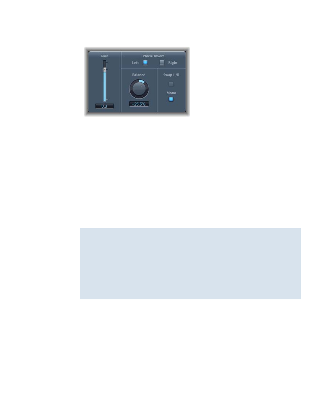
Gain Plug-in
Gain amplifies (or reduces) the signal by a specific decibel amount.
• Gain slider and field: Sets the amount of gain.
• Phase Invert Left and Right buttons: Invert the phase of the left and right channels,
respectively.
• Balance knob and field: Adjusts the balance of the incoming signal between the left
and right channels.
• Swap L/R (Left/Right) button: Swaps the left and right output channels. The swapping
occurs after the Balance parameter in the signal path.
• Mono button: Outputs the summed mono signal on both the left and right channels.
Note: The Gain plug-in is available in mono, mono to stereo, and stereo instances. In
mono and mono to stereo modes, only one Phase Invert button is available. In the mono
version, the Stereo Balance, Swap Left/Right, and Mono parameters are disabled.
Using Phase Inversion
Inverting phase is useful for dealing with time alignment problems, particularly those
caused by simultaneous recording with multiple microphones. When you invert the
phase of a signal heard in isolation, it sounds identical to the original. When the signal
is heard in conjunction with other signals, however, phase inversion may have an audible
effect. For example, if you place microphones above and below a snare drum, you may
find that inverting the phase of either microphone can improve (or ruin) the sound. As
always, rely on your ears.
Limiter
The Limiter works much like a compressor but with one important difference: where a
compressor proportionally reduces the signal when it exceeds the threshold, a limiter
reduces any peak above the threshold to the threshold level, effectively limiting the signal
to this level.
73Chapter 4 Levels Effects
Page 74

The Limiter is used primarily when mastering. Typically, you apply the Limiter as the very
last process in the mastering signal chain, where it raises the overall volume of the signal
so that it reaches, but does not exceed, 0 dB.
The Limiter is designed in such a way that if set to 0 dB Gain and 0 dB Output Level, it
has no effect on a normalized signal. If the signal clips, the Limiter reduces the level before
clipping can occur. The Limiter cannot, however, fix audio that is clipped during recording.
• Gain reduction meter: Shows the amount of limiting in real time.
• Gain slider and field: Sets the amount of gain applied to the input signal.
• Lookahead slider and field: Adjusts how far ahead in milliseconds the Limiter analyzes
the audio signal. This enables it to react earlier to peak volumes by adjusting the amount
of reduction.
Note: Lookahead causes latency, but this has no perceptible effect when you use the
Limiter as a mastering effect on prerecorded material. Set it to higher values if you
want the limiting effect to occur before the maximum level is reached, thus creating
a smoother transition.
• Release sliderand field: Sets the amount of time, after the signal falls below the threshold
level, before the Limiter stops processing.
• Output Level knob and field: Sets the output level of the signal.
• Softknee button: When active, the signal is limited only when it reaches the threshold.
The transition to full limiting is nonlinear, producing a softer, less abrupt effect, and
reducing distortion artifacts that can be produced by hard limiting.
74 Chapter 4 Levels Effects
Page 75

Multichannel Gain
Multichannel Gain allows you to independently control the gain (and phase) of each
channel in a surround mix.
• Master slider and field: Sets the master gain for the combined channel output.
• Channel gain sliders and fields: Set the amount of gain for the respective channel.
• Phase Invert buttons: Invert the phase of the selected channel.
• Mute buttons: Mute the selected channel.
Multipressor
The Multipressor (an abbreviation for multiband compressor) is an extremely versatile
audio mastering tool. It splits the incoming signal into different frequency bands—up to
four—and enables you to independently compress each band. After compression is
applied, the bands are combined into a single output signal.
The advantage of compressing different frequency bands separately is that it allows you
to apply more compression to the bands that need it, without affecting other bands. This
avoids the pumping effect often associated with high amounts of compression.
As the Multipressor allows the use of higher compression ratios on specific frequency
bands, it can achieve a higher average volume without causing audible artifacts.
Raising the overall volume level can result in a corresponding increase in the existing
noise floor. Each frequency band features downward expansion, which allows you to
reduce or suppress this noise.
75Chapter 4 Levels Effects
Page 76

Downward expansion works as a counterpart to compression. Whereas the compressor
Graphic display section
Frequency band section Output section
compresses the dynamic range of highervolume levels, the downward expander expands
the dynamic range of the lower volume levels. With downward expansion, the signal is
reduced in level when it falls below the threshold level. This works in a similar way to a
noise gate, but rather than abruptly cutting off the sound, it smoothly fades the volume
with an adjustable ratio.
Multipressor Parameters
The parameters in the Multipressor window are grouped into three main areas: the
graphic display in the upper section, the set of controls for each frequency band in the
lower section, and the output parameters on the right.
Multipressor Graphic Display Section
• Graphic display: Each frequency band is represented graphically. The amount of gain
change from 0 dB is indicated by blue bars. The band number appears in the center of
active bands. You can adjust each frequency band independently in the following ways:
• Drag the horizontal bar up or down to adjust the gain makeup for that band.
• Drag the vertical edges of a band to the left or right to set the crossover frequencies,
which adjusts the band’s frequency range.
• Crossover fields: Set the crossover frequency between adjacent bands.
• Gain Make-up fields: Set the amount of the gain make-up for each band.
76 Chapter 4 Levels Effects
Page 77

Multipressor Frequency Band Section
• Compr(ession) Thrsh(old) fields: Set the compression threshold for the selected band.
Setting the parameter to 0 dB results in no compression of the band.
• Compr(ession) Ratio fields: Set the compression ratio for the selected band. Setting the
parameter to 1:1 results in no compression of the band.
• Expnd Thrsh(old) fields: Set the expansion threshold for the selected band. Setting the
parameter to its minimum value (−60 dB) means that only signals that fall below this
level are expanded.
• Expnd Ratio fields: Set the expansion ratio for the selected band.
• Expnd Reduction fields: Set the amount of downward expansion for the selected band.
• Peak/RMS fields: Enter a smaller value for shorter peak detection, or a larger value for
RMS detection, in milliseconds.
• Attack fields: Set the amount of time before compression starts for the selected band,
after the signal exceeds the threshold.
• Release fields: Set the time required before compression stops on the selected band,
after the signal falls below the threshold.
• Band on/off buttons (1, 2, 3, and 4): Enable/disable each band (1 to 4). When enabled,
the button is highlighted, and the corresponding band appears in the graphic display
area above.
• Byp(ass) buttons: Enable to bypass the selected frequency band.
• Solo buttons: Enable to hear compression on only the selected frequency band.
• Level meters: The bar on the left shows the input level, and the bar on the right shows
the output level.
• Threshold arrows: Two arrows appear to the left of each Level meter.
• The upper arrow adjusts the Compression Threshold (Compr Thrsh).
• The lower arrow adjusts the Expansion Threshold (Expnd Thrsh).
Multipressor Output Section
• Auto Gain pop-up menu: When you choose On, it references the overall processing of
the signal to 0 dB, making the output louder.
• Lookahead value field: Adjusts how far the effect looks forward in the incoming audio
signal, in order to react earlier to peak volumes, and therefore achieve smoother
transitions.
• Out slider: Sets the overall gain at the Multipressor output.
• Level meter: Shows the overall output level.
77Chapter 4 Levels Effects
Page 78

Using the Multipressor
In the graphic display, the blue bars show the gain change—not merely the gain
reduction—as with a standard compressor. The gain change display is a composite value
consisting of the compression reduction, plus the expander reduction, plus the auto gain
compensation, plus the gain make-up.
Setting Multipressor Compression Parameters
The Compression Threshold and Compression Ratio parameters are the key parameters
for controlling compression. Usually the most useful combinations of these two settings
are a low Compression Threshold with a low Compression Ratio, or a high Compression
Threshold with a high Compression Ratio.
Setting Multipressor Downward Expansion Parameters
The Expansion Threshold, Expansion Ratio, and Expansion Reduction parameters are the
key parameters for controlling downward expansion. They determine the strength of the
expansion applied to the chosen range.
Setting Multipressor Peak/RMS and Envelope Parameters
Adjusting the parameter between Peak (0 ms, minimum value) and RMS (root mean
square −200 ms, maximum value) is dependent on the type of signal you want to
compress. An extremely short Peak detection setting is suitable for compression of short
and high peaks of low power, which do not typically occur in music. The RMS detection
method measures the power of the audio material over time and thus works much more
musically. This is because human hearing is more responsive to the overall power of the
signal than to single peaks. As a basic setting for most applications, the centered position
is recommended.
Setting Multipressor Output Parameters
The Out slider sets the overall output level. Set Lookahead to higher values when the
Peak/RMS fields are set to higher values (farther towards RMS). Set Auto Gain to On to
reference the overall processing to 0 dB, making the output louder.
Noise Gate
The Noise Gate is commonly used to suppress unwanted noise that is audible when the
audio signal is at a low level. You can use it to remove background noise, crosstalk from
other signal sources, and low-level hum, among other uses.
The Noise Gate works by allowing signals above the threshold level to pass unimpeded,
while reducing signals below the threshold level. This effectively removes lower-level
parts of the signal, while allowing the desired parts of the audio to pass.
78 Chapter 4 Levels Effects
Page 79

Noise Gate Parameters
The Noise Gate has the following parameters.
• Threshold slider and field: Sets the threshold level. Signals that fall below the threshold
will be reduced in level.
• Reduction slider and field: Sets the amount of signal reduction.
• Attack knob and field: Sets the amount of time it takes to fully open the gate after the
signal exceeds the threshold.
• Hold knob and field: Sets the amount of time the gate is kept open after the signal falls
below the threshold.
• Release knob and field: Sets the amount of time it takes to reach maximum attenuation
after the signal falls below the threshold.
• Hysteresis slider and field: Sets the difference (in decibels) between the threshold values
that open and close the gate. This prevents the gate from rapidly opening and closing
when the input signal is close to the threshold.
• Lookahead slider and field: Sets how far ahead the Noise Gate analyzes the incoming
signal, allowing the effect to respond more quickly to peak levels.
• Monitor button: Enable to hear the side-chain signal, including the effect of the High Cut
and Low Cut filters.
• High Cut slider and field: Sets the upper cutoff frequency for the side-chain signal.
• Low Cut slider and field: Sets the lower cutoff frequency for the side-chain signal.
Note: When no external side chain is selected, the input signal is usedas the side chain.
79Chapter 4 Levels Effects
Page 80

Using the Noise Gate
In most situations, setting the Reduction slider to the lowest possible value ensures that
sounds below the Threshold value are completely suppressed. Setting Reduction to a
higher value attenuates low-level sounds but still allows them to pass. You can also use
Reduction to boost the signal by up to 20 dB, which is useful for ducking effects.
The Attack, Hold, and Release knobs modify the dynamic response of the Noise Gate. If
you want the gate to open extremely quickly, for percussive signals such as drums, set
the Attack knob to a lower value. For sounds with a slow attack phase, such as string
pads, set Attack to a higher value. Similarly, when working with signals that fade out
gradually or that have longer reverb tails, set a higher Release knob value that allows the
signal to fade out naturally.
The Hold knob determines the minimum amount of time that the gate stays open. You
can use the Hold knob to prevent abrupt level changes—known as chattering—caused
by rapid opening or closing of the gate.
The Hysteresis slider provides another option for preventing chattering, without needing
to define a minimum Hold time. Use it to set the range between the threshold values
that open and close the Noise Gate. This is useful when the signal level hovers around
the Threshold level, causing the Noise Gate to switch on and off repeatedly, producing
the undesirable chattering effect. The Hysteresis slider essentially sets the Noise Gate to
open at the Threshold level and remain open until the level drops below another, lower,
level. As long as the difference between these two values is large enough to accommodate
the fluctuating level of the incoming signal, the Noise Gate can function without creating
chatter. This value is always negative. Generally, −6 dB is a good place to start.
In some situations, you may find that the level of the signal you want to keep and the
level of the noise signal are close, making it difficult to separate them. For example, when
you are recording a drum kit and using the Noise Gate to isolate the sound of the snare
drum, the hi-hat may also open the gate in many cases. To remedy this, use the side-chain
controls to isolate the desired trigger signal with the High Cut and Low Cut filters.
Important: The side-chain signal is used only as a detector/trigger in this situation. The
filters are used to isolate particular trigger signals in the side-chain source, but they have
no influence on the actual gated signal—the audio being routed through the Noise Gate.
To use the side-chain filters
1 Click the Monitor button to hear how the High Cut and Low Cut filters will affect the
incoming trigger signal.
2 Drag the High Cut slider to set the upper frequency. Trigger signals above this are filtered.
3 Drag the Low Cut slider to set the lower frequency. Trigger signals below this are filtered.
80 Chapter 4 Levels Effects
Page 81
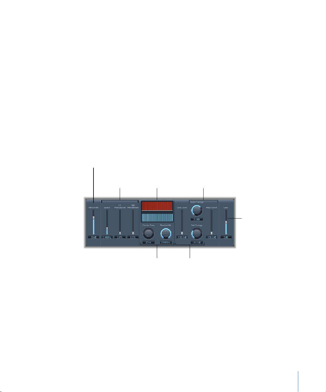
The filters allow only very high (loud) signal peaks to pass. In the drum kit example, you
Gain slider
Sub Energy and Low
Level controls
Center Freq. and
Bandwidth knobs
Speed, CF Modulation,
and BW Modulation
sliders Graphic display
Super Energy and High
Level controls
Threshold slider
could remove the hi-hat signal, which is higher in frequency, with the High Cut filter and
allow the snare signal to pass. Turn monitoring off to set a suitable Threshold level more
easily.
Spectral Gate
The Spectral Gate is an unusual filter effect that can be used as a tool for creative sound
design.
It works by dividing the incoming signal into two frequency ranges—above and below
a central frequency bandthat you specify withthe Center Freq and Bandwidth parameters.
The signal ranges above and below the defined band can be individually processed with
the Low Level and High Level parameters and the Super Energy and Sub Energy
parameters. See Using the Spectral Gate.
Spectral Gate Parameters
The Spectral Gate panel includes the following parameters:
• Threshold sliderand field: Sets the threshold level for division of frequency ranges. When
the threshold is exceeded, the frequency band defined by the Center Freq. and
Bandwidth parameters is divided into upper and lower frequency ranges.
• Speed slider and field: Sets the modulation frequency for the defined frequency band.
• CF (Center Frequency) Modulation slider and field: Sets the intensity of center frequency
modulation.
• BW (BandWidth) Modulationslider and field: Sets the amount of bandwidth modulation.
• Graphic display: Shows the frequency band defined by the Center Freq. and Bandwidth
parameters.
81Chapter 4 Levels Effects
Page 82

• Center Freq. (Frequency) knob and field: Sets the center frequency of the band that you
want to process.
• Bandwidth knob and field: Sets the width of the frequency band that you want to
process.
• Super Energy knob and field: Controls the level of the frequency range above the
threshold.
• High Level slider and field: Blends the frequencies of the original signal—above the
selected frequency band—with the processed signal.
• Sub Energy and field: Controls the level of the frequency range below the threshold.
• Low Level slider and field: Blends the frequencies of the original signal—below the
selected frequency band—with the processed signal.
• Gain slider and field: Sets the output level of the Spectral Gate.
Using the Spectral Gate
One way to familiarize yourself with the operation of the Spectral Gate would be to start
with a drum loop. Set the Center Freq. to its minimum (20 Hz) and the Bandwidth to its
maximum (20,000 Hz) value so that the entire frequency range is processed. Turn up the
Super Energy and Sub Energy knobs, one at a time, then try different Threshold settings.
This should give you a good sense of how different Threshold levels affect the sound of
Super Energy and Sub Energy. When you come across a sound that you like or consider
useful, narrow the Bandwidth drastically, gradually increase the Center Freq., and then
use the Low Level and High Level sliders to mix in some treble and bass from the original
signal. At lower Speed settings, turn up the CF Mod. or BW Mod. knobs.
Follow these steps to acquaint yourself with the Spectral Gate
1 Set the frequency band you want to process by using the Center Freq. and Bandwidth
parameters.
The graphic display visually indicates the band defined by these two parameters.
2 After the frequency band is defined, use the Threshold parameter to set the appropriate
level.
All incoming signals above and below the threshold level are divided into upper and
lower frequency ranges.
3 Use the Super Energy knob to control the level of the frequencies above the Threshold,
and use the Sub Energy knob to control the level of the frequencies below the Threshold.
4 You can mix the frequencies that fall outside the frequency band (defined by the Center
Freq. and Bandwidth parameters) with the processed signal.
a Use the Low Level slider to blend the frequencies below the defined frequency band
with the processed signal.
82 Chapter 4 Levels Effects
Page 83

b Use the High Level slider to blend frequencies above the defined frequency band with
the processed signal.
5 You can modulate the defined frequency band using the Speed, CF Modulation, and BW
Modulation parameters.
a Speed determines the modulation frequency.
b CF (Center Frequency) Modulation defines the intensity of the center frequency
modulation.
c BW (Band Width) Modulation controls the amount of bandwidth modulation.
6 After making your adjustments, you can use the Gain slider to adjust the final output
level of the processed signal.
Surround Compressor
The Surround Compressor, based on the Compressor, is specifically designed for
compression of complete surround mixes. It is commonly inserted in a surround clip that
carries multichannel audio.
You can adjust the compression ratio, knee, attack, and release for the main, side, surround,
and LFE channels, depending on the chosen surround format. All channels include an
integrated limiter and provide independent threshold and output level controls.
83Chapter 4 Levels Effects
Page 84
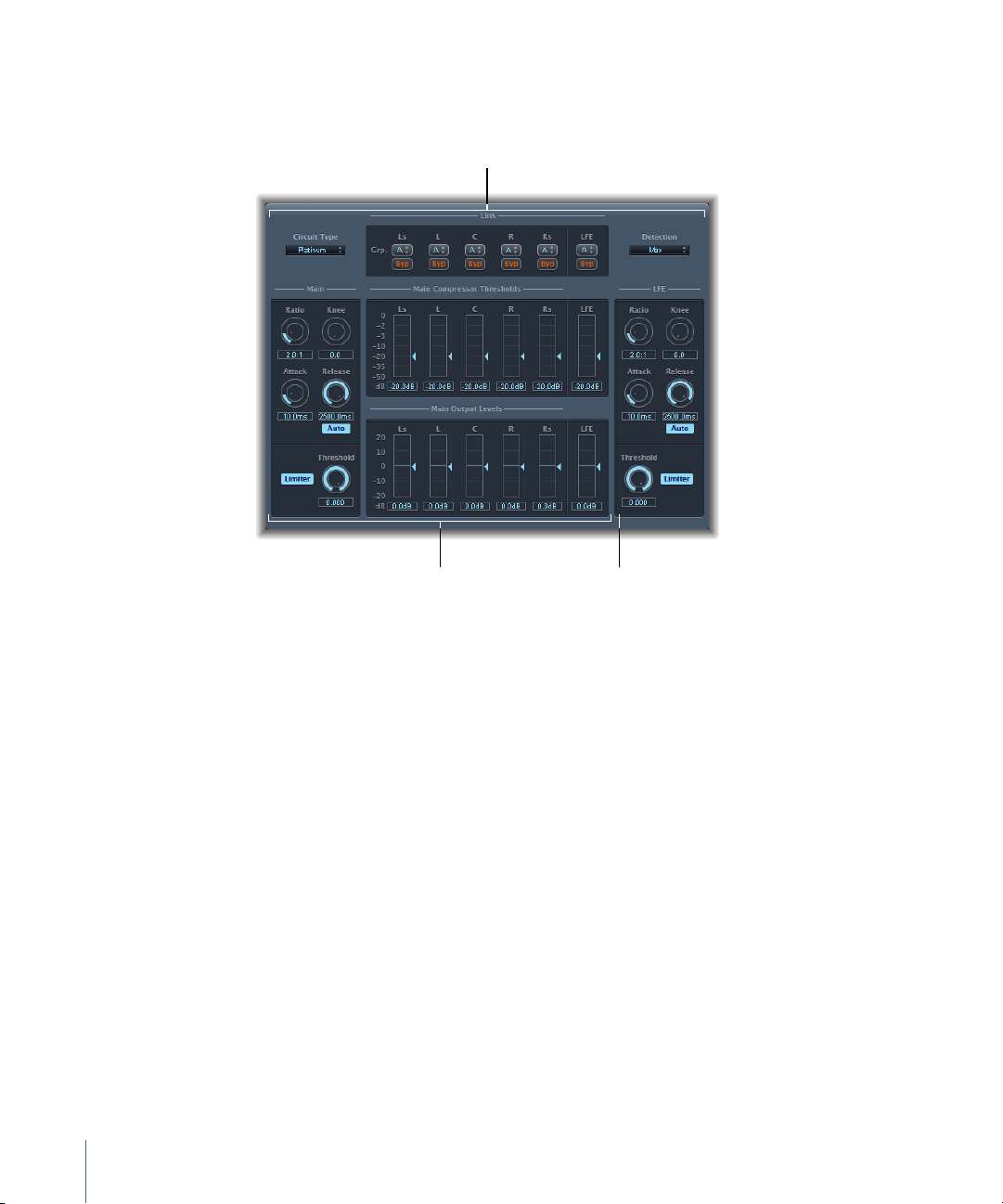
You can link channels by assigning them to one of three groups. When you adjust the
LFE sectionMain section
Link section
threshold or output parameter of any grouped channel, the parameter adjustment is
mirrored by all channels assigned to the group.
The Surround Compressor is divided into three sections:
• The Link section at the top contains a series of menus where you assign each channel
to a group. See Surround Compressor Link Parameters.
• The Main section includes controls common to all the main channels, and the threshold
and output controls for each channel. See Surround Compressor Main Parameters.
• The LFE section on the lower right includes separate controls for the LFE channel. See
Surround Compressor LFE Parameters.
84 Chapter 4 Levels Effects
Page 85
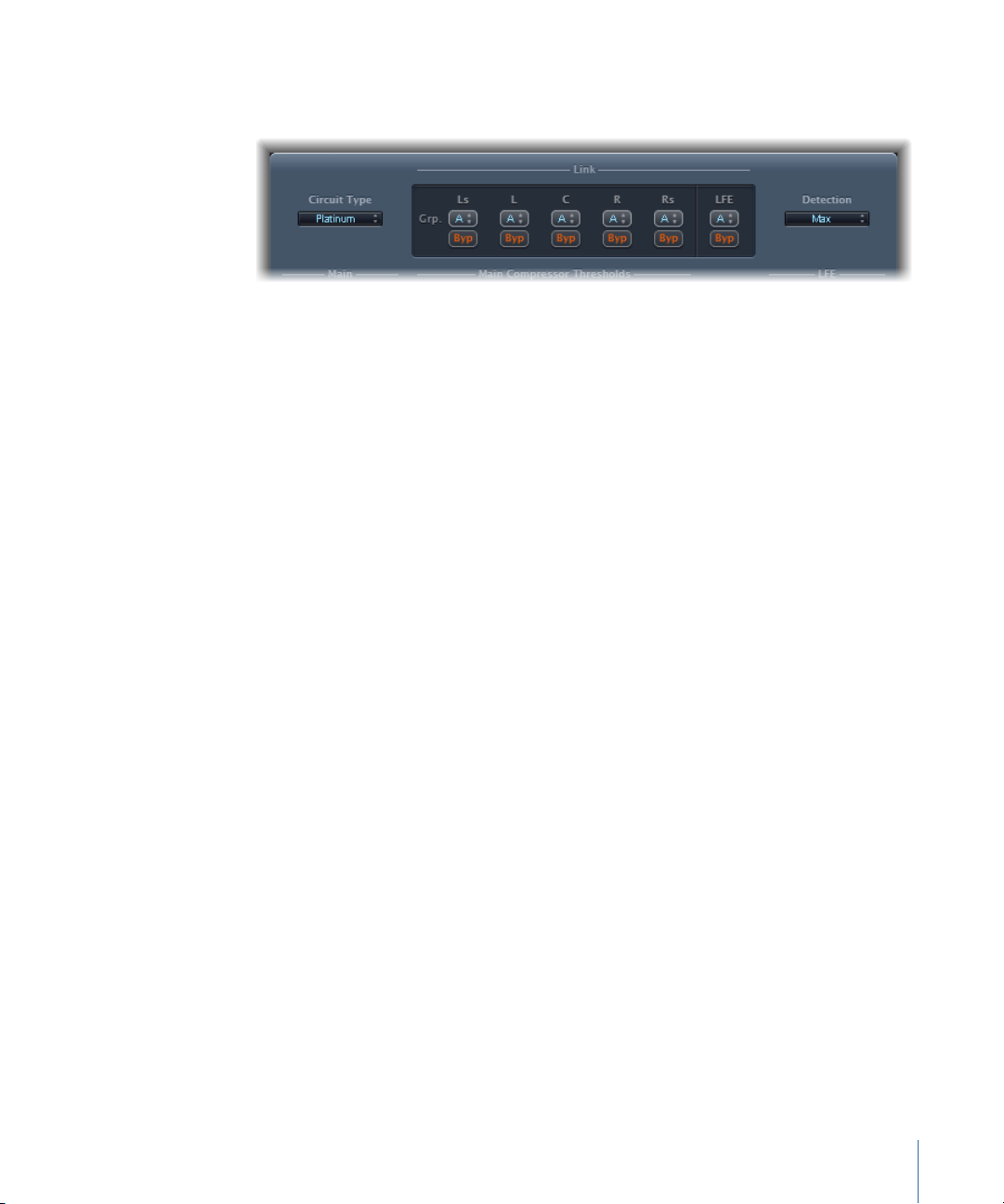
Surround Compressor Link Parameters
The Surround Compressor’s Link section provides the following parameters:
• Circuit Type pop-up menu: Choose the type of circuit emulated by the Surround
Compressor. The choices are Platinum, Classic A_R, Classic A_U, VCA, FET, and Opto
(optical).
• Grp. (Group) pop-up menus: Set group membership for each channel (A, B, C, or no
group (indicated by -). Moving the Threshold or Output Level slider for any grouped
channel will move the sliders for all channels assigned to that group.
Tip: Press Command and Option while moving the Threshold or Output Level slider
of a grouped channel to temporarily unlink the channel from the group. This allows
you tomake independent threshold settings while maintainingthe side-chain detection
link necessary for a stable surround image.
• Byp (Bypass) buttons: Independently bypasses the corresponding channel unless
grouped. If the channel belongs to a group, all channels in the group are bypassed.
• Detection pop-up menu: Determines if the Surround Compressor uses the maximum
level of each signal (Max) or the summed level of all signals (Sum) to exceed or fall
below the threshold.
• If Max is chosen, and any of the surround channels exceeds or falls below the
Threshold, that channel (or grouped channels) is compressed.
• If Sum is chosen, the combined level of all channels must exceed the Threshold
before compression occurs.
85Chapter 4 Levels Effects
Page 86
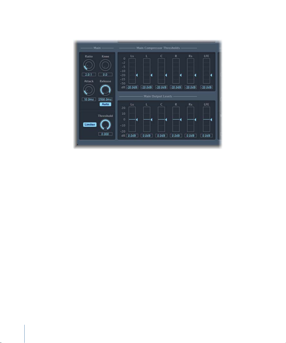
Surround Compressor Main Parameters
The Surround Compressor’s Main section provides the following parameters:
• Ratio knob and field: Sets the ratio of signal reduction when the threshold is exceeded.
• Knee knoband field: Determines the ratio of compression at levels close to the threshold.
• Attack knob and field: Sets the amount of time it takes to reach full compression, after
the signal exceeds the threshold.
• Release knob and field: Sets the amount of time it takes to return to 0 compression,
after the signal falls below the threshold.
• Auto button: When the Auto button is enabled, the release time dynamically adjusts
to the audio material.
• Limiter button: Turns limiting for the main channels on or off.
• Threshold knob and field: Sets the threshold for the limiter on the main channels.
• Main Compressor Threshold sliders and fields: Set the threshold level for each
channel—including the LFE channel, which also has independent controls.
• Main Output Levels sliders and fields: Set the output level for each channel—including
the LFE channel, which has independent controls.
86 Chapter 4 Levels Effects
Page 87
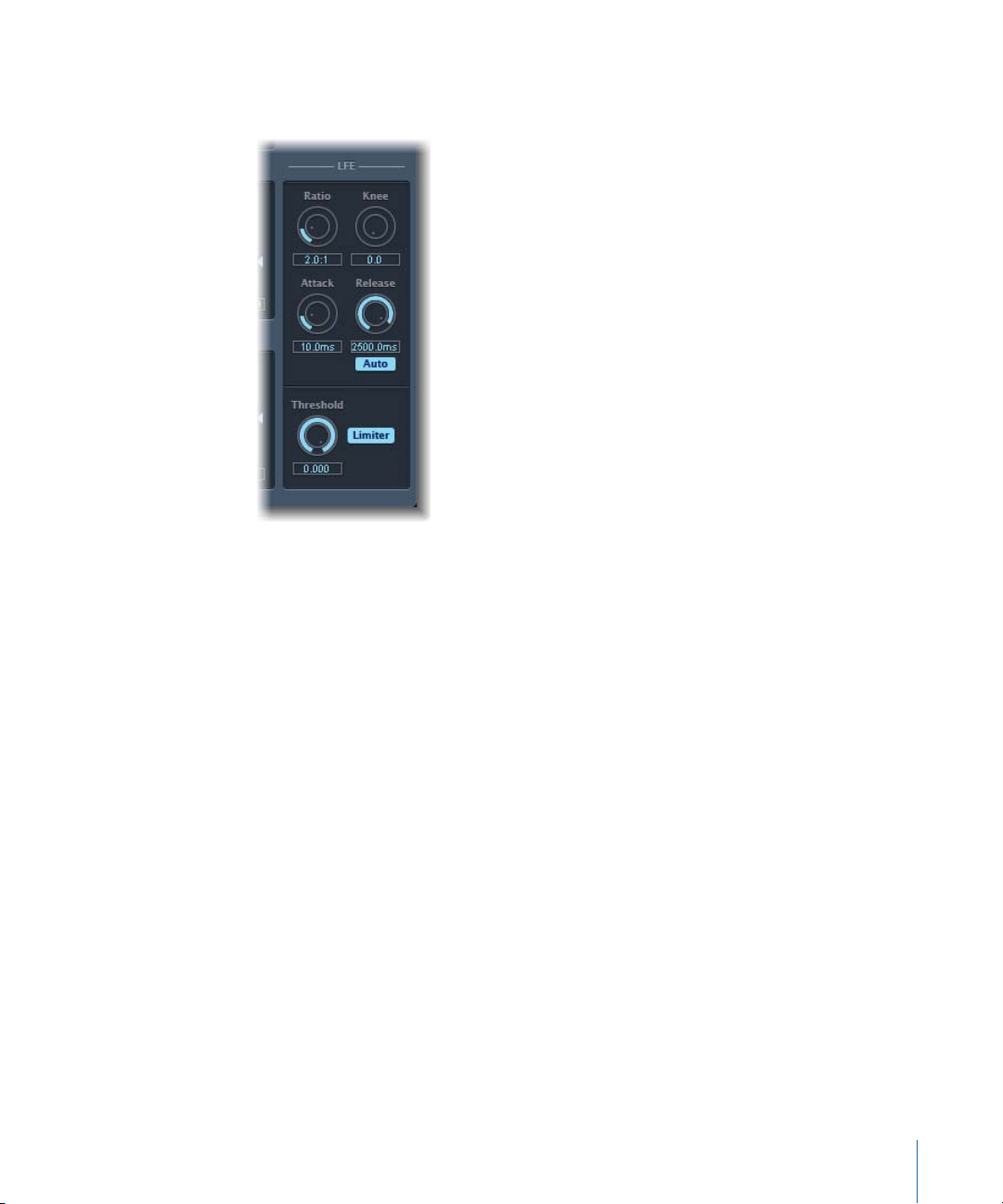
Surround Compressor LFE Parameters
The Surround Compressor’s LFE section provides the following parameters:
• Ratio knob and field: Sets the compression ratio for the LFE channel.
• Knee knob and field: Sets the knee for the LFE channel.
• Attack knob and field: Sets the attack time for the LFE channel.
• Release knob and field: Sets the release time for the LFE channel.
• Auto button: When the Auto button is enabled, the release time automatically adjusts
to the audio signal.
• Threshold knob and field: Sets the threshold for the limiter on the LFE channel.
• Limiter button: Enables and disables limiting for the LFE channel.
87Chapter 4 Levels Effects
Page 88

Page 89

Modulation Effects
5
Modulation effects are used to add motion and depth to your sound.
Effects such as chorus, flanging, and phasing are well-known examples. Modulation effects
typically delay the incoming signal by a few milliseconds and use an LFO to modulate
the delayed signal. The LFO may also be used to modulate the delay time in some effects.
A low frequency oscillator (LFO) is much like the sound-generating oscillators in
synthesizers, but the frequencies generated by an LFO are so low that they can’t beheard.
Therefore, they are used only for modulation purposes. LFO parameters include speed
(or frequency) and depth—also called intensity—controls.
You can also control the ratio of the affected (wet) signal and the original (dry) signal.
Some modulation effects include feedback parameters, which add part of the effect’s
output back into the effect input.
Other modulation effects involve pitch. The most basic type of pitch modulation effect
is vibrato. It uses an LFO to modulate the frequency of the sound. Unlike other pitch
modulation effects, vibrato alters only the delayed signal.
More complex Final Cut Pro modulation effects, such as Ensemble, mix several delayed
signals with the original signal.
This chapter covers the following:
• Chorus Effect (p. 90)
• Ensemble Effect (p. 90)
• Flanger Effect (p. 92)
• Phaser Effect (p. 93)
• Scanner Vibrato Effect (p. 94)
• Tremolo Effect (p. 96)
89
Page 90

Chorus Effect
The Chorus effect delays the original signal. The delay time is modulated with an LFO.
The delayed, modulated signal is mixed with the original, dry signal.
You can use the Chorus effect to enrich the incoming signal and create the impression
that multiple instruments or voices are being played in unison. The slight delay time
variations generated by the LFO simulate the subtle pitch and timing differences heard
when several musicians or vocalists perform together. Using chorus also adds fullness or
richness to the signal, and it can add movement to low or sustained sounds.
• Intensity slider and field: Sets the modulation amount.
• Rate knob and field: Defines the frequency, and therefore the speed, of the LFO.
• Mix slider and field: Determines the balance of dry and wet signals.
Ensemble Effect
The Ensemble combines up to eight chorus effects. Two standard LFOs and one random
LFO (which generates random modulations) enable you to create complex modulations.
The Ensemble’s graphic display visually represents what is happening with the processed
signals.
90 Chapter 5 Modulation Effects
Page 91

The Ensemble effect can add a great dealof richness and movement to sounds, particularly
when you use a high number of voices. It is very useful for thickening parts, but it can
also be used to emulate more extreme pitch variations between voices, resulting in a
detuned quality to processed material.
• Intensity sliders and fields: Set the amount of modulation for each LFO.
• Rate knobs and fields: Control the frequency of each LFO.
• Voices slider and field: Determines how many individual chorus instances are used and,
therefore, how many voices, or signals, are generated in addition to the original signal.
• Graphic display: Indicates the shape and intensity of the modulations.
• Phase knob and field: Controls the phase relationship between the individual voice
modulations. The value you choose here is dependent on the number of voices, which
is why it is shown as a percentage value rather than in degrees. The value 100 (or −100)
indicates the greatest possible distance between the modulation phases of all voices.
• Spread sliderand field: Distributes voices across the stereo or surround field. Set a value
of 200% to artificially expand the stereo or surround base. Note that monaural
compatibility may suffer if you choose to do this.
• Mix slider and field: Determines the balance between dry and wet signals.
• Effect Volume knob and field: Determines the level of the effects signal. This is a useful
tool that compensates for changes in volume caused by changes to the Voices
parameter.
91Chapter 5 Modulation Effects
Page 92

Note: When youare using theEnsemble effect in surround, the input signal is converted
to mono before processing. In other words, you insert the Ensemble effect as a
multi-mono instance.
Flanger Effect
The Flanger effect works in much the same way as the Chorus effect, but it uses a
significantly shorter delay time. In addition, the effect signal can be fed back into the
input of the delay line.
Flanging is typically used to create changes that are described as adding a spacey or
underwater quality to input signals.
• Feedbackslider andfield: Determines the amount of theeffect signal that is routed back
into the input. This can change the tonal color and/or make the sweeping effect more
pronounced. Negative Feedback values invert the phase of the routed signal.
• Rate knob and field: Defines the frequency (the speed) of the LFO.
• Intensity slider and field: Determines the modulation amount.
• Mix slider and field: Determines the balance between dry and wet signals.
92 Chapter 5 Modulation Effects
Page 93

Phaser Effect
The Phaser effect combines the original signal with a copy that is slightly out of phase
with the original. This means that the amplitudes of the two signals reach their highest
and lowest points at slightly different times. The timing differences between the two
signals are modulated by two independent LFOs. In addition, the Phaser includes a filter
circuit and a built-in envelope follower that tracks volume changes in the input signal,
generating a dynamic control signal. This control signal alters the sweep range. Sonically,
phasing is used to create whooshing, sweeping sounds that wanderthrough the frequency
spectrum. It is a commonly used guitar effect, but it is suitable for a range of signals.
Phaser Feedback Section
• Filter button: Activates the filter section, which processes the feedback signal.
• LP and HP knobs and fields: Set the cutoff frequency of the filter section’s lowpass (LP)
and highpass (HP) filters.
• Feedbackslider andfield: Determines the amount of theeffect signal that is routed back
into the input of the effect.
Phaser Sweep Section
• Ceiling and Floor sliders and fields: Use the individual slider handles to determine the
frequency range affected by the LFO modulations.
• Order slider and field: Allows you to choose between different phaser algorithms. The
more orders a phaser has, the heavier the effect.
The 4, 6, 8, 10, and 12 settings put five different phaser algorithms at your fingertips.
All are modeled on analog circuits, with each designed for a specific application.
You are free to select odd-numbered settings (5, 7, 9, 11), which, strictly speaking, don’t
generate actual phasing. The more subtle comb filtering effects produced by
odd-numbered settings can, however, come in handy on occasion.
• Env Follow slider and field: Determines the impact of incoming signal levels on the
frequency range (as set with the Ceiling and Floor controls).
93Chapter 5 Modulation Effects
Page 94

Phaser LFO Section
• LFO 1 and LFO 2 Rate knobs and fields: Set the speed for each LFO.
• LFO Mix slider and fields: Determines the ratio between the two LFOs.
• Env Follow sliderand field: Determines the impact of incoming signal levels on the speed
of LFO 1.
• Phase knob and field: Available only in stereo and surround instances. Controls the
phase relationship between the individual channel modulations.
At 0°, the extreme valuesof the modulation are achieved simultaneously for all channels.
180° or −180° is equal to the greatest possible distance between the modulation phases
of the channels.
• Distribution pop-up menu: Available only in surround instances. Defines how the phase
offsets between the individual channels are distributed in the surround field. You can
choose from “circular,” “left↔right,” “front↔rear,” “random,” and “new random”
distributions.
Note: When you load a setting that uses the “random” option, the saved phase offset
value isrecalled. If you want to randomize the phase setting again, choose “new random”
in the Distribution pop-up menu.
Phaser Output Section
• Output Mix slider and field: Determines the balance of dry and wet signals. Negative
values result in a phase-inverted mix of the effect and direct (dry) signal.
• Warmth button: Enables a distortion circuit, suitable for warm overdrive effects.
Scanner Vibrato Effect
Scanner Vibrato simulates the scanner vibrato section of a Hammond organ. The Scanner
Vibrato is based on an analog delay line, consisting of several lowpass filters. The delay
line is scanned by a multipole capacitor, which has a rotating pickup. It is a unique effect
that cannot be simulated with simple LFOs.
94 Chapter 5 Modulation Effects
Page 95

You can choose between three different vibrato and chorus types. The stereo version of
The stereo parameters of
the mono version of the
Scanner Vibrato are
hidden behind a
transparent cover.
the effect features two additional parameters—Stereo Phase and Rate Right. These allow
you to set the modulation speed independently for the left and right channels.
• Vibrato knob: Use to choose from three Vibrato positions (V1, V2, and V3) or three
Chorus positions (C1, C2, and C3).
• In the Vibrato positions, only the delay line signal is heard, each with different
intensities.
• The three Chorus positions (C1, C2, and C3) mix the signal of the delay line with the
original signal. Mixing a vibrato signal with an original, statically pitched signal results
in a chorus effect. This organ-style chorus sounds different from the Final Cut Pro
Chorus plug-in.
• If the C0 setting is chosen, neither the chorus nor vibrato is enabled.
• Chorus Int knob: Sets the intensity of a chosen chorus effect type. If a vibrato effect
type is chosen, this parameter has no effect.
• Stereo Phase knob: When set to a value between 0° and 360°, Stereo Phase determines
the phase relationship between left and right channel modulations, thus enabling
synchronized stereo effects.
If you set the knob to “free,” you can set the modulation speed of the left and right
channel independently.
• Rate Left knob: Sets the modulation speed of the left channel when Stereo Phase is set
to “free.” If Stereo Phase is set to a value between 0° and 360°, Rate Left sets the
modulation speed for both the left and right channels. Rate Right has no function when
in this mode.
• Rate Right knob: Sets the modulation speed of the right channel when Stereo Phase is
set to “free.”
95Chapter 5 Modulation Effects
Page 96
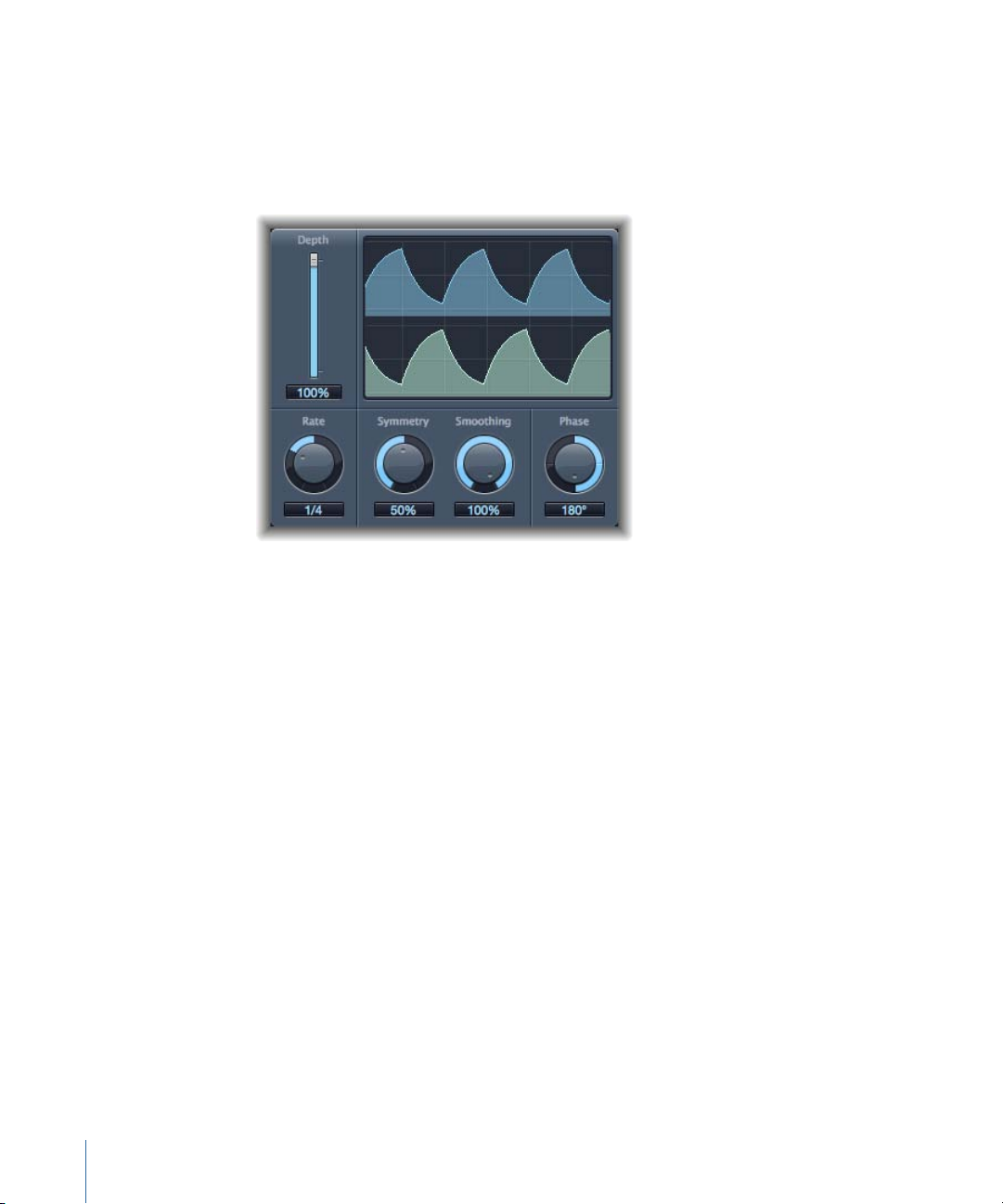
Tremolo Effect
The Tremolo effect modulates the amplitude of the incoming signal, resulting in periodic
volume changes. You’ll recognize this effect from vintage guitar combo amps (where it
is sometimes incorrectly referred to as vibrato). The graphic display shows all parameters,
except Rate.
• Depth slider and field: Determines the modulation amount.
• Waveform display: Shows the resulting waveform.
• Rate knob and field: Sets the frequency of the LFO.
• Symmetry and Smoothing knobs and fields: Use these to alter the shape of the LFO
waveform.
If Symmetry is set to 50% and Smoothing to 0%, the LFO waveform has a rectangular
shape. This means that the timing of the highest and lowest volume signals is equal,
with the switch between both states occurring abruptly.
• Phase knob and field: Available only in stereo and surround instances. Controls the
phase relationship between the individual channel modulations. At 0, modulation
values are reached simultaneously for all channels. Values of 180 or −180 indicate the
greatest possible distance between the modulation phases of the channels.
• Distribution pop-up menu: Available only in surround instances. Defines how phase
offsets between individual channels are distributed in the surround field. You can
choose from “circular,” “left↔right,” “front↔rear,” “random,” and “new random”
distributions (to randomize the phase, choose “new random”).
• Offset slider and field (Extended Parameters area): Sets the amount that the modulation
(cycle) is shifted to the left or right, resulting in subtle or significant tremolo variations.
96 Chapter 5 Modulation Effects
Page 97
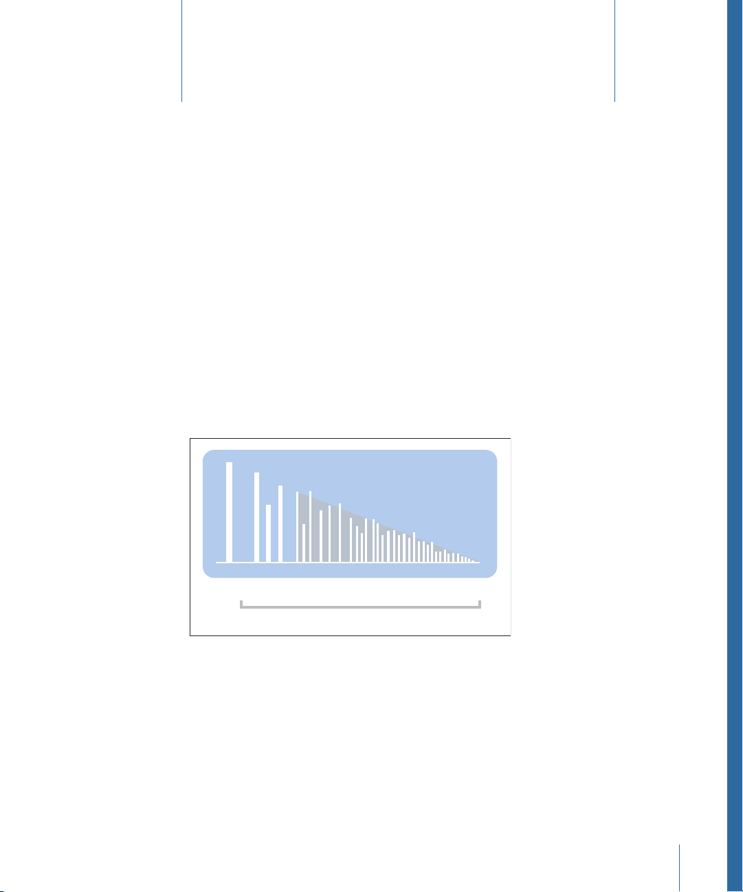
Signal
Discrete
reflections
Diffuse reverb tail
Reflection pattern/reverberation
Time
Spaces Effects
6
You can use spaces effects to simulate the sound of acoustic environments such as rooms,
concert halls, caverns, or an open space.
Sound waves repeatedly bounce off the surfaces—walls, ceilings, windows, and soon—of
any space, or off objects within a space, gradually dying out until they are inaudible.
These bouncing sound waves result in a reflection pattern, more commonly known as a
reverberation (or reverb).
The starting portion of a reverberation signal consists of a number of discrete reflections
that you can clearly discern before the diffuse reverb tail builds up. These early reflections
are essential in human perception of spatial characteristics, such as the size and shape
of a room.
This chapter covers the following:
• Plates, Digital Reverb Effects, and Convolution Reverb (p. 98)
• PlatinumVerb (p. 99)
97
Page 98

Plates, Digital Reverb Effects, and Convolution Reverb
The first form of reverb used in music production was actually a special room with hard
surfaces, called an echo chamber. It was used to add echoes to the signal. Mechanical
devices, including metal plates and springs, were also used to add reverberation to the
output of musical instruments and microphones.
Digital recording introduced digital reverb effects, which consist of thousands of delays
of varying lengths and intensities. The time differences between the original signal and
the arrival of the early reflections can be adjusted by a parameter commonly known as
predelay. The average number of reflections in a given period of time is determined by
the density parameter. The regularity or irregularity of the density is controlled with the
diffusion parameter.
Today’s computers make it possible to sample the reverb characteristics of real spaces,
using convolution reverbs. These room characteristic sample recordings are known as
impulse responses.
Convolution reverbs work by convolving (combining) an audio signal with the impulse
response recording of a room’s reverb characteristics. Final Cut Pro includes a Logic
convolution reverb called Space Designer. See Space Designer Convolution Reverb.
98 Chapter 6 Spaces Effects
Page 99
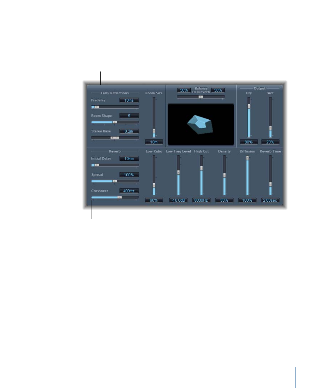
PlatinumVerb
Balance ER/Reverb slider
Early Reflections parameters
Output parameters
Reverb parameters
The PlatinumVerb allows you to edit both the early reflections and diffuse reverb tail
separately, making it easy to precisely emulate real rooms. Its dual-band Reverb section
splits the incoming signal into two bands, each of which is processed and can be edited
separately.
The interface is broken down into four parameter areas:
• Early Reflectionsparameters: Emulates the original signal’s first reflections as they bounce
off the walls, ceiling, and floor of a natural room. See PlatinumVerb Early Reflections
Parameters.
• Reverb parameters: Controls the diffuse reverberations. See PlatinumVerb Reverb
Parameters.
• Output parameters: Determines the balance between the effected (wet) and direct (dry)
signals. See PlatinumVerb Output Parameters.
• Balance ER/Reverb slider: Controls the balance between the Early Reflections and Reverb
sections. When you set the slider to either of its extreme positions, the unused section
is deactivated.
99Chapter 6 Spaces Effects
Page 100
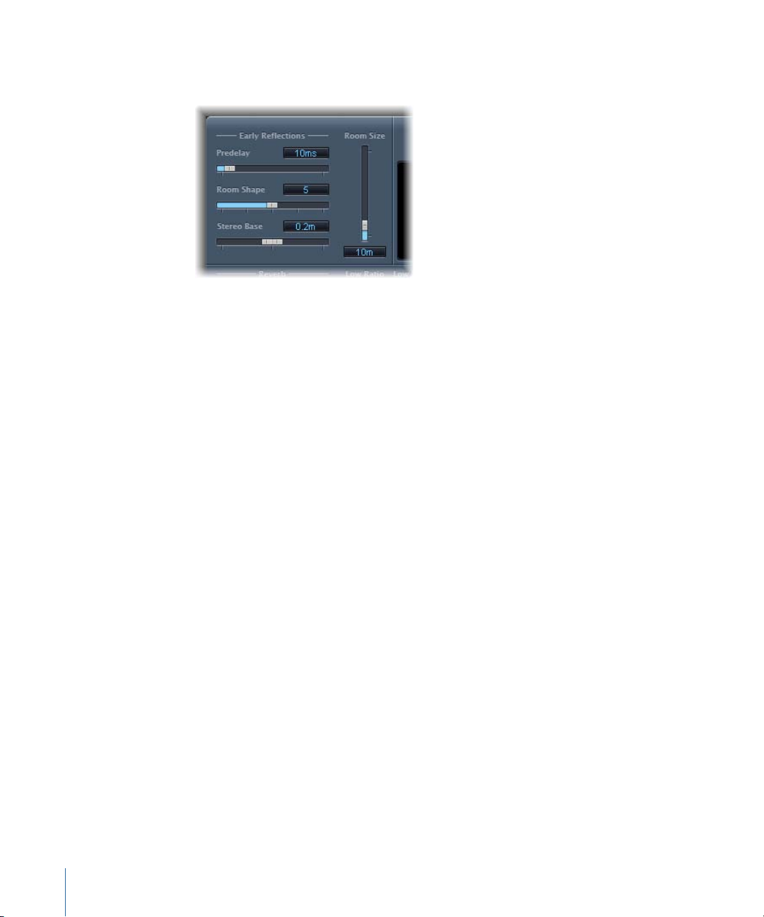
PlatinumVerb Early Reflections Parameters
The PlatinumVerb offers the following Early Reflections parameters:
• Predelay slider and field: Determines the amount of time between the start of the original
signal and the arrival of the early reflections. Extremely short Predelay settings can
color the sound and make it difficult to pinpoint the position of the signal source. Overly
long Predelay settings can be perceived as an unnatural echo and can divorce the
original signal from its early reflections, leaving an audible gap between them.
The optimum Predelay setting depends on the type of input signal—or more precisely,
the envelope of the input signal. Percussive signals generally require shorter predelays
than signals where the attack fades in gradually. A good working method is to use the
longest possible Predelay value before you start to hear undesirable side effects, such
as an audible echo. When you reach this point, reduce the Predelay setting slightly.
• Room Shapeslider and field: Defines the geometric form of the room. The numeric value
(3 to 7) represents the number of corners in the room. The graphic display visually
represents this setting.
• Room Size slider and field: Determines the dimensions of the room. The numeric value
indicates the length of the room’s walls—the distance between two corners.
• Stereo Base slider and field: Defines the distance between the two virtual microphones
that are used to capture the signal in the simulated room.
Note: Spacing the microphones slightly farther apart than the distance between two
human ears generally delivers the best, and most realistic, results. This parameter is
available only in stereo instances of the effect.
• ER Scale slider and field (Extended Parameters area): Scales the early reflections along
the time axis, influencing the Room Shape, Room Size, and Stereo Base parameters
simultaneously.
100 Chapter 6 Spaces Effects
 Loading...