

Page 1
K
Service Source
External Hard Drive SC
Page 2

K
Service Source
Exploded V ie w
External Hard Drive SC
Page 3

Exploded View 1
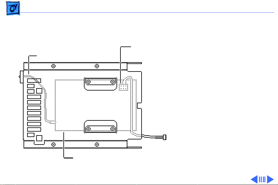
Exploded View
Cover
HDA-to-Case Cable
LED Cable Assembly
Hard Drive Mechanism
Fan Frame
Fan
SCSI Select Switch
SCSI Select Switch Cable
Power Supply
Page 4

K
Service Source
T ak e Apart
External Hard Drive SC
Page 5
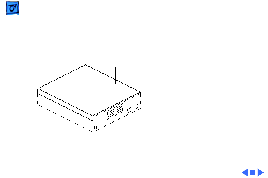
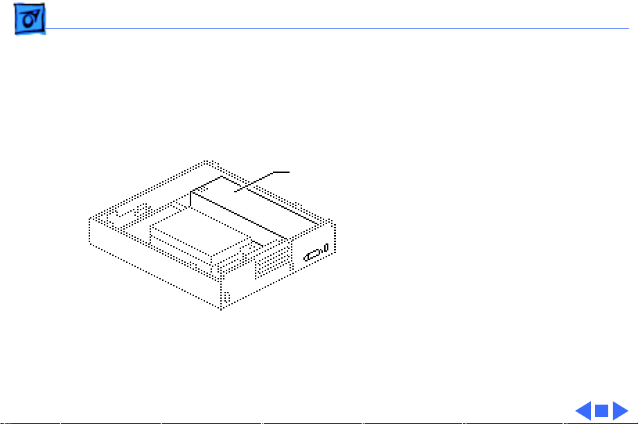
Take Apart Cover - 1
Cover
No preliminary steps are
required before you begin
this procedure.
Cover
Note:
This Take Apart
chapter applies only to the
Apple external hard drive
series (20SC, 40SC, 80SC,
or 160SC). For Take Apart
procedures internal drives,
see the manual for the
computer that contains the
drive.
Page 6
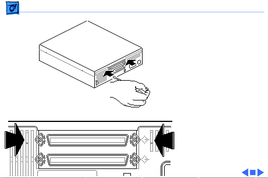
Take Apart Cover - 2
1 Locate the two holding
tabs on the rear of the
hard drive, inside the
ventilation slots.
2 Using a jeweler’s
screwdriver, press in
gently on the two
holding tabs as you push
the cover up slightly.
Page 7
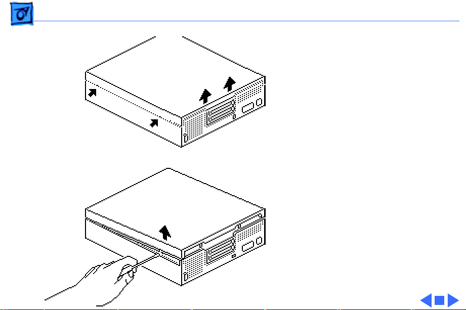
Take Apart Cover - 3
3 Locate the four tab holes,
two on each side of the
hard drive.
4 Starting with the rear
holes, insert the
jeweler’s screwdriver
straight into each of the
holes. Nudge the cover
upward as you release
each tab.
Note:
Prying is not
necessary and may damage
the case.
Page 8
Take Apart Power Supply - 4
Power Supply
Before you begin, remove
the cover.
Power Supply
Caution:
precautions in Bulletins/
Safety.
Review the ESD
Page 9

Take Apart Power Supply - 5
1 Press down on the back
of the power supply,
push back the power
supply tab, and lift the
power supply.
Page 10
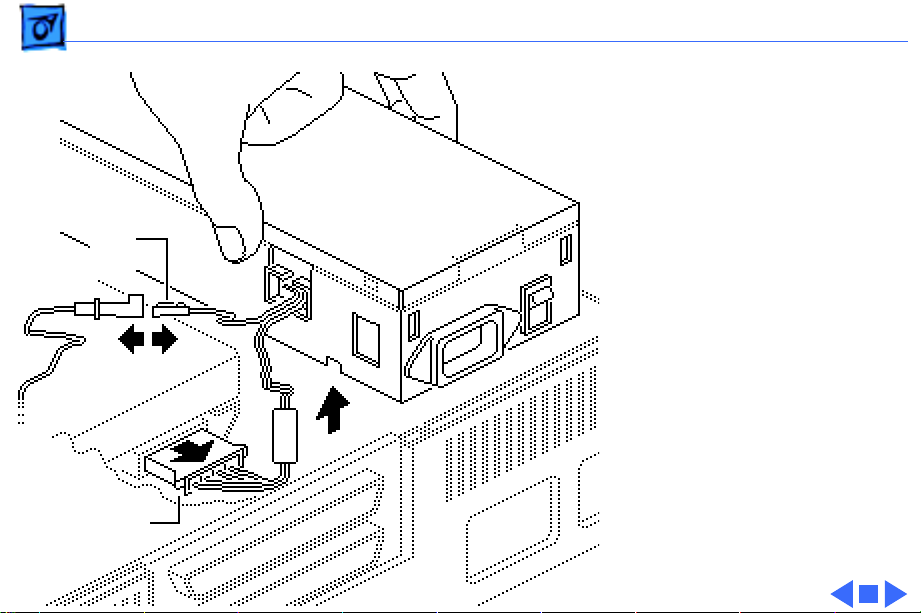
Take Apart Power Supply - 6
2 Disconnect the power
supply connector from
the hard drive
mechanism.
Power Supply
Note:
On some hard
Fan
Cable
drive mechanisms, the
power supply connector
is on the opposite side of
the hard drive.
3 Disconnect the fan cable.
4 Lift the power supply
free.
Power Supply
Connector
Page 11
Take Apart Hard Drive Mechanism - 7
Hard Drive Mechanism
Before you begin, remove
the cover.
Hard Drive
Mechanism
Caution:
precautions in Bulletins/
Safety.
Review the ESD
Page 12
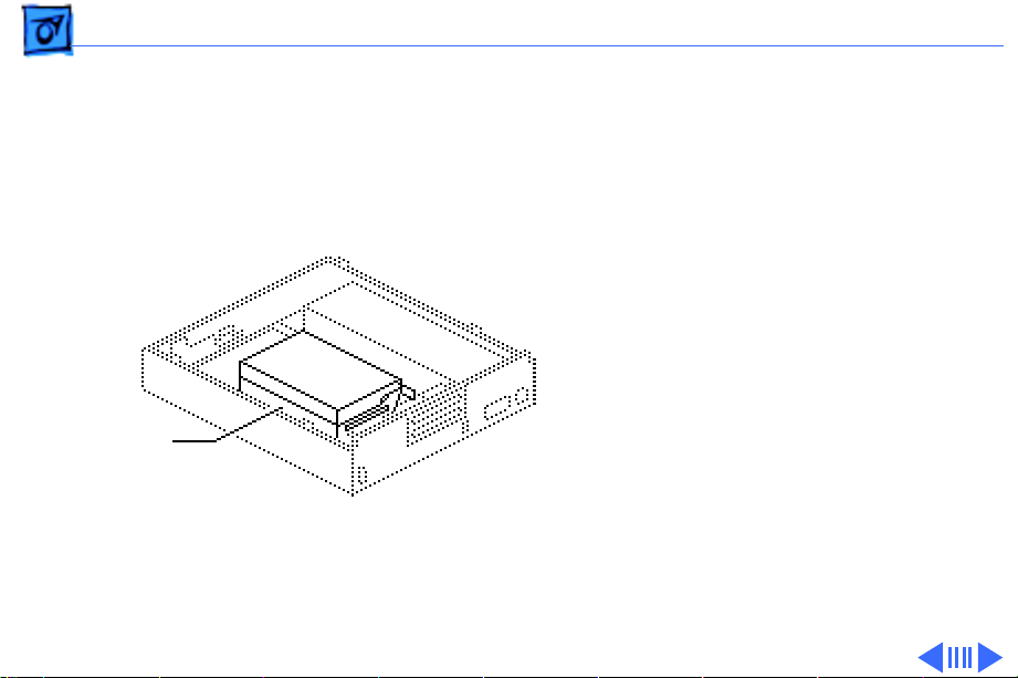
Take Apart Hard Drive Mechanism - 8
1 Push back the large tab,
slide the hard drive
mechanism up, and rest
it on the edge of the case.
Tab
Hard Drive
Mechanism
Page 13

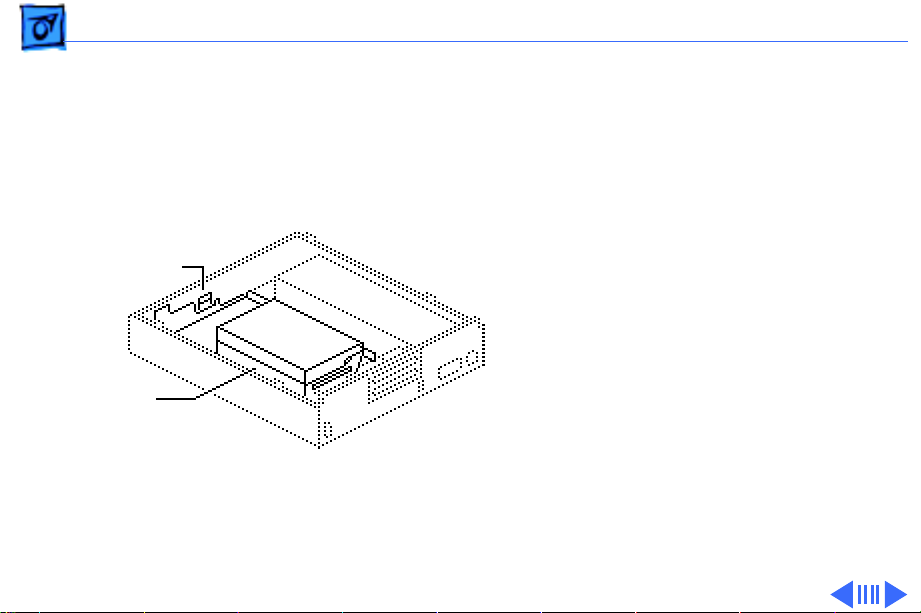
Take Apart Hard Drive Mechanism - 9
2 Disconnect the power
supply.
Note:
SCSI Select
Switch Connector
On some hard
drive mechanisms, the
power supply connector
is located on the
opposite side of the hard
drive.
3 Open the end tabs (if
present) on the hard
drive data cable
connector and disconnect
Power
Supply
Connector
HDA-to-Case
Cable
Hard Drive Mechanism
the cable from the hard
drive mechanism.
Page 14

Take Apart Hard Drive Mechanism - 10
4 Disconnect the SCSI
select switch connector
and lift the hard drive
mechanism out of the
case.
Note:
Skip the following
steps if you are replacing a
20 MB or a 160 MB
external hard drive. Return
these drives to Apple in
their original carriers.
Page 15
Take Apart Hard Drive Mechanism - 11
Note:
Four screws hold the
5.25-inch hard drive along
the bottom edge of the
LED Cable
SCSI Select
Switch
carrier.
5 Turn the drive over and
remove the four screws
near the center of the
metal carrier. Use this
carrier to install the
service replacement
module.
6 Disconnect the LED
cable and SCSI select
switch from the hard
drive mechanism.
Edge of 3.5 Drive
Page 16

Take Apart Hard Drive Mechanism - 12
Note:
Review “Carrier
Removal,” “Modifying 5.25
Drives,” or “Modifying 3.5
Drives” in Additional
Procedures before you
install the new service
replacement drive.
Page 17

Take Apart SCSI Select Switch Cable - 13
SCSI Select Switch Cable
Before you begin, remove
the following:
SCSI Select
Switch
• Cover
• Hard drive mechanism
Caution:
precautions in Bulletins/
Safety.
Review the ESD
Page 18

Take Apart SCSI Select Switch Cable - 14
Slide the cable out of the
holding clamps attached to
the carrier.
Holding Clamps
Page 19

Take Apart LED Cable Assembly - 15
LED Cable Assembly
Before you begin, remove
LED Cable Assembly
the following:
• Cover
• Hard drive mechanism
Caution:
precautions in Bulletins/
Safety.
1 If you are repairing a
Review the ESD
hard drive160SC,
remove the four screws
and pull the end bracket
and the LED cable from
the hard drive.
Page 20

Take Apart LED Cable Assembly - 16
2 Using a jeweler’s
screwdriver, pry the
Retaining Ring
small plastic retaining
ring from around the
LED holder. Slide the
ring up the wires and out
of the way.
3 Press the face of the LED
toward the inside of the
metal carrier until the
LED snaps free of the
plastic holder.
4 Remove the LED cable
assembly.
Page 21

Take Apart Fan Frame - 17
Fan Frame
Before you begin, remove
the cover.
Fan Frame
Caution:
precautions in Bulletins/
Safety.
Note:
disconnect the power supply
when you remove the hard
drive mechanism for this
procedure.
Review the ESD
It is not necessary to
Page 22

Take Apart Fan Frame - 18
Using a flat-blade
screwdriver, push back the
plastic tab and lift out the
metal fan frame (with fan,
HDA-to-case cable, fan
cable, and SCSI select switch
attached).
Plastic Tab
Page 23

Take Apart HDA-to-Case Cable - 19
HDA-to-Case Cable
Before you begin, remove
HDA-to-Case
Cable
the following:
• Cover
• Fan frame
Caution:
precautions in Bulletins/
Safety.
Review the ESD
Page 24

Take Apart HDA-to-Case Cable - 20
1 Remove the four screws
that hold the HDA-tocase cable to the frame.
2 Lift the cable free.
Fan Frame
Page 25

Take Apart Fan - 21
Fan
Before you begin, remove
the following:
• Cover
• Fan frame
• HDA-to-case cable
Fan
Caution:
precautions in Bulletins/
Safety.
Review the ESD
Page 26

Take Apart Fan - 22
1 Remove the two screws
that hold the fan to the
frame.
2 Lift the fan free.
Fan Frame
Page 27

Take Apart SCSI Select Switch - 23
SCSI Select Switch
Before you begin, remove
the following:
SCSI Select
Switch
• Cover
• Fan frame
Caution:
precautions in Bulletins/
Safety.
Review the ESD
Page 28

Take Apart SCSI Select Switch - 24
Push the switch through the
fan frame. Depress the two
plastic tabs—first on one
side and then the other.
Fan Frame
Page 29

K
Service Source
Additional Procedures
External Hard Drive SC
Page 30

Additional Procedures Carrier Removal - 1
Carrier Removal
No preliminary steps are
required before you begin
this procedure.
Note:
This procedure
applies to hard drive
mechanisms that have been
removed from a computer or
an external hard drive, or to
replacement drive
mechanisms that have not
yet been installed in the
computer.
Page 31

Additional Procedures Carrier Removal - 2
Drive
Carrier
Hard
Drive
Caution:
Review the ESD
precautions in Bulletins/
Safety.
Remove the four screws and
lift the carrier from the
hard drive.
Replacement Caution:
Be
sure to properly torque the
replacement drive to its
carrier. Failure to do so
could damage the drive. See
“Torque Sequence” in this
chapter.
Page 32

Additional Procedures Carrier Removal - 3
Note:
For return
information on defective
drives, see “General Return
Info” in this chapter and
refer to the Service Source
parts database Note of the
drive you are returning.
Page 33

Additional Procedures Torque Sequence - 4
Torque Sequence
No preliminary steps are
required before you begin
this procedure.
Note:
This procedure
applies to hard drive
mechanisms that have been
removed from a computer or
an external hard drive, or to
replacement drive
mechanisms that have not
yet been installed in the
computer.
Page 34

Additional Procedures Torque Sequence - 5
Using a torque driver,
tighten the screws in the
order shown. Torque the
screws to 8.0-inch pounds.
Torque Driver
Drive Carrier
Note:
The torque sequence is
the same for all types of
drives and carriers.
Hard Drive
Page 35

Additional Procedures Modifying 5.25 Drives - 6
External Hard Drives Only
Modifying 5.25 Drives
No preliminary steps are
required before you begin
this procedure.
Note:
This section describes
procedures for modifying
5.25-inch replacement
hard drives that are
qualified for external hard
drives. To learn whether a
replacement drive is a
qualified external drive,
refer to compatibility
information in the Service
Page 36

Additional Procedures Modifying 5.25 Drives - 7
Source parts database Note
for the drive.
Note:
The 20 MB and160
MB external 5.25-inch
replacement hard drives
Customer’s
External
Carrier
ship prepared for external
drives. You must modify
other replacement hard
drives for use in external
hard drives.
1 Remove the four
mounting screws and
carrier from the 5.25inch service
replacement hard drive.
Power Cable
Page 37

Additional Procedures Modifying 5.25 Drives - 8
2 Disconnect the power
cable (if attached) from
Termination
Resistors
the replacement drive.
3 Disconnect the
termination resistors
from the component side
of the service
replacement drive. Use
needlenose pliers and
SCSI Select Cable
Jumpers
pull the resistors
straight up.
Replacement Note:
Be
sure that the tab on the
SCSI select cable
connector points toward
the hard drive data cable.
Page 38

Additional Procedures Modifying 5.25 Drives - 9
4 Connect the SCSI select
cable to the three pairs
Customer’s
External Carrier
of pins on the component
side of the replacement
drive. Leave the black
jumpers on the other
pins.
5 Connect the LED cable
connector from the
LED
customer’s external
carrier to the component
side of the replacement
drive.
Page 39

Additional Procedures Modifying 5.25 Drives - 10
6 Attach the reconfigured
replacement hard drive
in the customer’s
external carrier with
the four screws.
Note:
For return
information on defective
drives, see “General Return
Info” in this chapter and
refer to the Service Source
parts database Note of the
drive you are returning.
Page 40

Additional Procedures Modifying 3.5 Drives - 11
External Drives Only
Modifying 3.5 Drives
No preliminary steps are
required before you begin
this procedure.
Note:
This section describes
procedures for modifying
3.5-inch replacement hard
drives that are qualified for
external hard drives. To
learn whether a replacement
drive is a qualified external
drive, refer to compatibility
information in the Service
Source parts database Note
for the drive.
Page 41

Additional Procedures Modifying 3.5 Drives - 12
Note:
The External 20MB
SCSI, Rev A replacement
hard drive ships prepared
Power Cable
Termination Resistors
for use in external hard
drives. You must modify
other replacement hard
drives for use in external
hard drives.
1 Remove the 3.5-inch
replacement hard drive
from its carrier.
2 Disconnect the power
cable (if attached) from
the replacement drive.
Note:
The location of the
termination resistors
may differ.
Page 42

Additional Procedures Modifying 3.5 Drives - 13
3 Disconnect the three
termination resistors
from the component side
of the replacement drive.
Use needlenose pliers, if
necessary.
Important:
the customer’s SCSI select
cable to six unkeyed pins on
the controller board. Be
aware that SCSI select cable
connectors differ in both
design and location among
drives.
You must connect
Page 43

Additional Procedures Modifying 3.5 Drives - 14
4 For SCSI select cable
connectors located on
the edge of the drive
Tab
SCSI
Select Cable
controller board:
• Remove any black
jumpers that may be
installed on the
outside pins.
• Face the tab up and
attach the SCSI cable
connector.
Page 44

Additional Procedures Modifying 3.5 Drives - 15
5 For SCSI select cable
SCSI
Select
Cable
Tab
connectors located on
the surface of the
controller board:
• Face the SCSI cable
connector tab toward
the center of the drive.
• Attach the connector
to the six pins closest
to the 50-pin SCSI
connector.
Page 45

Additional Procedures Modifying 3.5 Drives - 16
Important:
SCSI select connectors and
cables vary. To verify the
proper position of the SCSI
select cable connector,
connect the drive to a
known-good Macintosh and
choose Get Info from the
Finder’s File menu. If Get
Info displays the wrong
SCSI ID or drive name,
reverse the tab of the SCSI
select cable connector.
Combinations of
Page 46

Additional Procedures Modifying 3.5 Drives - 17
Customer's
External Carrier
LED
6 Connect the LED cable
connector from the
customer’s external
carrier to the component
side of the replacement
drive.
7 Install the reconfigured
replacement hard drive
in the customer’s
external carrier.
Note:
For return
information on defective
drives, see “General Return
Info” in this chapter and
refer to the Service Source
Parts database Note of the
drive you are returning.
Page 47

Additional Procedures General Return Info - 18
General Return Info
No preliminary steps are
required before you begin
this procedure.
Note:
You must return a
defective hard drive to Apple
with the correct
combination of carrier and
cables.
Page 48

Additional Procedures General Return Info - 19
Return defective hard drives
in one of three carrier
combinations:
• Switch the hard drive
carriers.
• Return the drive without
a carrier.
• Return the drive with the
carrier from the
customer’s unit.
Note:
For specific return
requirements, refer to the
Service Source Parts
database Note of the drive
you are returning.
Page 49

Additional Procedures General Return Info - 20
Each drive has four cables
that may or may not need to
be returned:
LED Cable
SCSI Select Cable
• Power cable
• Hard drive data cable
Hard Drive
Data Cable
• SCSI select switch cable
• LED cable
Note:
For specific return
requirements, refer to the
Service Source parts
database Note of the drive
you are returning.
Power Cable
Page 50

Additional Procedures Setting SCSI ID - 21
Setting SCSI ID
No preliminary steps are
SCSI Select Pins
required before you begin
this procedure.
To set the SCSI ID, locate the
drive’s six SCSI select pins.
Note:
If you are installing
the drive in a docking
station, such as the
DuoDock, Apple
recommends you change the
SCSI ID to 1. If you are
installing the drive
mechanism in an external
drive case, Apple
Page 51

Additional Procedures Setting SCSI ID - 22
recommends you change the
SCSI ID to any number from
2 to 6.
Note:
The location of the
SCSI select pins varies
among drives. Generally, the
group of six (occasionally
eight) pins is on the top or
side of the printed circuit
board.
Place jumpers on the pairs
of pins as shown in the table
below.
Page 52

Additional Procedures Setting SCSI ID - 23
Note:
In the following table, the SCSI ID numbers are
labeled across the top and the pin numbers are labeled on the
side. (The pin pairs may be labeled using either the A0-A1A2 pin number convention or the E1-E2-E3 convention.
Some pin pairs may not be labeled.) The letter “J” indicates
a jumper.
01234567
A0/E1 - J - J - J - J
A0/E2 - - J J - - J J
A0/E3 ----JJJJ
 Loading...