


SMARTUPS 700
w w w
.apc.com
Back-UPS® LS
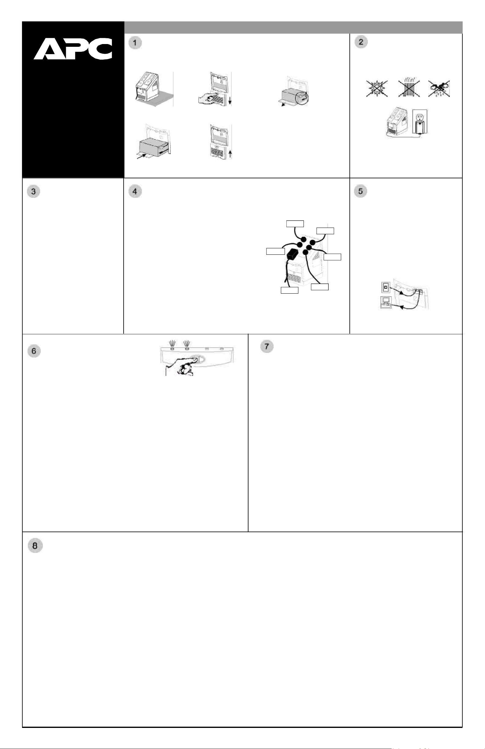
Setup
®
Connect Battery Wire (must be completed FIRST)
The UPS is shipped with one battery wire disconnected, in compliance with Department of Transportation
(DOT) regulations. Connect the battery wire as shown. The UPS will NOT operate unless the steps
below are performed.
Power the UPS
Position the UPS to avoid:
• Direct sunlight
• Excessive heat
• Excessive humidity or contact with liquids.
350/500/700
User’s Manual
990-2052G 8/01
Check Building
Wiring Fault
Indicator
If the Building Wiring Fault indicator on the
power plug stays lit, one of the following
conditions exist:
• Open or high resistance ground
• Hot and neutral polarity reversal
• Overloaded neutral circuit
A lit indicator means that a possible shock
hazard exists. Improper building wiring
should be corrected by a qualified electrician.
Note: Improper building wiring will not prevent
the UPS from operating but will limit its
protection capability. Improper building wiring
could result in equipment damage that is not
covered by APC. Please refer to APC’s
Equipment Protection Policy for details.
a. Set the UPS at the edge
of a table.
d. Slide the battery back in.
Avoid pinching the wires.
b. Slide the battery
compartment cover down.
e. Slide the battery compartment
cover back into place.
Connect Equipment to UPS
DO NOT PLUG SURGE PROTECTORS OR POWER STRIPS INTO BATTERY
BACKUP OUTLETS (EXPLAINED IMMEDIATELY BELOW).
Battery Backup Plus Surge Protection outlets (4)
The four battery backup plus surge protection outlets (along the left in
the graphic) should be used for sensitive equipment such as
computers, monitors, and external drives. Battery power is
automatically provided in case of power outage. When the UPS is
switched Off, neither utility nor battery power is supplied to these
outlets.
Surge Protection outlets (3)
The three surge protection outlets (along the right in the graphic)
should be used for all other peripherals such as a printer, scanner, fax
machine or even an office lamp. These outlets do not provide power
during a power outage. These outlets are always on (when utility
power is available) and are not controlled by the front panel switches.
Transformer Block outlets (2)
One battery backup plus surge protection and one surge protection
outlet accept transformer blocks (bottom outlet on left and right).
c. Grasp the tab attached to the battery
and slide the battery partially out.
Connect the black wire to the battery
by pushing it all the way onto the
terminal. Small sparks at the battery
terminals are normal when
connecting.
Typical Installation
Monitor
Fax
Computer
External
Printer
Scanner
Plug the UPS directly into a wall outlet.
• The Building Wiring Fault indicator in the power
plug may flash momentarily while plugging in.
• The UPS begins charging when connected to
utility power.
• Four hours of charging should be sufficient to
achieve maximum battery capacity.
Connect Phone
Lines to Surge
Protection
The telephone surge protection protects up to two
analog (not digital) phone lines that are serviced
by one phone cable.
One cable connects the wall outlet to the UPS jack
“Wall Outlet”. The other cable connects the UPS
jack “Modem/Fax/Phone” to the equipment
(phone, fax, external modem, computer). If you
need to connect two pieces of equipment, you will
need to use a line splitter.
When plugging the phone lines into the back of
the UPS, the release tab you depress to unplug the
phone line should be facing up.
Switch On and
Test the UPS
Press the On/Test button. The following events then occur:
• The green On Line indicator will flash.
• The red Overload indicator may flash briefly.
• The yellow On Battery indicator will light while a battery test is performed.
• When the self-test has successfully completed, only the green On Line indicator will be lit.
Following the test, if a red indicator is displaying, consult the Troubleshooting section overleaf.
Note: When your UPS goes on battery it produces an audible beep: you can stop the beep without
interfering in normal operation by pressing the On/Test button.
To Perform a Self-Test
You can perform a self-test after the battery is fully charged and while the UPS is On Line by pressing and
holding the On/Test button for more than one second and then releasing it.
Green On Line and Red Overload Indicator
When the green On Line and red Overload indicators are flashing alternately, it means that the UPS has
entered sleep mode and the battery power is switched off. This flashing lasts for 16 seconds after the UPS
has been shut down by the software and is an expected occurrence.
If your computer has been shut down by the software (Power Management Extensions or APC Shutdown
Manager), i.e. the OS shutdown warning message has already displayed, and then AC power is restored
prior to the UPS entering sleep mode, proceed in one of these ways:
Wait at least one minute before manually restarting your computer (to allow the UPS to complete its
shutdown cycle) OR restart your computer by switching the UPS Off then On again and, if necessary,
pressing the power button on your computer.
IMPORTANT: If you manually restart your computer before the UPS has entered sleep mode, your
computer reboot will be interrupted and will shut off as the UPS completes its shutdown cycle.
Connect USB Cable
(optional procedure)
Note that the user’s guide, containing information on using your APC software, is located
in the main folder of your CD-ROM.
Your computer system must be On before starting to connect the USB cable. Connect the
USB cable end, with the USB symbol facing down, to the UPS. Connect the other end of
the USB cable directly to the USB port on your computer.
Attention: USB Extension Cables
USB was designed to operate in the local desktop environment. Though full speed USB
devices can be connected up to 5 meters (16.5 feet) apart, low speed USB devices can only be
connected up to 3 meters (10 feet) apart. The APC Back-UPS LS is a low-speed
peripheral.
The APC Back-UPS LS should be connected directly to the computer with the supplied
USB cable to ensure reliable operation of the software. The standards committee that
created USB does not approve USB extension cables and APC does not recommend them.
Their usage will not harm USB equipment but overall system reliability could be affected.
Install Software (optional procedure, performed after section 7)
For other Microsoft
below, as appropriate:
Windows® 98 and Windows® Me Users
Please insert the APC PowerChute Personal Edition Software CD-ROM included with your
Back-UPS LS into the CD-ROM drive of your computer. The installation program will load
automatically. Please follow the on-screen instructions to install the software.
Windows
The APC PowerChute Personal Edition Software CD-ROM included with your UPS contains a
“wizard” that optimizes your system’s power settings for operation with your Back-UPS LS. It does this
by changing various settings in Power Options Properties in the Control Panel. APC strongly advises
you to reconfigure your system by running this wizard.
1. Insert the APC PowerChute Personal Edition Software CD-ROM into the computer’s CD-ROM
2. Choose “Start” and then the “Run” option. Type: <CD-ROM drive letter>:\setup.exe.
Microsoft
Please visit the APC website at www.apc.com/windowsxp for updates on the availability of
Windows XP software.
®
drive.
Click “OK” and follow the instructions.
®
®
Windows or Macintosh
2000 Users
Windows® XP Users
®
operating systems, please follow the steps
Mac OS 9 (9.0.4/9.1 or higher) Users
APC PowerChute Personal Edition Software has been designed specifically to work with Mac OS 9
(9.0.4/9.1 or higher). There are builds of Mac OS prior to Mac OS 9.0.4/9.1 with power drivers that
have known problems, so please make sure that you have the most up to date version of Mac OS 9
(9.0.4/9.1 or higher).
Insert the APC PowerChute Personal Edition Software CD-ROM into the CD-ROM drive. An icon
called “APC Shutdown Manager v1.0.1” will appear on your desktop. Open the folder and double-click
the “ReadMe” file. Make sure your hardware matches the requirements stated in the ReadMe file.
Double-click on “APC Shutdown Manager v1.0.1” to begin the installation of the software. At the first
dialog, click on “Continue”. Read the displayed license agreement and click “Accept” if you agree to the
terms. Click on “Install” to begin. After installation, click on the “Restart” dialog button to restart your
computer.
All Other Users
The software is designed for the Windows and Macintosh operating systems mentioned in this section. If
you do not have one of these operating systems, your unit will still provide these primary features:
• Battery backup, surge protection, and telephone line protection to protect your entire desktop from
lightning and power surges.
• Runtime needed for you to work through brief power disturbances: this gives you time to manually
save your data and shut down safely.
Installation of the APC PowerChute Personal Edition Software is not mandatory. However, other
features provided by the software include unattended automatic operating system shutdown, as well as
application data saving. To activate these features, install the software as previously discussed.
 Loading...