


APC Silcon
10-40kW 400V UPS
Installation Guide
Copyright 2000 APC Denmark ApS This manual is subject to change without notice and does not represent a commitment on the part of the vendor
Thank You!
Thank you for chosing the APC Silcon Series UPS. Please read this Installation Guide thoroughly prior to installing the system. It provides important information on safe and efficient installation.
The installation and use of this product must comply with national, federal, state, municipal and local codes.
Safety Symbols used in this manual
WARNING! Indicates a hazard which, if not avoided, could result in injury or death.
CAUTION! Indicates a hazard which, if not avoided, could result in damage to the product or other property.
NOTICE! Read and pay attention to this important information.
WARNING!
This UPS unit contains hazardous AC and DC voltages. Only qualified electricians should install the UPS, AC line and external batteries, and must be familiar with batteries and battery installation.
Before installing, maintaining or servicing the UPS, shut off the UPS and disconnect all sources of AC and DC power.
As the UPS has no built-in disconnection devices to switch off external AC and DC input power, ensure that disconnection devices are provided as separate parts in connection with the installation!
The installer must provide each external disconnecting device for this UPS system with labels with the following text:
“Isolate the Uninterruptible Power Supply (UPS) as instructed in this guide before working on circuit”
AC and/or DC voltage will always involve a potential risk of AC voltage at UPS output generated from either batteries or mains. To avoid equipment damage or personal injury, always assume that there may be voltage at UPS output.
This system is equipped with an auto-start function. If activated, the system may start without warning. Refer to the “Programming” section of this guide for information on de-activation.
TEST BEFORE YOU TOUCH!
To reduce the risk of fire or electric shocks, install the UPS and external batteries in a temperature and humidity controlled indoor area, free of conductive contaminants.
UPS batteries are high-current sources. Shorting battery terminals or DC terminals, DC busbars can cause severe arcing, equipment damage and injury. A short circuit can cause a battery to explode. Always wear protective clothing and eye protection and use insulated tools when working on batteries.
CAUTION!
This unit contains components sensitive to electrostatic discharge (ESD). If you do not follow the ESD procedures, you may cause severe damage to electronic components.
990-4050
2 |
Installation Guide APC Silcon 10-40kW 400V UPS |

Contents
1.0 |
Introduction |
5 |
1.1 |
Tools and Equipment |
5 |
2.0 |
Unpacking |
6 |
3.0 |
Installation |
8 |
3.1 |
Requirements on Site |
8 |
3.1.1 |
Cabinet Dimensions H*xWxD - 1400xWx800 [mm]. Width as in below table: |
8 |
3.2 |
Footprint |
10 |
3.2.1 |
600mm UPS Cabinet with 1xBP I or Isolation Transformer |
10 |
3.2.2 |
800mm UPS Cabinet with 1xBP I or Built-in Isolation Transformer, or 2xBP I |
10 |
3.2.3 |
1000mm Cabinet for 10-20kW UPS with 3xBP I |
11 |
3.2.4 |
600mm Cabinet for 40kW UPS without Batteries |
11 |
3.2.5 |
1000mm Cabinet for 40kW UPS with 2xBP I |
12 |
4.0 |
External Connection |
13 |
4.1 |
Connecting the UPS |
13 |
4.1.1 |
Connecting the 10-20kW UPS |
13 |
4.1.2 |
Connecting the 40kW UPS |
15 |
4.2 |
System Integration Interface |
17 |
4.2.1 |
Connections |
18 |
4.3 |
Parallel Board |
19 |
4.4 |
Communication Interface Board |
22 |
4.4.1 |
Connections |
22 |
4.5 |
Connecting of APC Silcon Tripel Chassis |
23 |
4.6 |
APC Silcon Triple Chassis |
24 |
4.6.1 |
Safety Warnings |
24 |
4.6.2 |
Product Description |
24 |
4.6.3 |
Installing Management Peripherals |
25 |
4.6.4 |
Powering the APC Silcon Triple Chassis |
27 |
4.6.5 |
Troubleshooting |
28 |
4.6.6 |
Product Specifications |
29 |
4.7 |
APC Silcon Battery Cabinets |
32 |
4.7.1 |
Cabinets |
33 |
4.7.2 |
Preparing Batteries |
33 |
4.7.3 |
Mounting Batteries |
35 |
4.7.4 |
Final Checks |
37 |
4.7.5 |
APC Silcon Battery Cabinets |
38 |
4.8 |
Battery Breaker Box/Fuse-box |
40 |
4.8.1 |
Battery Breaker Box |
41 |
4.8.2 |
Battery Breaker Box Connection Diagram |
42 |
4.8.3 |
Fuse-box |
43 |
4.8.4 |
Fuse-box Connection Diagram |
44 |
4.8.5 |
UPS with External Battery in Battery Breaker Box/Fuse-box Configuration |
45 |
5.0 |
Programming Parameters |
46 |
5.1 |
Parameters |
46 |
5.1.1 |
Programming Keys |
47 |
5.1.2 |
Programming Example - Switch to Bypass Operation |
48 |
5.2 |
System Configuration |
48 |
5.2.1 |
Programming Example - Change Charge Voltage to 446 |
50 |
5.2.2 |
Programming Example - Change to Output Isolation Transformer available |
51 |
5.3 |
Programming Parameters for Advanced Parallel Operation |
52 |
5.3.1 |
Description of Settings |
52 |
5.3.2 |
Programming example |
53 |
5.4 |
Battery Monitor |
53 |
5.4.1 |
Installation of new batteries |
53 |
6.0 |
Options/Accessories |
54 |
6.1 |
Service Bypass Panel for Single Operation |
54 |
6.1.1 |
Wiring up UPS with SBP in TN-C-S Network |
56 |
6.1.2 |
Wiring up UPS with SBP in TN-S Network |
56 |
|
|
990-4050 |
|
|
|
Installation Guide APC Silcon 10-40kW 400V UPS |
3 |
|

6.1.3 |
Operating The External Service Bypass Switch |
57 |
6.2 |
Service Bypass Panel for Parallel Redundant Operation |
59 |
6.2.1 |
Two Parallel Systems with Service Bypass Panel |
60 |
6.2.2Parallel/Redundant Operation with Service Bypass Panel and External Battery
|
via MCCB |
61 |
6.2.3 |
Operating External Service Bypass Switch for Parallel Systems |
62 |
6.2.4 |
Isolating One UPS for Service/Maintenance |
66 |
6.2.5 |
Switching Back to Normal Parallel/Redundant Operation |
67 |
6.3 |
Intersystem Synchronization Unit |
68 |
6.4 |
Relay Board |
69 |
6.4.1 |
Relay Board/Relay Functions |
70 |
6.5 |
Weight Equalizer |
72 |
6.6 |
Remote Display |
74 |
6.6.1 |
Extension of Remote Display Communication Distance |
74 |
6.6.2 |
Remote Display Installation |
76 |
6.6.3 |
Remote Display Use |
77 |
6.7 |
Isolation Transformer |
78 |
6.7.1 |
Connecting Isolation Transformer |
79 |
6.7.2 |
Wiring up UPS with External Yyn0 Isolation Transformer at Output |
81 |
6.7.3 |
Wiring up UPS with External Yyn0 Isolation Transformer at Input |
82 |
6.7.4 |
Wiring up UPS with External Optional Dzn0 Isolation Transformer at Input |
83 |
6.7.5 |
Wiring up UPS with External Optional Dzn0 Isolation Transformer at Output |
84 |
6.7.6 |
Wiring up UPS with External Optional Dyn11 Isolation Transformer at Input |
85 |
7.0 |
System Specifications |
86 |
7.1 |
Technical Data |
86 |
7.2 |
Back-up Time / Dimensions / Weigh |
86 |
8.0 |
Warranty |
87 |
8.1 |
APC Silcon Series Limited Factory Warranty |
87 |
9.0 |
Appendix |
88 |
9.1 |
Table 1. Installation Planning Data |
88 |
10.0 |
How to Contact APC |
90 |
990-4050
4 Installation Guide APC Silcon 10-40kW 400V UPS

Introduction
1.0 Introduction
Power regulation varies from country to country, and information given in this installation guide can therefore only be of a general nature. Electricians should therefore always refer to national and local electrical codes prior to installing the UPS system.
1.1Tools and Equipment
CAUTION!
Heavy equipment. To prevent personal injury or equipment damage, take extreme care when handling and transporting UPS cabinet and equipment.
CAUTION!
Ensure that front doors are in place and that internal front cover is fastened by screws before attempting to lift or transport the system.
This section lists all tools and equipment required to install all UPS configurations. See also section 4.0 of this guide for further details on connection.
Tools:
•10mm socket
•13mm socket-deep
•17mm socket
•19mm socket-deep
•19mm combo wrench
•Small flat head/regular screwdriver
•#3 philips screwdriver
•Compression lug crimping tool
•Knock-out set (for glands)
Equipment:
•Compression lugs for cable terminations
•Cable to Service Bypass Panel from system feeder
•Cable to UPS input from Service Bypass Panel
•Cable to Service Bypass Panel from UPS output
•Cable from Service Bypass Panel to customer distribution
•Cable to UPS input from external batteries/external Battery Breaker Box (systems with external battery)
•Solid core, control cable to UPS from Service Bypass Panel
•Solid core, control cable to UPS from external batteries/external Battery Breaker Box
|
990-4050 |
|
|
Installation Guide APC Silcon 10-40kW 400V UPS |
5 |
Unpacking
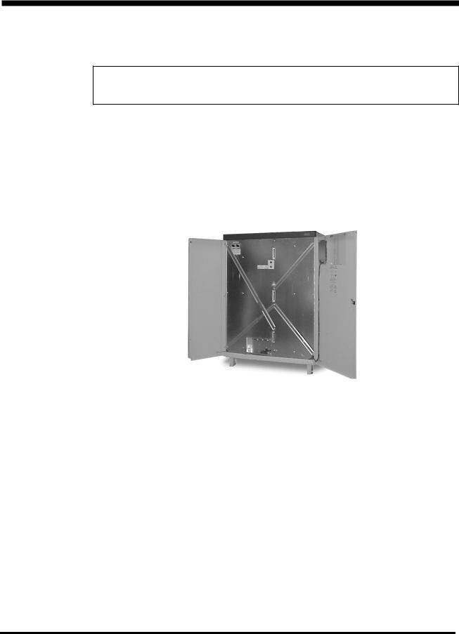
2.0 Unpacking
NOTICE!
Unless otherwise specified by the shipping company use a fork lift to unload equipment from pallet
1.To unpack UPS unit, remove top and bottom screws from side plates of packaging and lift up side plates
2.Verify compliance between type label on reverse side of front door and system ordered. Check input and output voltage
3.Copy type label data to label copy below for easy identification of system
4.Use fork lift to transport system to installation site
5.Open UPS doors and unscrew metal straps mounted on front cover of UPS
990-4050
6 Installation Guide APC Silcon 10-40kW 400V UPS

Unpacking
Copy of type label
PLEASE RECYCLE
The shipping materials for the APC Silcon UPS are recyclable. Please save them for later use or dispose of them appropriately.
|
990-4050 |
|
|
Installation Guide APC Silcon 10-40kW 400V UPS |
7 |

Installation
3.0Installation
3.1Requirements on Site
All system parts are accessible from front or top of UPS. Cable entries are accessible from bottom. A 1m free space on all sides should be allowed during installation. Once the system is installed it may be placed close to walls as long as free space is allowed for system doors to open. (Per applicable national and/or local codes.)
For ventilation and service purposes allow for free space of minimum 1m above the unit or per national and/or local codes and in front of UPS. Never install systems in direct sunlight.
NOTICE!
For reliability reasons do not stand on the UPS. keep the UPS cabinet surface free of any objects.
3.1.1 Cabinet Dimensions H*xWxD - 1400xWx800 [mm]. Width as in below table:
* H is 1500 mm for optional IP31 cabinets
|
Width |
Width With Built-in Batteries |
Width for Separate |
|||
|
Without |
|
[mm] |
|
Battery Cabinets |
|
|
Batteries |
|
|
|
[mm] |
|
|
[mm] |
|
|
|
|
|
|
|
|
|
|
|
|
UPS |
|
1xBP I* |
2xBP I* |
3xBP I* |
1xBP II** |
1xBP III*** |
|
|
|
|
|
|
|
10kW |
600 |
600 |
800 |
1000 |
1x800 |
1x1000 |
|
|
|
|
|
|
|
20kW |
600 |
600 |
800 |
1000 |
1x800 |
1x1000 |
|
|
|
|
|
|
|
40kW |
600 |
|
1000 |
|
1x800 |
1x1000 |
|
|
|
|
|
|
|
*BP I = Battery Pack I = 1 x 64 x 7 Ah batteries
**BP II = Battery Pack II = 1 x 64 x 24Ah batteries
***BP III = Battery Pack III = 1 x 64 x 38 Ah batteries
990-4050
8 Installation Guide APC Silcon 10-40kW 400V UPS

Installation
Cabinets |
|
|
|
|
|
|
|
|
|
|
|
|
|
|
|
|
|
|
|
|
|
|
|
|
|||||
|
|
600 mm wide |
|
|
|
800 mm wide |
|
|
|
1000 mm wide |
|||||||||||||||||||
1400 mm |
|
|
|
|
|
1400 mm |
|
|
|
|
|
|
|
|
|
|
|
|
1400 mm |
|
|
|
|
|
|
|
|
|
|
|
|
|
|
|
|
|
|
|
|
|
|
|
|
|
|
|
|
|
|
|
|
|
|
|
|
|
|||
|
|
|
|
|
|
|
|
|
|
|
|
|
|
|
|
|
|
|
|
|
|
|
|
|
|
|
|
|
|
|
|
10-20kW |
|
|
|
|
|
|
|
10-20kW |
|
|
|
|
|
10-20kW |
|
||||||||||||
|
|
with 1xBP l |
|
|
|
|
with 2xBP l |
|
|
|
|
with 3xBP l |
|||||||||||||||||
600 mm wide |
|
|
|
|
1000 mm wide |
|
|
|
|
|
|
|
|
|
|
|
|||||||||||||
|
|
|
|
|
|
|
|
|
|
|
|
|
|
|
|
|
|
|
|
|
|
|
|
||||||
1400 mm |
|
|
|
|
|
1400 mm |
|
|
|
|
|
|
|
|
|
|
|
|
|
|
|
|
|
|
|||||
|
|
|
|
|
|
|
|
|
|
|
|
|
|
|
|
|
|
|
|
|
|
|
|
|
|
||||
|
|
|
|
|
|
|
|
|
|
|
|
|
|
|
|
|
|
|
|
|
|
|
|
|
|
||||
|
|
40kW |
|
|
|
|
|
40kW with 2xBP l |
|
|
|
|
|
|
|
|
|
|
|
||||||||||
without batteries |
|
|
|
|
|
|
|
|
|
|
|
|
|
|
|
|
|
|
|
|
|
|
|
|
|||||
600 mm wide |
|
|
|
|
|
|
800 mm wide |
|
|
|
|
1000 mm wide |
|||||||||||||||||
1400 mm |
|
|
|
|
|
1400 mm |
|
|
|
|
|
|
|
|
|
|
|
|
1400 mm |
|
|
|
|||||||
|
|
|
|
|
|
|
|
|
|
|
|
|
|
|
|
|
|
||||||||||||
|
|
|
|
|
|
|
|
|
|
|
|
|
|
|
|
|
|
|
|
|
|
||||||||
APC Isolation |
|
|
|
|
|
|
Battery cabinet |
|
|
|
|
Battery cabinet |
|||||||||||||||||
Transformer module |
|
|
|
|
|
|
for 1xBP ll |
|
|
|
|
for 1xBP lll |
|||||||||||||||||
|
|
10-80kW |
|
|
|
|
|
|
|
|
|
|
|
|
|
|
|
|
|
|
|
|
|
|
|
|
|||
|
990-4050 |
|
|
Installation Guide APC Silcon 10-40kW 400V UPS |
9 |

Installation
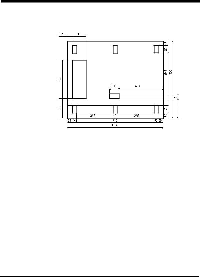
3.2Footprint
3.2.1 600mm UPS Cabinet with 1xBP I or Isolation Transformer
Rear
Power entrycable
Com. cable entry
Front
3.2.2 800mm UPS Cabinet with 1xBP I or Built-in Isolation Transformer, or 2xBP I
Rear
entrycable
Power Com. cable
entry
Front
990-4050
10 |
Installation Guide APC Silcon 10-40kW 400V UPS |
Installation
3.2.3 1000mm Cabinet for 10-20kW UPS with 3xBP I
Rear
Power cable entry
Com. cable entry
Front
3.2.4 600mm Cabinet for 40kW UPS without Batteries
Rear
Power entrycable
Com. cable entry
Front
|
990-4050 |
|
|
Installation Guide APC Silcon 10-40kW 400V UPS |
11 |
Installation
3.2.5 1000mm Cabinet for 40kW UPS with 2xBP I
Rear
Power cable entry
Com. cable entry
Front
195 0
990-4050
12 Installation Guide APC Silcon 10-40kW 400V UPS
External Connection
4.0External Connection
4.1Connecting the UPS
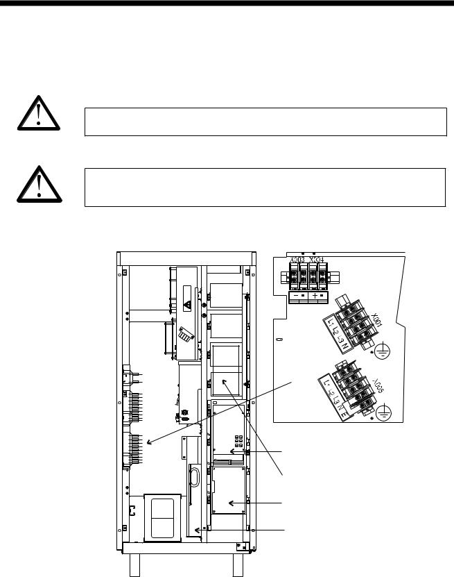
4.1.1Connecting the 10-20kW UPS
CAUTION!
At a switch mode load of 100% the neutral must be rated for 200% output phase current
CAUTION!
This UPS unit is an EN 50091-2 product and may cause radio interference in a domestic environment. Take preventive measures if necessary.
Optional
Input
Ext. batteries optional
Output
System Integration Interface
Relay Board (Optional)
Communication Interface
Parallel Controller Board
|
990-4050 |
|
|
Installation Guide APC Silcon 10-40kW 400V UPS |
13 |

External Connection
NOTICE!
Check correct phase rotation of mains input voltage!!
Max. input/output cables: 35mm2.
If there is no neutral input Dzn0 or Dyn11 input isolation transformer is required.
UPS |
External |
External |
External PE |
Maximum |
External |
|
Input Fuses* |
Input Cable |
Cable [mm2] |
External |
OutputCable |
|
FM [A] |
[mm2] |
|
Output |
[mm2] |
|
380-415V |
380-415V |
|
Fuses* |
|
|
|
|
|
[A] |
|
|
|
|
|
|
|
10kW |
20 |
4 |
4 |
16 |
2.5 |
|
|
|
|
|
|
20kW |
40 |
10 |
10 |
32 |
6 |
|
|
|
|
|
|
*DIN gL types
NOTICE!
All cable dimensions are recommended sizes only. Refer to local legal regulations.
UPS |
External Alarm |
External System |
External Battery |
External |
|
Cable max. |
Earth Cable |
Breaker |
Battery Cable |
|
[mm2] |
[mm2]** |
[A] |
[mm2] |
|
|
|
|
|
10kW |
2 |
4 |
25 |
4 |
|
|
|
|
|
20kW |
2 |
4 |
50 |
10 |
|
|
|
|
|
PVC cables isolated to withstand ambient temperature of max. 30oC
** Must be rated as external PE cable if mains system is not supplying PE
NOTICE!
If an MCCB is used instead of external input fuses, the MCCB load capacity must be 8xIn (nominal current) for min. 10ms.
990-4050
14 Installation Guide APC Silcon 10-40kW 400V UPS
External Connection
NOTICE!
Install gland plate in bottom of unit
4.1.2 Connecting the 40kW UPS
CAUTION!
At a switch mode load of 100% the neutral must be rated for 200% output phase current.
CAUTION!
This UPS unit is an EN 50091-2 product and may cause radio interference in a domestic environment. Take preventive measures if necessary.
Optional |
Input |
Output |
Parallel Controller |
Please refer to 8.5 |
System Integration interface |
Communication Interface |
Relay Board (Optional) |
|
990-4050 |
|
|
Installation Guide APC Silcon 10-40kW 400V UPS |
15 |

External Connection
NOTICE!
Check correct phase rotation of mains input voltage!!
Max. input/output cables: 120mm2. Battery: 70 mm2.
If there is no neutral input Dzn0 or Dyn11 input isolation transformer is required.
UPS |
External |
External |
External PE |
Maximum |
External |
|
Input |
Input Cable |
Cable |
External |
Output |
|
Fuses* FM |
[mm2] |
[mm2] |
Output |
Cable |
|
[A] |
380-415V |
|
Fuses* |
[mm2] |
|
380-415V |
|
|
[A] |
|
|
|
|
|
|
|
40kW |
80 |
25 |
16 |
63 |
16 |
|
|
|
|
|
|
*DIN gL types
NOTICE!
All cable dimensions are recommended sizes only. Refer to local legal regulations.
UPS |
External Alarm |
External System |
External Battery |
External |
|
Cable max. |
Earth Cable |
Breaker |
Battery Cable |
|
[mm2] |
[mm2]** |
[A] |
[mm2] |
|
|
|
|
|
40KW |
2 |
10 |
63 |
16 |
|
|
|
|
|
PVC cables isolated to withstand ambient temperature of max. 30oC.
** Must be rated as external PE cable if mains system is not supplying PE.
NOTICE!
Install gland plate in bottom of unit.
990-4050
16 Installation Guide APC Silcon 10-40kW 400V UPS
External Connection
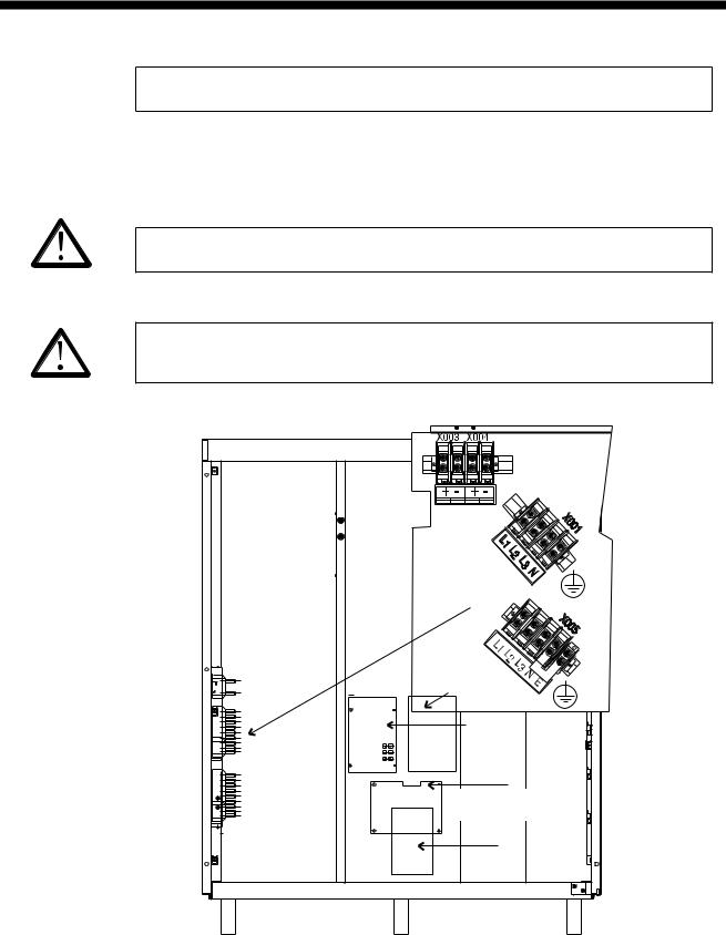
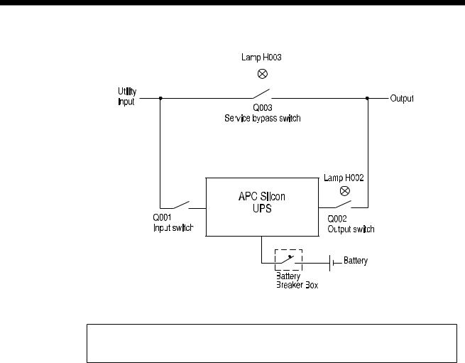
4.2System Integration Interface
NOTICE!
Consistent use of designations (Q001, Q002, Q003, H002, H003) in diagrams simplifies information exchange.
System Integration Interface (SII) is the control link between UPS and system main switches as shown in above diagram. The purpose of the SII is to ensure correct operation of switches without losing system output power.
Auxiliary contacts on the main switches transmit the SII board inputs. Lamps on Service Bypass Panel and Battery Breaker Box/Battery Cabinet indicate “green light” for operation of output switches.
SII board also integrates input facilities for emergency shut-down and temperature compensation of charge voltage for external battery (use with battery monitor). “Battery operation” and “Common fault” are two main SII board status relay signals.
|
990-4050 |
|
|
Installation Guide APC Silcon 10-40kW 400V UPS |
17 |
External Connection
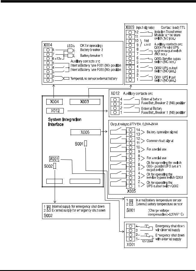
4.2.1 Connections
Blue |
Brown |
990-4050
18 Installation Guide APC Silcon 10-40kW 400V UPS
External Connection
Terminal Blocks: X003/X004 (Anxiliary Contacts)
When switching Q001, Q002, Q010, Battery Breaker 1 or Battery Breaker 2 from “ON or 1” to “OFF or 0”, the anxiliary contact has to be open BEFORE the corresponding main contacts are opened. When switching Q001, Q002, Q010, Battery Breaker 1 or Battery Breaker 2 the opposite way from “OFF or 0” to “ON or 1”, the anxiliary contact has to close with a maximum delay of 0.5 seconds from the time the corresponding main contacts are closed.
•This type of auxillary contact is called a “late make” contact. (This also means that it will “break early” when activated in opposite direction.)
•This auxillary contact is also called “NORMALLY OPEN” (NO), because the auxillary contact will be open when the main contacts are open.
•Please note that the above term “NORMALLY” has nothing to do with NORMAL UPS OPERATION MODE.
When switching Q003 from “OFF or 0” to “ON or 1”, the anxiliary contact has to open BEFORE the corresponding main contacts are closed. When switching Q003 the opposite way from “ON or 1” to “OFF or 0”, the auxillary contact has to close with a maximum delay of 0.5 seconds from the time when the corresponding main contacts are opened.
•This type of anxiliary contact is called an “early break” contact. (This also means that it will “make late” when activated in the opposite direction.)
•The auxiliary contact is also called “NORMALLY CLOSED” (NC), because the auxiliary contact will be closed when the main contacts are open.
•Please note that the above term “NORMALLY” has nothing to do with NORMAL UPS OPERATION.
X005 (Output Relays)
Battery operation signals are received with a 30-second delay. This function is inactive during battery test. Common fault relay facility is programmable (standard factory setting: 10 sec.) See APC Silcon User Guide for details.
Maximum nominal voltage on contact circuits is 277VAC. If two different phases are involved, maximum phase to neutral voltage should be below 160VAC. Please note that phase L1 is already present on the System Integration Interface board, supplied from the Service Bypass Panel. Therefore, if a phase is needed for alarm or signal purposes, Phase L1 should be used.
4.3Parallel Board
CAUTION!
Control cables must be separated from AC and DC power cables.
Parallel Board
|
990-4050 |
|
|
Installation Guide APC Silcon 10-40kW 400V UPS |
19 |
External Connection
The built-in parallel board connects two or more UPS systems in parallel, either to obtain increased system reliability or to obtain higher output power. The parallel board also ensures correct load-sharing between paralled systems.
NOTICE!
For reliability reasons, APC recommends separate battery packs in redundant/parallel conigurations.
To prepare the UPS for parallel/redundant mode, disconnect all sources of AC and DC power supply to the UPS and connect the ribbon cable from the parallel board to the main controller board (the ribbon cable is delivered with the UPS).
CAUTION!
DO NOT connect ribbon cable between controller and parallel card in single configurations.
Ribbon cable is for parallel operation only.
Complete the parallel system set-up by connecting the external control cables (see below). Follow the instructions in the “Programming Parameters for Advanced Parallel” section of this guide to execute necessary re-programming.
990-4050
20 Installation Guide APC Silcon 10-40kW 400V UPS
External Connection
Parallel Board
X021:15-pin SUB-D female
X020:15-pin SUB-D female
External multicore cable with 14 wires + shield to other parallel units
UPS 1 |
|
|
|
UPS 2 |
|
UPS 3 |
|
|||||||||
|
|
|
|
|
|
|
|
|
|
|
|
|
|
|
|
|
|
|
|
|
|
|
|
|
|
|
|
|
|
|
|
|
|
|
|
|
|
|
|
|
|
|
|
|
|
|
|
|
|
|
|
|
|
|
|
|
|
|
|
|
|
|
|
|
|
|
|
|
|
|
|
|
|
|
|
|
|
|
|
|
|
|
|
|
|
|
|
|
|
|
|
|
|
|
|
|
|
|
|
|
|
|
|
|
|
|
|
|
|
|
|
|
|
|
|
|
|
|
|
|
|
|
|
|
|
|
|
|
|
|
|
|
|
|
|
|
|
|
|
|
|
|
|
|
|
|
|
|
|
|
|
|
External Control Cables
External multicore cable is equipped with 15-pin SUB-D plug at either end. Connect pin 1 to pin 1, and pin 2 to pin 2 etc. up to pin 15 - with the exception of pin 8, which is not to be connected.
Shield is connected to plug cover at both ends.
Terminals X020 and X021 for control cables located on parallel board. Connect X020 in UPS1 to X021 in UPS2, and connect X020 in UPS2 to X021 in UPS3 etc. Connect X020 in last UPS to X021 in UPS1.
Cable is delivered with the UPS.
Power Cables
To optimize load-sharing in parallel operation, external power circuits must be “symmetrical”: Power input and output cables to have same length and identical cross-sections.
|
990-4050 |
|
|
Installation Guide APC Silcon 10-40kW 400V UPS |
21 |
External Connection
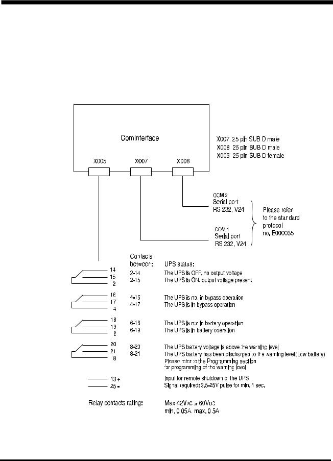
4.4Communication Interface Board
The 3-port ComInterface is used to establish an interaction between UPS and e.g. a computer system. Main purpose: To ensure a controlled computer shut-down in case of a mains supply failure.
4.4.1 Connections
. .
990-4050
22 Installation Guide APC Silcon 10-40kW 400V UPS
External Connection
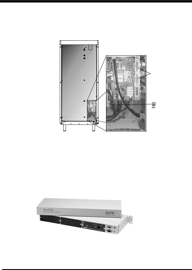
4.5Connecting of APC Silcon Tripel Chassis
The enclosed Triple Chassis must be connected to the serial port on the Communication Interface Board, and to the 24V supply (cables included). Terminal locations shown below.
23.62 inch/600mm Cabinet
Serial ports
Front view of UPS Cabinet (doors open) |
X50 is a 24V supply for Triple Chassis. |
|
|
|
Only to be used for this purpose. |
|
Not suitable for telephone equipment. |
|
Triple Chassis must be connected to both |
|
X50 and a serial port. |
APC Silcon Triple Chassis
For more information please refer to the following section.
990-4050
Installation Guide APC Silcon 10-40kW 400V UPS |
23 |
External Connection
4.6APC Silcon Triple Chassis
The APC Silcon Triple Chassis (AP9604S) is an American Power Conversion (APC) external management peripheral that allows you to use monitoring and control management peripherals with your APC Silcon series UPS. The retrofit model (AP9604SR) is for use with Silcon series UPSs that are not equipped with a 24 VDC power port.
4.6.1 Safety Warnings
Use the APC Silcon Triple Chassis only in conjunction with an APC Silcon UPS.
Do not connect a computer to any APC Silcon Triple Chassis port using a straight-through extension cable. Use the communications cable provided with the APC Silcon Triple Chassis.
Connections using a cable made by any other manufacturer may cause damage or improper operation of the APC Silcon Triple Chassis, the UPS, or the computer.
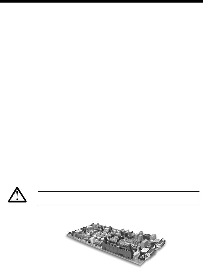
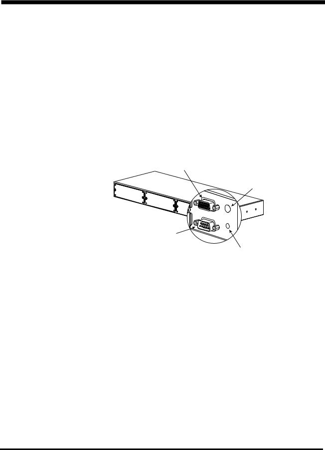
4.6.2 Product Description
1 |
Monitoring port |
3 |
Status LED |
2 |
To UPS port |
4 |
Optional Power port |
4.6.2.1Monitoring Port
The Monitoring port has two functions:
•Connecting to a terminal for configuration of the chassis. For direct connection to the Monitoring port, you must use the Monitoring cable supplied with the chassis (APC P/N 940-0024C).
•Connecting to other APC external management peripherals in a daisy chain.
4.6.2.2To UPS Port
The “To UPS” port connects the chassis to the UPS, using the Silcon UPS cable (APC P/N 9400071). The cable connector plugs into a communications port on an APC Silcon UPS.
990-4050
24 |
Installation Guide APC Silcon 10-40kW 400V UPS |

External Connection
4.6.2.3LEDs
The APC Silcon Triple Chassis status LED provides important information concerning operation of the chassis. Refer to the table below for a description of the conditions indicated by the LED.
IF the LED is… |
THEN the Silcon Triple Chassis… |
|
|
|
|
off |
is not receiving power. |
|
|
|
|
|
has not been configured. See the APC Silcon Management Quick |
|
flashing quickly |
Start Guide provided with your chassis or the Web/SNMP |
|
(5 times per second) |
Management Card Installation Guide on the CD for more |
|
|
information. |
|
|
|
|
flashing slowly |
is powered on but is not communicating with the UPS. |
|
(1 time per second) |
||
|
||
|
|
|
on |
is operating normally. |
|
|
|
4.6.2.4Optional Power Input
With the Optional Power input, you can power the APC Silcon Triple Chassis from an external source, using a 24 VDC power adapter. A universal adapter (AP9505i) or a standard adapter (AP9505) can be purchased separately from APC.
4.6.3 Installing Management Peripherals
There are two basic types of APC management peripherals that work with the APC Silcon Triple Chassis:
•Management peripheral cards, which fit into external management peripherals that are equipped with a card slot.
•External management peripherals, which connect to the Monitoring (or Advanced) port of other external management peripherals.
NOTICE!
The name “Monitoring” port varies from product to product, but its purpose is the same – to replicate the UPS communications port.
990-4050
Installation Guide APC Silcon 10-40kW 400V UPS |
25 |

External Connection
4.6.3.1Order of Management Peripheral Cards
Because UPS signals are passed between management peripherals, you must install management peripheral cards in the correct order for them to work together properly. The card slots are numbered 1 to 3, from left to right, as viewed from the rear of the chassis. The following table lists the management peripheral cards, their priority, and proper position.
Management |
P/N |
Priority |
Position |
||
Peripheral Card |
|||||
|
|
|
|
||
|
|
|
|
|
|
Web/SNMPManagement |
AP9606 |
Highest |
High-numbered slot |
||
Card |
|
|
|||
|
|
|
|
||
|
|
|
|
|
|
Out-of-Band |
|
|
|
|
|
|
|
|
|
||
Management Card |
AP9608 |
Second-highest |
|
|
|
(Call-UPS®II) |
|
|
|
|
|
Interface Expander |
AP9607 |
Second lowest |
|
|
|
|
|
|
|
|
|
Environmental |
AP9612T |
|
|
|
|
Monitoring Card |
Lowest |
|
|
||
AP9612TH |
|
|
|||
(Measure-UPS® II) |
|
Low-numbered slot |
|||
|
|
||||
4.6.3.2Installing Management Peripheral Cards
To install management peripherals, perform the following steps.
1)Make sure that the chassis is powered off.
2)Install management peripheral cards into the housings on the rear of the chassis. See the instructions supplied with the cards and the table above.
3)If you are daisy-chaining other APC external management peripherals to the APC Silcon Triple Chassis: Connect the UPS cable (supplied with the management peripheral) to the Monitoring port of the chassis and to the “To UPS” port of the other management peripheral (Share-UPS, MasterSwitch, etc.). See “Daisy-chaining the APC Silcon Triple Chassis”.
4)Power the APC Silcon Triple Chassis and all external management peripherals.
NOTICE!
If your configuration requires additional power, connect a 24V AC/DC power adapter available from APC (part number AP9505 or AP9505i) for all models of Triple Chassis.
4.6.3.3Daisy-chaining the APC Silcon Triple Chassis
If you need more than the three card slots available with the APC Silcon Triple Chassis, or if you want to use other external management peripherals, you can daisy-chain external management peripherals together, provided that the total amperage of all installed management peripherals — cards and external — does not exceed the supplied amperage. (See “Determining Power Requirements:”).
NOTICE!
When daisy-chaining Triple Chassis units, you may need to use a power adapter.
990-4050
26 |
Installation Guide APC Silcon 10-40kW 400V UPS |

External Connection
To add card slots, you can daisy-chain the APC Silcon Triple Chassis with the standard Triple Chassis (AP9604) management peripheral, installing the APC Silcon Triple Chassis closer to the UPS.
4.6.4 Powering the APC Silcon Triple Chassis
The APC Silcon Triple Chassis supplies power to the installed management peripheral cards and to the Monitoring port, allowing you to power multiple management peripherals.
4.6.4.1AP9604S Power Considerations
The AP9604S model of the APC Silcon Triple Chassis receives its power from the UPS through the power connector of the Silcon UPS cable. If the total current required by all the installed management peripherals exceeds 500 mA, you must use a 24 VDC power adapter. To find out whether you need additional power, see “Determining power requirements”.
4.6.4.2Power Adapters
APC offers two models of 24 VDC power adapter.
•The standard adapter (AP9505) can provide an additional 400 mA.
•The universal adapter (AP9505i) can provide 850 mA.
4.6.4.3Using a Power Adapter
To use the adapter, plug it into a protected power outlet and into the Optional Power port of the APC Silcon Triple Chassis.
NOTICE!
If the power adapter loses power because of a UPS shutdown, its attached management peripherals may not operate properly, thus adversely affecting the UPS and its protected equipment.
4.6.4.4AP9604SR Power Considerations
The AP9604SR model receives its power from the UPS through the supplied 24 VDC universal adapter. The total current required by your management peripherals must not exceed the 850 mA limit of the power adapter. See ““Determining power requirements”.
4.6.4.5Determining Power Requirements:
To determine the total amount of current required by your management peripherals, add the individual current requirements for each management peripheral to be installed with the APC Silcon Triple Chassis to the current requirements of the chassis itself. Refer to this table
Part # |
Management Peripheral |
Draw (mA) |
|
|
|
AP9207 |
Share-UPS 8-port Interface Expander |
65 |
|
|
|
AP9600 |
Expansion Chassis |
30 |
|
|
|
AP9604 |
Triple Chassis |
20 |
|
|
|
990-4050
Installation Guide APC Silcon 10-40kW 400V UPS |
27 |
 Loading...