


SUA500PDR
Table of contents
 Loading...
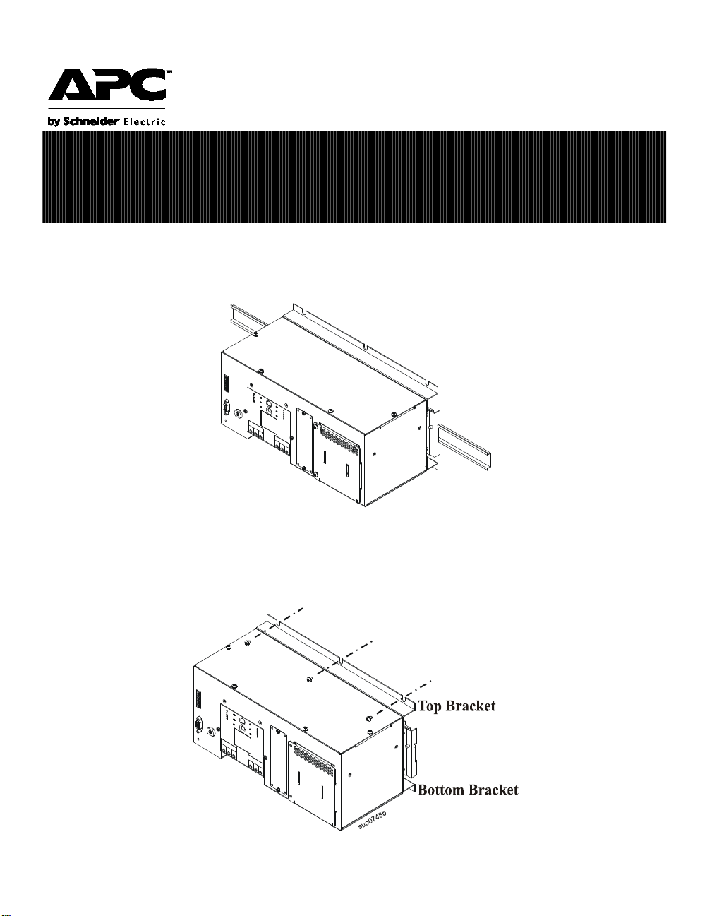
Mount the UPS on DIN Rail
This unit is designed to mount on a heavy duty DIN rail or on the back panel of an enclosure. For details on
DIN rail installation refer to the DIN rail installation guide included in the DIN rail package. The DIN rail kit is
not included.
When mounting on the back panel of an enclosure, select screws that are appropriate for the weight of this unit
and the mounting surface material.
Six screws must be used when mounting this unit in an enclosure. Three screws in the top of the bracket and
three screws in the bottom of the bracket. Failure to follow these instructions may result in damage to the unit.
s
u
o
0
7
4
8
a
Installation and Operation
Smart-UPS
®
SUA500PDR

2
Battery Installation
The UPS battery is shipped in a separate carton.
Refer to the installation guide included with the replacement battery for installation instructions.
Front Panel
Connect Power and Equipment to the UPS
Hardwiring should be performed by a qualified electrician. Use appropriate size wires.
1. The UPS features a transient voltage surge-suppression (TVSS) screw located on the front panel. The
TVSS screw is used for connecting the ground lead on surge suppression devices such as telephone and
network line protectors.
Prior to connecting the grounding cable, ensure that the UPS is NOT connected to utility or battery
power.
2. Hardwire the UPS.
– In 230 V applications the UPS must be protected with a circuit breaker that complies with
European standards for branch rated protection per the country of installation.
– In 208 V applications, the SUA500PDRI must be protected by a dual pole, 10 A branch rated
circuit breaker with UL489 rating.
– The 120 V SUA500PDR has supplementary circuit breaker protection. The unit should be
protected by a single pole, 15 A branch rated circuit breaker with a UL489 rating. Ensure that
the branch circuit breaker is off prior to wiring the unit.
3. Connect equipment to the UPS.
4. Add optional accessories to the SmartSlot located on the front panel.
5. Turn on all connected equipment. To use the UPS as a master on/off switch, be sure all connected
equipment is switched on.
6. Press the Test button on the front panel to start the UPS.
– The battery charges to 90% capacity during the first four hours of normal operation.
– Do not expect full battery run capability during this initial charge period.
7. For optimal computer system security, install PowerChute monitoring software included with the UPS.
PUSH
TO
RESET
1 EPO
2 EPO COM
3 NC
4 COM
5 NO
6 NC
7 COM
8 NO
LOW
BATTERY
ON
BATTERY
INPUT
208/220-240V~ 50/60Hz, 7A MAX
OUTPUT
23
325W, 2.7A MAX
0V~ 50/60Hz, 500VA
L
N
L
N
LINENEUTRALGROUND LINENEUTRALGROUND
Test
suo0746a
120 V model depicted.
INPUT
L1L2/N
OUTPUT
L1
L2/N
INPUT
LN
OUTPUT
LINE
NEUT RAL
LINE
NEUT RAL
L
N
120 V
models
208/230 V
models
3
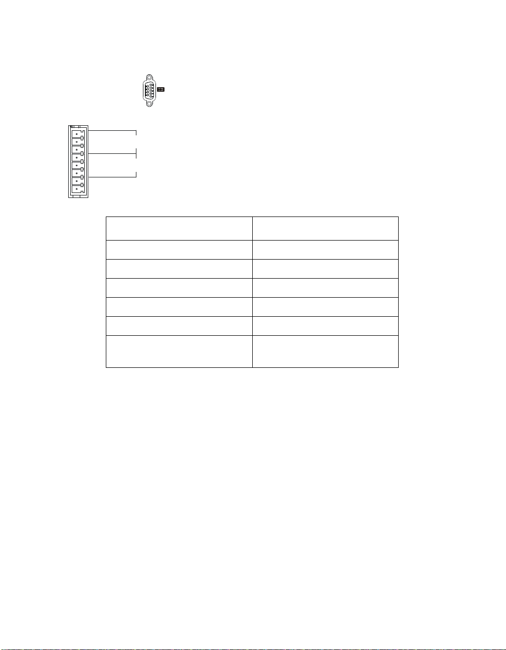
Connectors
Communication Port
Contact Closure Port
Output Contact Ratings:
Emergency Power Off
The emergency power off (EPO) feature is user configurable. EPO provides immediate de-energizing of
connected equipment from a remote location, without switching to battery operation.
Use a normally-open contact to connect the EPO COM terminal to the EPO terminal.
The EPO interface is a Safety Extra Low Voltage (SELV) circuit. Connect it only to other SELV
circuits. The EPO interface monitors circuits that have no determined voltage potential. Such closure
circuits may be provided by a switch or relay properly isolated from the utility. To avoid damage to the
UPS, do not connect the EPO interface to any circuit other than a closure type circuit.
Use one of the following cable types to connect the UPS to the EPO switch.
• CL2: Class 2 cable for general use.
• CL2P: Plenum cable for use in ducts, plenums, and other spaces used for environmental air.
• CL2R: Riser cable for use in a vertical run in a floor-to-floor shaft.
• CLEX: Limited use cable for use in dwellings and for use in raceways.
• For installation in Canada: Use only CSA certified, type ELC (extra-low voltage control cable).
• For installation in other countries: Use standard low-voltage cable in accordance with national and
local regulations.
Parameter Value
nominal switching capacity 1 A @ 30 VDC
maximum switching power 30 W
maximum switching voltage 60 VDC
maximum switching current 2 ADC
maximum carrying current 2 ADC
surge ratings 2 kV per Bellcore TA-NWT-001089
1.5 kV per FCC part 68
SERIAL PORT
A standard serial interface cable is incompatible with the UPS.
Use the cable supplied with the unit.
1 EPO
2 EPO COM
3 NC
4 COM
5 NO
6 NC
7 COM
8 NO
LOW
BATTERY
ON
BATTERY
The relays are connected from the common (COM) to the normally
closed (NC) pins.When the unit enters a low battery or on battery state,
the appropriate relay will transition and connect the common (COM) to
the normally open (NO) pin.
The Contact Closure Port connection will automatically disable when a
Network Management Card or the Serial Port connection are used.
4
Operation
Operation
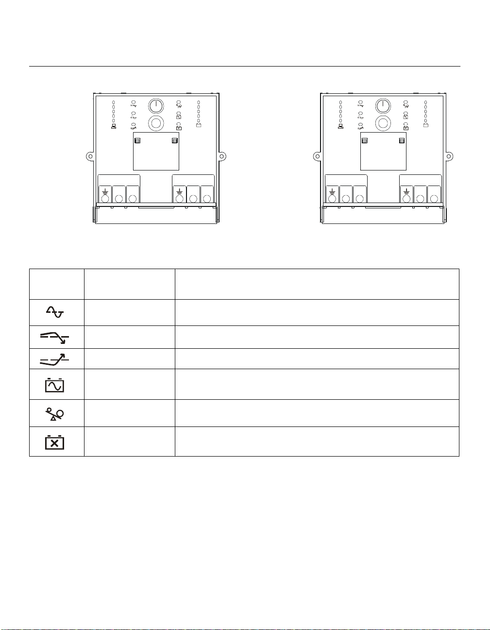
UPS Display Panel
Display Panel Indicators and Function Buttons
Indicator
LED
Indicator Title Description
On-Line The UPS is supplying utility power to the connected equipment
(see Troubleshooting).
AVR Trim The UPS is compensating for a high utility voltage (see Troubleshooting).
AVR Boost The UPS is compensating for a low utility voltage (see Troubleshooting).
On Battery The UPS is supplying battery power to the connected equipment.
Overload The connected equipment is drawing more than the UPS power rating allows
(see Troubleshooting).
Replace Battery/Battery
Disconnected
The battery is disconnected or must be replaced (see Troubleshooting).
INPUT
208/220-240V~ 50/60Hz, 7A MAX
OUTPUT
23
325W, 2.7A MAX
0V~ 50/60Hz, 500VA
L
N
L
N
LINE
NEUTRAL
GROUND
LINE
NEUTRAL
GROUND
Test
suo0745a
INPUT
208/220-240V~ 50/60Hz, 7A MAX
OUTPUT
23
325W, 2.7A MAX
0V~ 50/60Hz, 500VA
L1
L2/N
L1
L2/N
Test
suo0745b
120 V
models
208/230 V
models
5
Operation
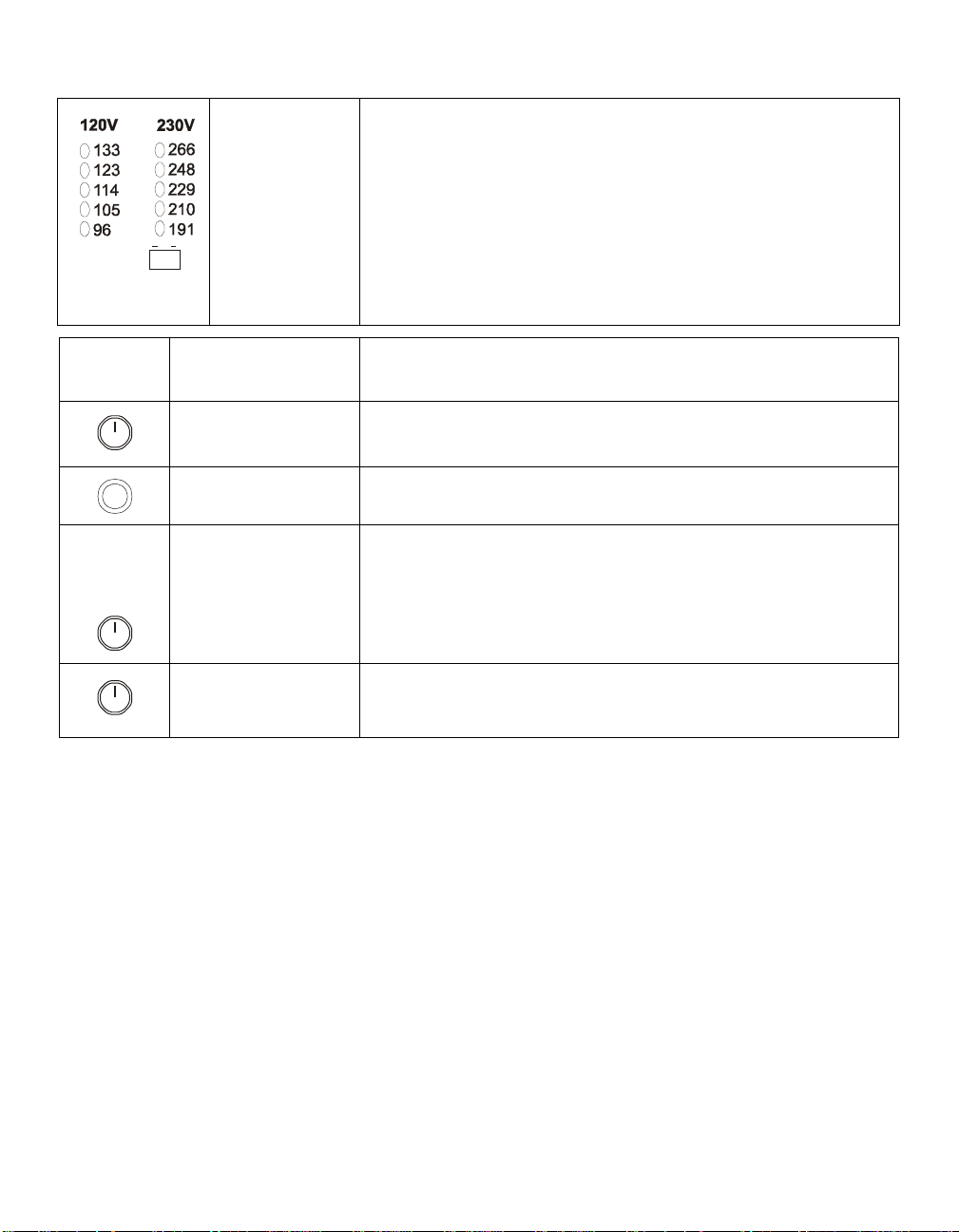
Diagnostic Utility
Voltage
The UPS has a diagnostic feature that indicates the utility voltage.
The UPS starts a self-test as part of this procedure. The self-test does not
affect the voltage display.
Press and hold the Test button to view the utility voltage bar graph indicator.
After a few seconds, this five-LED Battery Charge indicator on the right of
the display panel will show the utility input voltage.
Refer to the figure on the left for the voltage reading (values are not listed on
the UPS).
The indicator on the UPS shows the voltage is between the displayed value
on the list and the next higher value (see Troubleshooting).
Feature
Button
Feature Title Function
Power On Press this button to turn on the UPS. Continue reading for additional
capabilities.
Power Off Press this button to turn off the UPS.
Self-Test Automatic: The UPS performs a self-test automatically when turned on,
and every two weeks thereafter (by default). During the self-test, the UPS
briefly operates the connected equipment on battery.
Manual: Press and hold the
Test
button
for a few seconds to initiate the
self-test.
Cold Start When there is no utility power and the UPS is off, the cold start feature will
switch the UPS and connected equipment onto battery power
(see Troubleshooting).
Battery
Charge
Test
Test
Test
Loading...