


w w w. m g e u p s . c o m
MGE Galaxy 5000
40 – 130KVA
Installation and User Manual
Critical Power and Cooling Services Division

Installation and User Manual
MGE Galaxy 5000
40 – 130KVA
Uninterruptible Power Systems
Installation and User Manual
Schneider Electric
1660 Scenic Avenue, Costa Mesa, CA 92626, (714) 557-1636
Service Solutions Team: 1-800-438-7373 (Hours: 24/7)
Revision History: A00 |
ECN-005986 |
5/28/08 |
B00 |
ECN-006020 |
6/20/08 |
Copyright © 2008 American Power Conversion Corporation. All rights reserved.
Printed in U.S.A.
86-174010-00 B00 |
i |

MGE Galaxy 5000
IMPORTANT SAFETY INSTRUCTIONS
SAVE THESE INSTRUCTIONS – This manual contains important instructions for Galaxy
5000 that must be followed during operation and maintenance of the equipment.
WARNING ATTENTION WARNUNG!
WARNING ATTENTION WARNUNG!
NOTE
WARNING
ATTENTION
WARNUNG!
Opening enclosures expose hazardous voltages. Always refer service to qualified personnel only.
L'ouverture des cellules expose à des tensions dangereuses. Assurez-vous toujours que le service ne soit fait que par des personnes qualifiees.
Das öffnen der Gehäuse legen gefährliche Spannungen bloss. Service sollte immer nur von qualifizierten Personal durchgeführt werden.
As standards, specifications, and designs are subject to change, please ask for confirmation of the information given in this publication.
Comme les normes, spécifications et produits peuvent changer, veuillez demander confirmation des informations contenues dans cette publication.
Normen, Spezifizierungen und Pläne unterliegen Anderungen. Bitte verlangen Sie eine Bestätigung über alle Informationen, die in dieser Ausgabe gemacht wurden.
This equipment has been tested and found to comply with the limits for a Class A digital device, pursuant to part 15 of the FCC rules. These limits are designed to provide reasonable protection against harmful interference when the equipment is operated in a commercial environment.
This equipment generates, uses, and can radiate radio frequency energy and, if not installed and used in accordance with the instruction manual, may cause harmful interference to radio communications. Operation of this equipment in a residential area is likely to cause harmful interference in which case the user will be required to correct the interference at user's own expense.
To reduce the risk of fire or electric shock, install in a controlled indoor environment free of conductive contaminants.
This equipment is intended only for installations in a RESTRICTED ACCESS LOCATION.
Pour réduire le riske d'inccendie ou d'électrocution, installer dans une enciente intérieure contrôlée en température et humidité et sans contaminants conducteurs.
Ce matériel est destiné seulement pour des installations dans un EMPLACEMENT RESTREINT D'ACCES.
Um die Gefahr von Feuer und elektrischem Schock zu reduzieren, muss das Gerät in einem temperatur – und feuchtigkeitskontrollierten Raum, frei von leitungsfähigen Verunreinigungen, installiert werden. Dieses Gerät ist nur für die Installation an einem Ort mit qeingeschränkter Zugangserlaubnis vorgesehen.
Diese Ausrüstung ist nur für Anlagen in einem EINGESCHRäNKTEN ZUGRIFF STANDORT bestimmti.
ii |
Important Safety Instructions |
86-174010-00 B00 |

Installation and User Manual
WARNING
ATTENTION
WARNUNG!
HIGH LEAKAGE CURRENT. Ground connection essential before connecting supply.
COURANT DE FUITE ELEVE. Raccordement a la terre indispensable avant le raccordement au reseau.
Hoher Ableitstrom Vor Inbetriebnahme Schutzleiterverbindung herstellen.
Certification Standards – Three Phase UPS
IEC1004/ANSI C62.41 Standards for Surge Withstand Ability.
FCC Part 15, Subpart J, Class A.
UL/CUL 1778, Standards for Uninterruptible Power Supply Equipment.
NEMA PE 1 - Uninterruptible Power Systems.
NFPA 70 – National Electrical Code.
ISO 9001.
Environment
This product has been designed to respect the environment. It does not contain any Chlorofluorocarbon (CFC) or Hydrochlorofluorocarbon (HCFC).
UPS recycling at the end of service life: Schneider Electric undertakes to recycle, by certified companies and in compliance with all applicable regulations, all UPS products recovered at the end of their service life (contact your Schneider Electric branch office).
Packing: UPS packing materials must be recycled in compliance with all applicable regulations.
WARNING: This product may be supplied with lead-acid batteries. Lead is a dangerous substance for the environment if it is not properly recycled by specialized companies.
86-174010-00 B00 |
Certification Standards, Three Phase UPS, Environment |
iii |

MGE Galaxy 5000
(This page left blank intentionally)
iv |
86-174010-00 B00 |

Contents
IMPORTANT SAFETY INSTRUCTIONS . . . . . . . . . . . . . . . . . . . . . . . . . . . . . . . .ii
Certification Standards – Three Phase UPS . . . . . . . . . . . . . . . . . . . . . . . . . . . . .iii
Environment . . . . . . . . . . . . . . . . . . . . . . . . . . . . . . . . . . . . . . . . . . . . . . . . . . . . . .iii
Contents
CAUTION: Record All Serial Numbers! . . . . . . . . . . . . . . . . . . . . . . . . . . . . . . . . .IV
Safety Rules . . . . . . . . . . . . . . . . . . . . . . . . . . . . . . . . . . . . . . . . . . . . . . . . . . . . . .V
Symbol Usage . . . . . . . . . . . . . . . . . . . . . . . . . . . . . . . . . . . . . . . . . . . . . . . . . . . . .VI
Section Descriptions . . . . . . . . . . . . . . . . . . . . . . . . . . . . . . . . . . . . . . . . . . . . . . .VII
Introduction
1.0 Scope . . . . . . . . . . . . . . . . . . . . . . . . . . . . . . . . . . . . . . . . . . . . . . . . . . . . .1 — 1
1.1 General Description . . . . . . . . . . . . . . . . . . . . . . . . . . . . . . . . . . . . . . . . . .1 — 1 1.2 Inside the UPS Cabinet, Access to Connections . . . . . . . . . . . . . . . . . . . .1 — 3
1.3 UPS Cabinet Bottom View Layout . . . . . . . . . . . . . . . . . . . . . . . . . . . . . . .1 — 4 1.4 User-Machine Interface Display . . . . . . . . . . . . . . . . . . . . . . . . . . . . . . . . .1 — 5 1.5 Display Screens . . . . . . . . . . . . . . . . . . . . . . . . . . . . . . . . . . . . . . . . . . . . .1 — 6 1.6 Relay Communication Card . . . . . . . . . . . . . . . . . . . . . . . . . . . . . . . . . . . .1 — 7
Setup and Installation
2.0 Scope . . . . . . . . . . . . . . . . . . . . . . . . . . . . . . . . . . . . . . . . . . . . . . . . . . . . .2 — 1 2.1 Location . . . . . . . . . . . . . . . . . . . . . . . . . . . . . . . . . . . . . . . . . . . . . . . . . . .2 — 1 2.1.1 Layout of Cabinets . . . . . . . . . . . . . . . . . . . . . . . . . . . . . . . . . . . . . . . . . . .2 — 2 2.2 Electrical Specifications . . . . . . . . . . . . . . . . . . . . . . . . . . . . . . . . . . . . . . .2 — 2 2.3 Connection of Power Cables in a Single UPS . . . . . . . . . . . . . . . . . . . . . .2 — 3 2.4 Redundant Parallel Configuration (Maximum Two UPS Units for Pn) . . . .2 — 4
2.5 Auxiliary Interconnections Between UPSs in Parallel Configurations . . . .2 — 5
2.6Connection of General Shutdown or Remote Emergency Power Off
(REPO) Terminal Block . . . . . . . . . . . . . . . . . . . . . . . . . . . . . . . . . . . . . . .2 — 7
2.7 Adding Communication Cards . . . . . . . . . . . . . . . . . . . . . . . . . . . . . . . . . .2 — 8 2.8 Connection of the Relay Communications Card . . . . . . . . . . . . . . . . . . . .2 — 9
2.8.1Characteristics of the Contacts on the Relay Communications Card . . . .2 — 10
2.9 Routing the Control/Communications Cables . . . . . . . . . . . . . . . . . . . . . .2 — 11
Operation
3.0 |
Scope . . . . . . . . . . . . . . . . . . . . . . . . . . . . . . . . . . . . . . . . . . . . . . . . . . . . |
.3 — 1 |
3.1 |
Shutting Down a Single UPS . . . . . . . . . . . . . . . . . . . . . . . . . . . . . . . . . . . |
3 — 1 |
3.2 |
Restarting a Single UPS . . . . . . . . . . . . . . . . . . . . . . . . . . . . . . . . . . . . . . |
3 — 2 |
3.3 |
Shutting Down a Parallel Configuration . . . . . . . . . . . . . . . . . . . . . . . . . . . |
3 — 2 |
3.4 |
Restarting a Parallel Configuration . . . . . . . . . . . . . . . . . . . . . . . . . . . . . . |
3 — 3 |
3.5 |
Operation of Mimic-Panel LEDs . . . . . . . . . . . . . . . . . . . . . . . . . . . . . . . . |
3 — 4 |
86-174010-00 B00 |
Contents |
I |

MGE Galaxy 5000
3.6 Operating Modes . . . . . . . . . . . . . . . . . . . . . . . . . . . . . . . . . . . . . . . . . . . .3 — 5 3.7 Load on Battery Power . . . . . . . . . . . . . . . . . . . . . . . . . . . . . . . . . . . . . . .3 — 5 3.8 UPS Personalization . . . . . . . . . . . . . . . . . . . . . . . . . . . . . . . . . . . . . . . . .3 — 6 3.9 Display Messages List . . . . . . . . . . . . . . . . . . . . . . . . . . . . . . . . . . . . . . . .3 — 7 3.10 Operation of the Relay Communication Card (Dry Contacts) . . . . . . . . . .3 — 8 3.10.1 Standard Mode . . . . . . . . . . . . . . . . . . . . . . . . . . . . . . . . . . . . . . . . . . . . .3 — 8 3.10.2 Programmable Mode . . . . . . . . . . . . . . . . . . . . . . . . . . . . . . . . . . . . . . . . .3 — 8 3.10.3 List of Operating Status Conditions That May be Assigned to an
SECI Output . . . . . . . . . . . . . . . . . . . . . . . . . . . . . . . . . . . . . . . . . . . . . . . .3 — 9
Maintenance
4.0 Scope . . . . . . . . . . . . . . . . . . . . . . . . . . . . . . . . . . . . . . . . . . . . . . . . . . . . .4 — 1 4.1 Identification of Alarms . . . . . . . . . . . . . . . . . . . . . . . . . . . . . . . . . . . . . . . .4 — 1 4.2 Life Cycle Monitoring (LCM) . . . . . . . . . . . . . . . . . . . . . . . . . . . . . . . . . . .4 — 1 4.3 UPS Isolation . . . . . . . . . . . . . . . . . . . . . . . . . . . . . . . . . . . . . . . . . . . . . . .4 — 2 4.3.1 UPS Isolation Single UPS . . . . . . . . . . . . . . . . . . . . . . . . . . . . . . . . . . . . .4 — 2
4.3.2 UPS Isolation Parallel UPS Without External Bypass Cabinet . . . . . . . . .4 — 3 4.3.3 UPS Isolation Parallel UPS With External Bypass Cabinet . . . . . . . . . . . .4 — 4 4.4 Return to the Normal Operation . . . . . . . . . . . . . . . . . . . . . . . . . . . . . . . . .4 — 5 4.4.1 Return to Normal Single UPS . . . . . . . . . . . . . . . . . . . . . . . . . . . . . . . . . .4 — 5 4.4.2 Return to Normal Parallel UPS Without External Bypass Cabinet . . . . . .4 — 6
4.4.3 Return to Normal Parallel UPS With External Bypass Cabinet . . . . . . . . .4 — 8 4.5 Servicing Batteries . . . . . . . . . . . . . . . . . . . . . . . . . . . . . . . . . . . . . . . . . . .4 — 9
4.6 Training Center . . . . . . . . . . . . . . . . . . . . . . . . . . . . . . . . . . . . . . . . . . . . .4 — 9
Appendices
A1 Electrical Characteristics . . . . . . . . . . . . . . . . . . . . . . . . . . . . . . . . . . . . . .A — 1 A2 Maximum Allowable Power for Parallel UPS Units . . . . . . . . . . . . . . . . . .A — 5
A3 UPS Cabinet Major Internal Components . . . . . . . . . . . . . . . . . . . . . . . . .A — 6 A4 Available Options . . . . . . . . . . . . . . . . . . . . . . . . . . . . . . . . . . . . . . . . . . . .A — 7 A5 Environment . . . . . . . . . . . . . . . . . . . . . . . . . . . . . . . . . . . . . . . . . . . . . . . .A — 8
MGE Warranty & Proprietary Rights Statement for Three Phase Products
MGE Standard Three Phase Warranty . . . . . . . . . . . . . . . . . . . . . . . . . . . . . . . . . .W — 1 Proprietary Rights Statement . . . . . . . . . . . . . . . . . . . . . . . . . . . . . . . . . . . . . . . . .W — 1
Warranty and Product Registration
User Information . . . . . . . . . . . . . . . . . . . . . . . . . . . . . . . . . . . . . . . . . . . . . . . . . |
.W — 2 |
Product Information . . . . . . . . . . . . . . . . . . . . . . . . . . . . . . . . . . . . . . . . . . . . . . . . |
W — 2 |
Warranty Extension (Warranty+) . . . . . . . . . . . . . . . . . . . . . . . . . . . . . . . . . . . . . . . |
W — 2 |
Service Solutions Team — Three Phase Products |
|
Technical Support and Product Services . . . . . . . . . . . . . . . . . . . . . . . . . . . . . . . .S — 1 Who To Contact . . . . . . . . . . . . . . . . . . . . . . . . . . . . . . . . . . . . . . . . . . . . . . . . . . .S — 1
Scheduling Field Service Engineer Support . . . . . . . . . . . . . . . . . . . . . . . . . . . . . .S — 1
Return Policy for Repair of Three Phase Products (RGA) . . . . . . . . . . . . . . . . . . .S — 1
Glossary
Reorder Form
II |
Contents |
86-174010-00 B00 |

Installation and User Manual
Figures
1-1 MGE Galaxy 5000 UPS Cabinet. . . . . . . . . . . . . . . . . . . . . . . . . . . . . . . . .1 — 2 1-2 Single Line Diagram . . . . . . . . . . . . . . . . . . . . . . . . . . . . . . . . . . . . . . . . . .1 — 2 1-3 Inside MGE Galaxy 5000 UPS Cabinet . . . . . . . . . . . . . . . . . . . . . . . . . . .1 — 3 1-4 Power Connection Terminals . . . . . . . . . . . . . . . . . . . . . . . . . . . . . . . . . . .1 — 4 1-5 INTN PCA for Auxiliary Interconnections of Parallel UPSs . . . . . . . . . . . .1 — 4 1-6 MGE Galaxy 5000 Cabinet Bottom View Layout . . . . . . . . . . . . . . . . . . . .1 — 4
1-7 User-Machine Interface Display . . . . . . . . . . . . . . . . . . . . . . . . . . . . . . . . .1 — 5 1-8 Display Screens . . . . . . . . . . . . . . . . . . . . . . . . . . . . . . . . . . . . . . . . . . . . .1 — 6 1-9 Relay Communication Card . . . . . . . . . . . . . . . . . . . . . . . . . . . . . . . . . . . .1 — 7 2-1 Space Allowance for Installation of UPS . . . . . . . . . . . . . . . . . . . . . . . . . .2 — 1 2-2 Layout of Cabinets (typical) . . . . . . . . . . . . . . . . . . . . . . . . . . . . . . . . . . . .2 — 2 2-3 Single UPS With Common Normal and Bypass AC Inputs . . . . . . . . . . . .2 — 3 2-4 Single UPS With Separate Normal and Bypass AC Inputs . . . . . . . . . . . .2 — 3 2-5 Parallel UPS With Common Normal and Bypass AC Inputs . . . . . . . . . . .2 — 4 2-6 Parallel UPS With Separate Normal and Bypass AC Inputs . . . . . . . . . .2 — 4
2-7 Redundant Parallel Configuration (Maximum Two UPS) . . . . . . . . . . . . . .2 — 5 2-8 Parallel Configuration for Increased Capacity (Four UPSs) . . . . . . . . . . .2 — 6 2-9 Fitting the Protection Cover for the Auxiliary Interconnection Cables . . . .2 — 7 2-10 Connection of General Shutdown or Remote Emergency Power Off
(REPO) Terminal Block . . . . . . . . . . . . . . . . . . . . . . . . . . . . . . . . . . . . . . .2 — 7 2-11 Adding Communication Cards . . . . . . . . . . . . . . . . . . . . . . . . . . . . . . . . . .2 — 8 2-12 Connection of Relay Communication Card . . . . . . . . . . . . . . . . . . . . . . . .2 — 9 2-13 Characteristics of the Contacts on the Relay Communications Card . . . .2 — 10 2-14 Routing the Control/Communications Cables for Single UPS . . . . . . . . . .2 — 11 2-15 Routing the Control/Communications Cables for Parallel UPS . . . . . . . . .2 — 12 3-1 Shutting Down a Single UPS . . . . . . . . . . . . . . . . . . . . . . . . . . . . . . . . . . .3 — 1
3-2 Restarting a Single UPS . . . . . . . . . . . . . . . . . . . . . . . . . . . . . . . . . . . . . .3 — 2 3-3 Shutting Down a Parallel Configuration . . . . . . . . . . . . . . . . . . . . . . . . . . .3 — 2 3-4 Restarting a Parallel Configuration . . . . . . . . . . . . . . . . . . . . . . . . . . . . . .3 — 3
3-5 Operation of Mimic-Panel LEDs . . . . . . . . . . . . . . . . . . . . . . . . . . . . . . . .3 — 4 3-6 Normal (Double Conversion) Operating Mode . . . . . . . . . . . . . . . . . . . . .3 — 5 3-7 Load on Battery Power . . . . . . . . . . . . . . . . . . . . . . . . . . . . . . . . . . . . . . .3 — 5 3-8 UPS Personalization . . . . . . . . . . . . . . . . . . . . . . . . . . . . . . . . . . . . . . . . .3 — 6 4-1 Life Cycle Monitoring (LCM) . . . . . . . . . . . . . . . . . . . . . . . . . . . . . . . . . . .4 — 1 4-2 UPS Isolation . . . . . . . . . . . . . . . . . . . . . . . . . . . . . . . . . . . . . . . . . . . . . . .4 — 2 4-3 Parallel UPS Configuration Without External Bypass Cabinet . . . . . . . . .4 — 3
4-4 Parallel UPS Configuration With External Bypass Cabinet . . . . . . . . . . . .4 — 4 4-5 Shutdown and Isolation of all the UPSs . . . . . . . . . . . . . . . . . . . . . . . . . .4 — 4
4-6 Return to the Normal Operation for Single UPS . . . . . . . . . . . . . . . . . . . .4 — 5 4-7 Parallel UPS Configuration Without External Bypass Cabinet . . . . . . . . .4 — 6 4-8 Parallel UPS Configuration With External Bypass Cabinet . . . . . . . . . . . .4 — 8
Tables
2-1 Electrical Specifications for the MGE Galaxy 5000 . . . . . . . . . . . . . . . . . .2 — 2 4-1 Identification of Alarms . . . . . . . . . . . . . . . . . . . . . . . . . . . . . . . . . . . . . . . .4 — 1
86-174010-00 B00 |
Contents |
III |

MGE Galaxy 5000
CAUTION: Record All Serial Numbers!
RECORD ALL SERIAL NUMBERS FOR THE MGE GALAXY 5000 AND ACCESSORIES. THESE SERIAL NUMBERS WILL BE REQUIRED IF YOUR SYSTEM NEEDS SERVICE. KEEP THIS MANUAL IN A PLACE WHERE YOU CAN REFERENCE THE SERIAL NUMBERS IF SERVICE IS REQUIRED!
UPS SERIAL NUMBER: ____________________________________________________________
BATTERY SERIAL NUMBER: _______________________________________________________
AUXILIARY SERIAL NUMBER: ______________________________________________________
ADDITIONAL SERIAL NUMBERS:
____________________________________ ____________________________________
____________________________________ ____________________________________
____________________________________ ____________________________________
____________________________________ ____________________________________
____________________________________ ____________________________________
____________________________________ ____________________________________
____________________________________ ____________________________________
NOTES:
IV |
Record All Serial Numbers |
86-174010-00 B00 |
Installation and User Manual
Safety Rules
Safety of persons
The UPS must be installed in a room with restricted access (qualified personnel only). A UPS has its own external power source (the battery). Consequently, the power outlets may be energized even if the UPS is disconnected from the AC-power source.
Dangerous voltage levels are present within the UPS. It should be opened exclusively by qualified service personnel.
The UPS must be properly grounded.
The battery supplied with the UPS contains small amounts of toxic materials. To avoid accidents, the instructions below must be observed.
Never operate the UPS if the ambient temperature and relative humidity are higher than the levels specified in the documentation.
Never burn the battery (risk of explosion).
Do not attempt to open the battery (the electrolyte is dangerous for the eyes and skin).
Comply with all applicable regulations for the disposal of the battery.
Caution, wait five minutes before opening the UPS to allow the capacitors to discharge.
Caution, there is high leakage current, the grounding conductor must be connected first.
The product must be installed on a non-inflammable surface (e.g. concrete).
Caution, battery replacement must be carried out by qualified personnel.
Product safety
A protection circuit breaker must be installed upstream and downstream, and be easily accessible.
Never install the UPS near liquids or in an excessively damp environment.
Never let a liquid or foreign body penetrate inside the UPS.
Never block the ventilation grates of the UPS.
Never expose the UPS to direct sunlight or a source of heat.
When replacing battery cells, use the same type and number of cells.
Special precautions
The UPS connection instructions contained in this manual must be followed in the indicated order.
Check that the indications on the rating plate correspond to your AC-power system and to the actual electrical consumption of all the equipment to be connected to the UPS.
If the UPS must be stored prior to installation, storage must be in a dry place.
The admissible storage temperature range is -25°C to +45°C.
If the UPS remains de-energized for a long period, we recommend that you energize the UPS for a period of 24 hours, at least every three months. This charges the battery, thus avoiding possible irreversible damage.
The UPS is designed for normal climatic and environmental operating conditions concerning the altitude, ambient
operating temperature, relative humidity and ambient transport and storage conditions.
Using the UPS within the given limits guarantees its operation, but may affect the service life of certain components, particularly that of the battery and its autonomy. The maximum storage time of the UPS is limited due to the need to recharge the battery.
Unusual operating conditions may justify special design or protection measures:
-harmful smoke, dust, abrasive dust,
-humidity, vapor, salt air, bad weather or dripping,
-explosive dust and gas mixture,
-extreme temperature variations,
-bad ventilation,
-conductive or radiant heat from other sources,
-strong electromagnetic fields,
-radioactive levels higher than those of the natural environment,
-fungus, insects, vermin, etc.,
-battery operating conditions.
86-174010-00 B00 |
Safety Rules |
V |
MGE Galaxy 5000
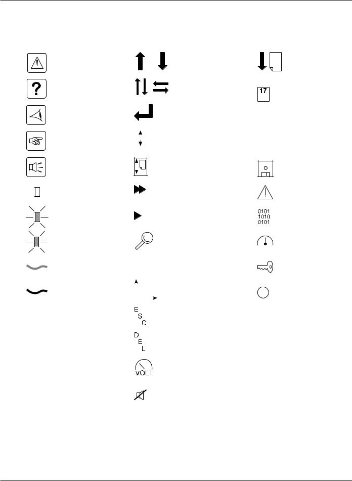
Symbol Usage
Document Icons |
Display Icons |
Danger, these instructions are imperative.
Information, advice, help
Visual indication
Action
Audio signal
LED OFF
LED flashing
LED ON
Ground cables
Other cables
|
|
|
|
|
|
|
|
|
|
Vertical selection |
|
Move up or down one |
||||
|
|
|
|
|
|
|
|
|
|
|
|
|
|
|
|
page |
|
|
|
|
|
|
|
|
|
|
Other selection |
|
Event selection in log |
||||
|
|
|
|
|
|
|
|
|
|
|
may |
|
||||
|
|
|
|
|
|
|
|
|
|
|
|
by date and time |
||||
|
|
|
|
|
|
|
|
|
|
Enter / Confirm |
|
|
||||
|
|
|
|
|
|
|
|
|
|
|
|
|
|
|
|
Increase |
|
|
|
|
|
|
|
|
|
|
|
|
|
|
|
|
|
|
|
|
|
|
|
|
|
|
|
|
|
|
|
|
|
|
|
|
|
|
|
|
|
|
|
|
|
|
|
|
|
|
|
|
|
|
|
|
|
|
|
|
|
Event scroll in log |
|
Decrease |
||||
|
|
|
|
|
|
|
|
|
|
|
||||||
|
|
|
|
|
|
|
|
|
|
|||||||
|
|
|
|
|
|
|
|
|
|
|
|
|
|
|
|
|
|
|
|
|
|
|
|
|
|
|
Page scroll in log |
|
|
|
|||
|
|
|
|
|
|
|
|
|
|
|
|
|
|
Save |
||
|
|
|
|
|
|
|
|
|
|
|
|
|
|
|||
|
|
|
|
|
|
|
|
|
|
|
|
|
||||
|
|
|
|
|
|
|
|
|
|
|||||||
|
|
|
|
|
|
|
|
|
|
|
|
|
|
|
|
|
|
|
|
|
|
|
|
|
|
|
|
|
|
|
|
||
|
|
|
|
|
|
|
|
|
|
|
|
|
|
|
||
|
|
|
|
|
|
|
|
|
|
|
|
|
|
|
|
|
|
|
|
|
|
|
|
|
|
|
Fast forward |
|
Alarm |
||||
|
|
|
|
|
|
|
|
|
|
|
|
|
|
|
|
|
|
|
|
|
|
|
|
|
|
|
Forward |
|
Status conditions |
||||
|
|
|
|
|
|
|
|
|
|
|
|
|
|
|
|
|
|
|
|
|
|
|
|
|
|
|
Details |
|
Settings |
||||
|
|
|
|
|
|
|
|
|
|
|
|
|
|
|
|
|
|
|
|
|
|
|
|
|
|
|
Circular menu |
|
Maintenance |
||||
|
|
|
|
|
|
|
|
|
|
|
||||||
|
|
|
|
|
|
|
|
|
|
|
||||||
|
|
|
|
|
|
|
|
|
|
|
||||||
|
|
|
|
|
|
|
|
|
|
Graphical display |
|
|
|
Control |
||
|
|
|
|
|
|
|
|
|
|
|
|
|
||||
|
|
|
|
|
|
|
|
|
|
|
|
|
||||
|
|
|
|
|
|
|
|
|
|
|
|
|
||||
|
|
|
|
|
|
|
|
|
|
|
||||||
|
|
|
|
|
|
|
|
|
|
Return to previous display |
|
|
||||
|
|
|
|
|
|
|
|
|
|
|
|
|||||
|
|
|
|
|
|
|
|
|
|
Delete |
|
|
||||
|
|
|
|
|
|
|
|
|
|
Access to measurements |
|
|
||||
|
|
|
|
|
|
|
|
|
|
Buzzer off |
|
|
||||
|
|
|
|
|
|
|
|
|
|
|
||||||
VI |
Symbol Usage |
86-174010-00 B00 |

Installation and User Manual
Section Descriptions
1Introduction
Provides a general description of the MGE Galaxy 5000 system’s intended use, single line, major components, and mechanical specifications.
2Setup and Installation
Guides the user through performing connections required for initial installation. Included are the electrical specifications and connection details.
3Operation
Provides startup, shutdown, and normal operation of the MGE Galaxy 5000 UPS. Describes the operation of the mimic-panel LEDs.
4Maintenance
Identifies alarm conditions, UPS isolation operation, and maintenance and safety information on servicing batteries for the MGE Galaxy 5000.
A Glossary provides definitions of abbreviations and terms used in this manual.
86-174010-00 B00 |
Section Descriptions |
VII |

MGE Galaxy 5000
(This page left blank intentionally)
VIII |
86-174010-00 B00 |

Introduction
Thank you for selecting a Schneider Electric product to protect your electrical equipment. The MGE Galaxy 5000 range has been designed with the utmost care. We recommend that you take the time to read this manual to take full advantage of the many features of your UPS. Schneider Electric pays great attention to the environmental impact of its products. Measures that have made MGE Galaxy 5000 a reference in environmental protection include:
the eco-design approach used in product development,
production in an ISO 14001 certified factory,
recycling of the MGE Galaxy 5000 at the end of its service life.
To discover the entire range of Schneider Electric products and the options available for the MGE Galaxy 5000 range, we invite you to visit our web site, www.mgeups.com, or contact your local Schneider Electric representative.
All products in the MGE Galaxy 5000 range are protected by patents. They implement original technology not available to competitors of Schneider Electric.
To take into account evolving standards and technology, equipment may be modified without notice. Indications concerning technical characteristics and dimensions are not binding unless confirmed by Schneider Electric.
This document may be copied only with the written consent of Schneider Electric. Authorized copies must be marked "MGE Galaxy 5000 Installation and User Manual” no. 86-174010-00. We invite you to visit our web site, www.mgeups.com, or contact your local Schneider Electric representative.
1.0Scope
Provides a general description of the MGE Galaxy 5000 system’s intended use, single line major components, and mechanical specifications.
1.1General Description
The MGE Galaxy 5000 is a three phase double conversion uninterruptible power supply (UPS), designed for flexibility to meet a wide range of application requirements. The MGE Galaxy 5000 offers many options to allow you to customize a solution to meet your unique specifications. The options offered include, but are not limited to, adjacent and remote battery cabinets, input and output isolation transformers, distribution options, parallel system bypass cabinets, and a variety of communication cards.
86-174010-00 B00 |
Introduction |
1 — 1 |
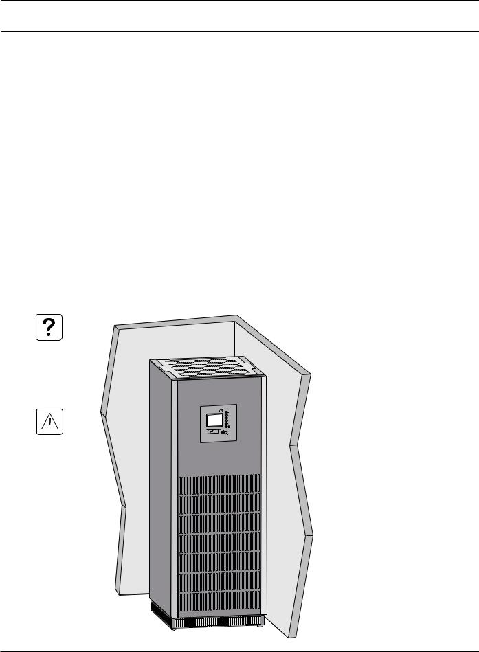
MGE Galaxy 5000
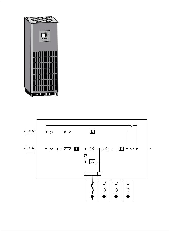
Figure 1-1: MGE Galaxy 5000 UPS Cabinet.
UPS power rating (KVA) |
Dimensions (H x W x D) |
|
|
40-130 |
75” x 28” x 33.4” |
|
1900 x 712 x 850 mm |
|
|
Figure 1-2: Single Line Diagram
MGE GALAXY 5000 UPS SYSTEM WITH BATTERY SINGLE LINE DIAGRAM
|
|
|
|
|
|
|
|
|
Q3BP |
|
|
|
Optional |
Bypass |
Q4S |
KA2 |
|
|
|
|
|
|
|
|
|
Input |
|
|
|
|
|
|
|
|
||||
Bypass |
|
|
|
|
|
|
|
|
||||
|
|
|
|
|
|
|
|
|
|
|
||
Input |
|
|
|
|
|
|
|
|
|
|
|
|
480Y VAC |
|
|
|
Input |
PFC |
|
|
Output |
|
|
|
|
|
|
|
|
|
|
|
|
|
||||
|
Main |
Input |
|
Static |
Boost |
|
Output |
Static |
|
|
|
|
Main |
Q1 Fuses |
KA1 |
Switch |
Rectifier |
Inverter |
Fuses |
Switch |
Q5N |
Output |
To |
||
Input |
||||||||||||
|
||||||||||||
Input |
|
|
|
|
|
|
|
|
|
|
Critical |
|
480 VAC |
|
|
|
Battery |
|
|
|
|
|
|
Load |
|
|
|
|
|
|
|
|
|
|
|
|
Static Switch
Battery
Charger
UPS
CB |
CB |
CB |
CB |
1 — 2 |
Introduction |
86-174010-00 B00 |

Installation and User Manual
1.2Inside the UPS Cabinet, Access to Connections
Figure 1-3: Inside MGE Galaxy 5000 UPS Cabinet

 (1) Connectors for auxiliary interconnections of
  parallel UPS units (INTN PCA), optional
(2) User-machine interface display
(3) Slot for relay communications card
(4) Open slots for optional communication cards
(5) Open cabinet door
(6) Screw-type terminal block for connections of contacts and coils for two external battery circuit breakers XMB07, XMB08
(7) Screw-type terminal block for connection of remote emergency power off (REPO) XMB06
(8) Q1: input switch for normal AC input
(9) Q4S: input switch for bypass AC input
(10) Q3BP: bypass switch
 (11) Q5N: UPS output switch


 (12) Protection cover for power connections
 (13) Screw-type terminal block for connection of contacts for parallel circuit breakers TB6,
  optional
|
|
|
|
|
|
|
|
|
|
|
|
|
|
|
|
|
|
|
|
|
86-174010-00 B00 |
|
|
Introduction |
1 — 3 |
||
MGE Galaxy 5000
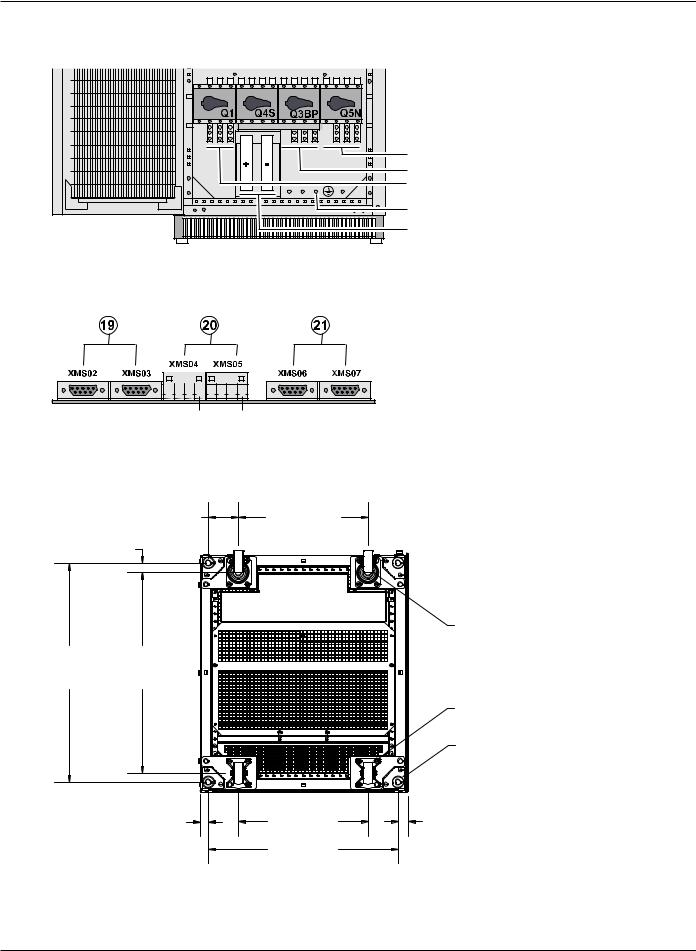
Figure 1-4: Power Connection Terminals
(14) Terminals for load output
(15) Terminals for bypass AC input
(16) Terminals for normal AC input
(17) Main grounding connector
(22) Connection of external battery (+/- poles)
Figure 1-5: INTN PCA for Auxiliary Interconnections of Parallel UPSs
(19) DB9 connectors: exchange-current information
(20) Screw connectors: position information on Q5N, Q4S and Q3BP switches, from the external bypass
(21) DB9 connectors: CAN communication information between UPSs
PIN 1 |
PIN 1 |
1.3UPS Cabinet Bottom View Layout
Figure 1-6: MGE Galaxy 5000 Cabinet Bottom View Layout
4.04 (102.50) |
17.32 (440.00) |
1.26 (32.00)
swivel casters (2)
29.33 |
26.81 |
(745.00) |
(681.00) |
fixed casters (2)
levelers (4)
1.08 (27.50) |
17.32 (440.00) |
1.32 (33.50) |
|
25.39 (645.00) |
|
1 — 4 |
Introduction |
86-174010-00 B00 |
Installation and User Manual
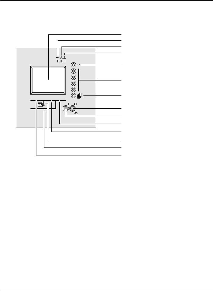
1.4User-Machine Interface Display
Figure 1-7: User-Machine Interface Display
(30) Graphical display
(31) Load protected LED
(32) Minor fault LED
(33) Major fault LED
(34) Help key
(35) Function keys
(36) Menu key
(38) OFF button
(37) ON button
(42) Load supplied LED
(40) UPS ON LED
(41) Operation on battery power LED
(43) Bypass in operation LED
(39) PFC ON LED
86-174010-00 B00 |
Introduction |
1 — 5 |
MGE Galaxy 5000
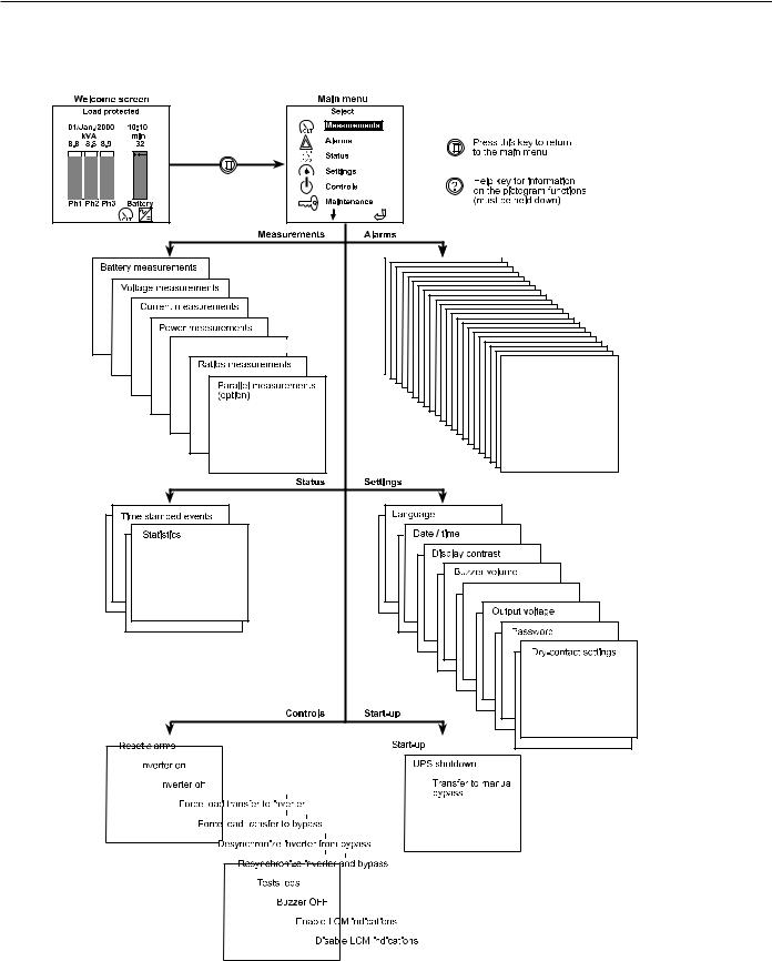
1.5Display Screens
Figure 1-8: Display Screens
Frequency measurements
Personalization
|
|
|
|
|
|
|
|
|
|
|
|
|
|
|
|
|
|
|
|
|
|
|
|
|
|
|
|
|
|
|
|
|
|
|
|
|
|
|
|
|
|
|
|
|
|
|
|
|
|
|
|
|
|
|
|
|
|
|
|
|
|
|
|
|
|
|
|
|
|
|
|
|
|
|
|
|
|
|
|
|
|
|
|
|
|
|
|
|
|
|
|
|
|
|
|
|
|
|
|
|
|
|
|
|
|
|
|
|
|
|
|
|
|
|
|
|
|
|
|
|
|
|
|
|
|
|
|
|
|
|
|
|
|
|
|
|
|
|
|
|
|
|
|
|
|
|
|
|
|
|
|
|
|
|
|
|
|
|
|
|
|
|
|
|
|
|
|
|
|
|
|
|
|
|
|
|
|
|
|
|
|
|
|
|
|
|
|
|
|
|
|
|
|
|
|
|
|
|
|
|
|
|
|
|
|
|
|
|
|
|
|
|
|
|
|
|
|
|
|
|
|
|
|
|
|
|
|
|
|
|
|
|
|
|
|
|
|
|
|
|
|
|
|
|
|
|
|
|
|
|
|
|
|
|
|
|
|
|
|
|
|
|
|
|
|
|
|
|
|
|
|
|
|
|
|
|
|
|
|
|
|
|
|
|
|
|
|
|
|
|
|
|
|
|
|
|
|
|
|
|
|
|
|
|
|
|
|
|
|
|
|
|
|
|
|
|
|
|
|
|
|
|
|
|
|
|
|
|
|
|
|
|
|
|
|
|
|
|
|
|
|
|
|
|
|
|
|
|
|
|
|
|
|
|
|
|
|
|
|
|
|
|
|
|
|
|
|
|
|
|
|
|
|
|
|
|
|
|
|
|
|
|
|
|
|
|
|
|
|
|
|
|
|
|
|
|
|
|
|
|
|
|
|
|
|
|
|
|
|
|
|
|
|
|
|
|
|
|
|
|
|
|
|
|
|
|
|
|
|
|
|
|
|
|
|
|
|
|
|
|
|
|
|
|
|
|
|
|
|
|
|
|
|
|
|
|
|
|
|
|
|
|
|
|
|
|
|
|
|
|
|
|
|
|
|
|
|
|
|
|
|
|
|
|
|
|
|
|
|
|
|
|
|
|
|
|
|
|
|
|
|
|
|
|
|
|
|
|
|
|
|
|
|
|
|
|
|
|
|
|
|
|
|
|
|
|
|
|
|
|
|
|
|
|
|
|
|
|
|
|
|
|
|
|
|
|
|
|
|
|
|
|
|
|
|
|
|
|
|
|
|
|
|
|
|
|
|
|
|
|
|
|
|
|
|
|
|
|
|
|
|
|
|
|
|
|
|
|
|
|
|
|
|
|
|
|
|
|
|
|
|
|
|
|
|
|
|
|
|
|
|
|
|
|
|
|
|
|
|
|
|
|
|
|
|
|
|
|
|
|
|
|
|
|
|
|
|
|
|
|
|
|
|
|
|
|
|
|
|
|
|
|
|
|
|
|
|
|
|
|
|
|
|
|
|
|
|
|
|
|
|
|
|
|
|
|
|
|
|
|
|
|
|
|
|
|
|
|
|
|
|
|
|
|
|
|
|
|
|
|
|
|
|
|
|
|
|
|
|
|
|
|
|
|
|
|
|
|
|
|
|
|
|
|
|
|
|
|
|
|
|
|
|
|
|
|
|
|
|
|
|
|
|
|
|
|
|
|
|
|
|
|
|
|
|
|
|
|
|
|
|
|
|
|
|
|
|
|
|
|
|
|
|
|
|
|
|
|
|
|
|
|
|
|
|
|
|
|
|
|
|
|
|
|
|
|
|
|
|
|
|
|
|
|
|
|
|
|
|
|
|
|
|
|
|
|
|
|
|
|
|
|
|
|
|
|
|
|
|
|
|
|
|
|
|
|
|
|
|
|
|
|
|
|
|
|
|
|
|
|
|
|
|
|
|
|
|
|
|
|
|
|
|
|
|
|
|
|
|
|
|
|
|
|
|
|
|
|
|
|
|
|
|
|
|
|
|
|
|
|
|
|
|
|
|
|
|
|
|
|
|
|
|
|
|
|
|
|
|
|
|
|
|
|
|
|
|
|
|
|
|
|
|
|
|
|
|
|
|
|
|
|
|
|
|
|
|
|
|
|
|
|
|
|
|
|
|
|
|
|
|
|
|
|
|
|
|
|
|
|
|
|
|
|
|
|
|
|
|
|
|
|
|
|
|
|
|
|
|
|
|
|
|
|
|
|
|
|
|
|
|
|
|
|
|
|
|
|
|
|
|
|
|
|
|
|
|
|
|
|
|
|
|
|
|
|
|
|
|
|
|
|
|
|
|
|
|
|
|
|
|
|
|
|
|
|
|
|
|
|
|
|
|
|
|
|
|
|
|
|
|
|
|
|
|
|
|
|
|
|
|
|
|
|
|
|
|
|
|
|
|
|
|
|
|
|
|
|
|
|
|
|
|
|
|
|
|
|
|
|
|
|
|
|
|
|
|
|
|
|
|
|
|
|
|
|
|
|
|
|
|
|
|
|
|
|
|
|
|
|
|
|
|
|
|
|
|
|
|
|
|
|
|
|
|
|
|
|
|
|
|
|
|
|
|
|
|
|
|
|
|
|
|
|
|
|
|
|
|
|
|
|
|
|
|
|
|
|
|
|
|
|
|
|
|
|
|
|
|
|
|
|
|
|
|
|
|
|
|
|
|
|
|
|
|
|
|
|
|
|
|
|
|
|
|
|
|
|
|
|
|
|
|
|
|
|
|
|
|
|
|
|
|
|
|
|
|
|
|
|
|
|
|
|
|
|
|
|
|
|
|
|
|
|
|
|
|
|
|
|
|
|
|
|
|
|
|
|
|
|
|
|
|
|
|
|
|
|
|
|
|
|
|
|
|
|
|
|
|
|
|
|
|
|
|
|
|
|
|
|
|
|
|
|
|
|
|
|
|
|
|
|
|
|
|
|
|
|
|
|
|
|
|
|
|
|
|
|
|
|
|
|
|
|
|
|
|
|
|
|
|
|
|
|
|
|
|
|
|
|
|
|
|
|
|
|
|
|
|
|
|
|
|
|
|
|
|
|
|
|
|
|
|
|
|
|
|
|
|
|
|
|
|
|
|
|
|
|
|
|
|
|
|
|
|
|
|
|
|
|
|
|
|
|
|
|
|
|
|
|
|
|
|
|
|
|
|
|
|
|
|
|
|
|
|
|
|
|
|
|
|
|
|
|
|
|
|
|
|
|
|
|
|
|
|
|
|
|
|
|
|
|
|
|
|
|
|
|
|
|
|
|
|
|
|
|
|
|
|
|
|
|
|
|
|
|
|
|
|
|
|
|
|
|
|
|
|
|
|
|
|
|
|
|
|
|
|
1 — 6 |
|
|
|
|
|
|
|
|
|
|
|
|
|
|
|
|
|
|
|
|
|
|
|
|
|
|
|
|
|
|
|
|
|
|
|
|
|
|
|
Introduction |
|
|
|
|
|
86-174010-00 B00 |
|||||||||||||||
Installation and User Manual
1.6Relay Communication Card
Figure 1-9: Relay Communication Card
(50) Card cover screws
(51) Card screw holes
(52) Card cover
(53) Cable entry holes
(54) Output terminal block
(55) Input terminal block
(56) Cable clamping screws
86-174010-00 B00 |
Introduction |
1 — 7 |

MGE Galaxy 5000
(This page left blank intentionally)
1 — 8 |
Introduction |
86-174010-00 B00 |
Setup and Installation
2.0Scope
Guides the user through performing connections required for initial installation. Included are the electrical specifications and connection details.
2.1Location
To ensure correct ventilation, leave nothing on top of the UPS. Leave three feet of free space in front of the UPS for door opening.
The UPS cabinet rests on four levelers positioned in the four corners of the cabinet to spread the weight. The UPS must be installed in a room with restricted access (qualified personnel only).
Figure 2-1: Installation of UPS
86-174010-00 B00 |
Setup and Installation |
2 — 1 |
 Loading...