


A3.130921
ALINCO, INC.
Yodoyabashi Dai-bldg 13F
4-4-9 Koraibashi, Chuo-ku, Osaka 541-0043 Japan Phone: +81-6-7636-2362 Fax: +81-6-6208-3802 http://www.alinco.com
E-mail:export@alinco.co.jp
DR-138: VHF FM Transceiver 136.000-173.995MHz
DR-438: UHF FM Transceiver 400.000-469.995MHz
All EU and EFTA member states.
Operator license is required.
Copyright Alinco, lnc. PS0665B/FNEG-NL
Printed in China

VHF FM Mobile Transceiver
DR-138
UHF FM Mobile Transceiver
DR-438
Instruction Manual
Thank you for purchasing your new Alinco transceiver. Please read this manual carefully before using the product to ensure full performance, and keep this manual for future reference as it contains information on after-sales services. In case addendum or errata sheets are included with this product, please read those materials and keep them together with this instruction manual for future reference.
NOTE: DR-138/DR-438 may be delivered to you after dealerprogramming. In such cases, please ask your dealer about the available features in your unit and how to operate this unit.
Introduction
Thank you very much for purchasing this excellent Alinco transceiver. Our products are ranked among the finest in the world. This radio has been manufactured with state of the art technology and it has been tested carefully at our factory. It is designed to operate to your satisfaction for many years under normal use.
Please read this manual completely from the first page to the last, to learn all the functions the product offers. It is important to note that some of the operations may be explained in relation to information in previous chapters. By reading just one part of the manual, you may risk not understanding the complete explanation of the function.
Before transmitting
There are many radio stations operating in proximity to the frequency ranges this product covers. Be careful not to cause interference when transmitting around such radio stations.
■ Lightning
Please note that no car provides adequate protection of its passengers or drivers against lightning. Therefore, Alinco will not take responsibility for any danger associated with using its radios or inside the car during lightning.
■ For North American users
Due to strict rules, this product is blocked for operations before sales and only dealers can program the radio before delivery to consumers. Manufacturer is not aware of details of such dealer-programming therefore please kindly contact your dealer first in case technical-service may be necessary.
Features
■Output power selectable (Hi/Mid/Lo)
■PC-programmable
■Alphanumeric name tags
■Voice Compander (Reduce Noise & enhance audio clarity)
■Optional Inversion Scramble (DR-138S/438S only)
■Sub-tone (CTCSS/DCS) Encode/Decode, DTMF/ANI,
2-tone and 5-tone
■Various scan modes, Key lock, Wide/Narrow operations and more at NO extra costs.
Conformity Symbols
Tested to comply MIL-STD-810G
-Shock: Method 514.6/I,IV -Vibration: Method 516.6/I
Conformity Information
In case the unit you have purchased is marked with a CE symbol, a copy of relative conformity certificate or docu-ment can be reviewed at http:// www.alinco.com/usa.html. Please see the back-cover for more details.
Copyright 2012 All rights reserved. NO part of this document may be reproduced, copied, translated or transcribed in any form or by any means without the prior writhout the prior written permission of Alinco.
Inc, Osaka, Japan, English Edition Printed in China.

SAFETY TRAINING INFORMATION
WARNING:
This radio generates RF electromagnetic energy during transmission. This radio is designed for and classified as “Occupational Use Only”, meaning it must be used only during the course of employment by individuals aware of the hazards, and the ways to minimize such hazards. This radio is NOT intended for use by the “GeneralPopulation” in an uncontrolled environment.
• For compliance with FCC and Industry Canada RF Exposure Requirements, the transmitter antenna installation shall comply with the following two conditions:
1.The transmitter antenna gain shall not exceed 0 dBi.
2.The antenna is required to be located outside of a vehicle and kept at a distance of 63 centimeters or more between the transmitting antenna of this device and any persons during operation. For small vehicle as worst case, the antenna shall be located on the roof top at any place on the centre line along the vehicle in order to achieve 63 centimeters separation distance. In order to ensure this distance is met, the installation of the antenna must be mounted at least 63 centimeters away from the nearest edge of the vehicle in order to protect against exposure to bystanders.
CAUTION:
To ensure that your exposure to RF electromagnetic energy is within the FCC allowable limits for occupational use, always adhere to the following guidelines:
• DO NOT operate the radio without a proper antenna attached, as this may damage the radio and may also cause you to exceed FCC RF exposure limits. A proper antenna is the antenna supplied with this
radio by the manufacturer or an antenna specifically authorized by the manufacturer for use with this radio.
• DO NOT transmit for more than 50% during the time of employment
(50% duty cycle or less). Transmitting excessive amount of time can cause RF exposure compliance requirements to be exceeded. Please carefully read this instruction manual to learn how to transmit and stop transmitting before starting to use it.
Electromagnetic Interference/Compatibility
During transmissions, your radio generates RF energy that can possibly cause interference with other devices or systems. To avoid such interference, turn off the radio in areas where signs are posted to do so. DO NOT operate the transmitter in areas that are sensitive to electromagnetic radiation such as hospitals, aircraft, and blasting sites.
Occupational/Controlled Use
This product is used in situations that users are exposed to RF as consequence of their employment provided those users are fully aware of the potential RF hazards and can exercise control over their exposure.
•This transceiver is NOT ATEX approved and NOT intended for the use in hazardous explosive atmospheres.
FCC INFORMATION
FOR CLASS B UNINTENTIONAL RADIATORS:
This equipment has been tested and found to comply with the limits for a Class B digital device, pursuant to part 15 of the FCC Rules.
These limits are designed to provide reasonable protection against harmful interference in a residential installation.
This equipment generates, uses and can radiate radio frequency energy and, if not installed and used in accordance with the instructions, may cause harmful interference to radio communications. However, there is no guarantee that interference will not occur in a particular installation.
If this equipment does cause harmful interference to radio or television reception, which can be determined by turning the equipment off and on, the user is encouraged to try to correct the interference by one or more of the following measures:
●● Reorient or relocate the receiving antenna.
●● Increase the separation between the equipment and receiver.
●● Connect the equipment into an outlet on a circuit different from that to which the receiver is connected.
●● Consult the dealer or an experienced radio/TV technician for help.
For Customers in Canada :
Le présent appareil est conforme aux CNR d'Industrie Canada applicables aux appareils radio exempts de licence.
L'exploitationestautoriséeauxdeuxconditionssuivantes:
(1)l'appareil ne doit pas produire de brouillage, et
(2)l'utilisateur de l'appareil doit accepter tout brouillage radioélectrique subi, même si le brouillage est susceptible d'en compromettre le fonctionnement.
PRECAUTIONS:
The manufacturer declines any responsibilities against loss of life and property due to a failure of this product when used with or as a part of a device made by third parties.
Use of third party accessory may result in damage to this product. It will void our warranty for repair.
 Handling this product
Be sure to reduce the audio output level to minimum before using an earphone or a headset. Excessive audio may damage hearing.
Do not open the unit without permission or instruction from the manufacturer. Unauthorized modification or repair may result in electric shock, fire and/or malfunction and voids warranty.
Do not operate this product in a wet place such as in a shower room. It may result in electric shock, fire and/or malfunction.
Do not place the product in a container carrying conductive materials, such as water or metal in close proximity. A short-circuit to the product may
result in electric shock, fire and/or malfunction.
 In case of emergency
In case of the following situation(s), please turn off the product, switch off the source of power, then remove or unplug the powercord. Please contact your local dealer of this product for service and assistance. Do not use the product until the trouble is resolved. Do not try to troubleshoot the problem by yourself.
●● When a strange sound, smoke and/or strange odor comes out of the product.
●● When the product is dropped or the case is broken or cracked. ●● When a liquid penetrated inside.
●● When a power cord (including DC cables, AC cables and adapters) is damaged
For your safety, turn off then remove all related AC lines to the product and its accessories from the wall outlet if a thunderstorm is likely.
 Maintenance
Do not open the unit and its accessories. Please consult with your local dealer of this product for service and assistance
 Alert
Alert
 Environment and condition of use
It is recommended that you check local traffic regulations regarding the use of a radio equipment while driving. Some countries prohibit or apply restrictions for the operation of radios and mobilephones while driving.
Do not use this product in close proximity to other electronic devices, especially medical ones. It may cause interference to those devices.
Keep the radio out of the reach of children. This product is not a toy and contains small part that may be dangerous when swallowed.
In case a liquid leaks from the product, do not touch it. It may damage your skin. Rinse with plenty of cold water if the liquid contacted your skin.
Never operate this product in facilities where radio products are prohibited for use such as aboard aircraft, in airports, in ports, within or near the operating area of business wireless stations or their relay stations.
Use of this product may be prohibited or illegal outside of your country. Be informed in advance when you travel.
The manufacturer declines any responsibilities against loss of life and/or a property due to a failure of this product.
Do not use multiple radios in very close proximity. It may cause interference and/or damage to the product(s).
 Alert
Alert
 Environment and condition of use
Do not use the product in proximity to a TV or a radio. It may cause interference or receive interference.
Do not install in a humid, dusty or insufficiently ventilated place. It may result in electric shock, fire and/or malfunction.
Do not install in an unstable or vibrating position. It may result in electric shock, fire and/or malfunction when/if the product falls to the ground.
Do not install the product in proximity to a source of heat and humidity such as a heater or a stove. Avoid placing the unit in direct sunlight.
Be cautious of a dew formation. Please completely dry the product before use when it happens.
 About transceiver
Do not connect devices other than specified ones to the jacks and ports on the product. It may result in damage to the devices.
Turn off and remove the power source (AC cable, DC cable, battery, cigar cable, charger adapter etc.) from the product when the product is not in use for extended period of time or in case of maintenance.
Use a clean, dry cloth to wipe off dirt and condensation from the surface of the product. Never use thinner or benzene for cleaning.
Check with your local waste officials for details on recycling or proper disposal in your area.
 PC PROGRAMMING
NOTE: The utility software may be available to distributors/dealers only. USB programming cable is required. The manufacturer will not release the software to unauthorized party so please contact your dealer for details.

CONTENTS
Supplied Accessories/Optional Accessories..................... |
1 |
Supplied Accessories....................................................................... |
1 |
Initial Installation................................................................... |
2 |
Mobile installation............................................................................. |
2 |
DC Power Cable Connection............................................................ |
3 |
Power supply voltage Display........................................................... |
5 |
Antenna Connection......................................................................... |
5 |
Accessories Connections................................................................. |
5 |
Getting Acquainted............................................................... |
7 |
Front panel....................................................................................... |
7 |
Rear panel........................................................................................ |
8 |
Display.............................................................................................. |
8 |
Microphone ...................................................................................... |
9 |
Operating Mode......................................................................... |
10 |
Basic Operations .................................................................. |
11 |
Switching the Power On/Off ............................................................ |
11 |
Adjusting the Volume ....................................................................... |
11 |
Switch between VFO and Channel mode ........................................ |
11 |
Adjusting Frequency/Channel Through Selector Knob.................... |
11 |
Adiusting squelch level..................................................................... |
11 |
Receiving.......................................................................................... |
11 |
Transmitting...................................................................................... |
11 |
Transmitting Tone Burst Tone........................................................... |
12 |
Transmitting Optional Signaling........................................................ |
12 |
Memory Channel Programming........................................................ |
12 |
Memory Channel DeletIng................................................................ |
12 |
KEY OPERATIONS................................................................ |
13 |
Squelch Off/Squelch Off Momentarry............................................... |
13 |
Frequency/Memory Scan................................................................. |
13 |
Memory Scan................................................................................... |
13 |
CTCSS/DCS Encode and Decode setup......................................... |
13 |
CTCSS SCAN.................................................................................. |
14 |
DCS SCAN....................................................................................... |
14 |
High/Mid/Low Power switch.............................................................. |
14 |
Compander....................................................................................... |
14 |
Offset Direction and offset frequency setup...................................... |
14 |
Keypad Lockout................................................................................ |
15 |
Auto-Dialer Setup............................................................................. |
15 |
Transmitting Edited DTMF Tones in the Auto-dialer Memory........... |
15 |
Emergency Alarm............................................................................. |
15 |
PARAMETER SETTING MODE............................................. |
16 |
Frequency Channel Step Setup....................................................... |
16 |
DTMF, DTMF ANI, 2Tone or 5Tone Signaling................................... |
16 |
Sending 2-Tone Call......................................................................... |
17 |
Sending 5-Tone Call......................................................................... |
17 |
Sending DTMF call........................................................................... |
17 |
Signaling Combination setup............................................................ |
17 |
High/Mid/Low Power Selection......................................................... |
18 |
Band-width Selection........................................................................ |
18 |
TX OFF Setup.................................................................................. |
18 |

CONTENTS
Busy Channel Lockout...................................................................... |
19 |
Editing Channel NAME .................................................................... |
19 |
Reverse TX/RX................................................................................. |
19 |
Talk Around ...................................................................................... |
20 |
Voice Compander ............................................................................ |
20 |
Scrambler setup (Encryption)........................................................... |
20 |
Radio's DTMF Self ID Enquiry.......................................................... |
20 |
Radio's 5TONE Self ID Enquiry........................................................ |
20 |
Beep Sound...................................................................................... |
21 |
TOT (Time-out timer)........................................................................ |
21 |
APO (Auto power off)....................................................................... |
21 |
DTMF Transmitting Time.................................................................. |
21 |
Display Iiiumination Color Setting..................................................... |
22 |
Scan Resume Time Setup................................................................ |
22 |
LCD Dimmer..................................................................................... |
22 |
Tone-burst Tones.............................................................................. |
22 |
Display Mode Setup......................................................................... |
22 |
PIN Setup(Useless if PIN is not assigned)................................. |
23 |
Address list ...................................................................................... |
23 |
RESET (May be blocked for dealer-programmed units).......... |
23 |
Microphone Operation.......................................................... |
24 |
Keypad Lock..................................................................................... |
24 |
Transmitting DTMF By Microphone KeyPAD.................................... |
24 |
Function Setup By Microphone Keypad........................................... |
24 |
Switches between VFO and channel mode ..................................... |
24 |
Short Calling .................................................................................... |
24 |
Frequency Step ............................................................................... |
24 |
Optional signaling ............................................................................ |
24 |
Scan Skip ........................................................................................ |
25 |
Frequency/Channel scan ................................................................. |
25 |
Busy Channel Lockout...................................................................... |
25 |
Reverse TX/RX................................................................................. |
25 |
TOT (Time-out timer)........................................................................ |
25 |
CTCSS/DCS Encode and Decode................................................... |
25 |
Talk Around ...................................................................................... |
26 |
Beep Sound...................................................................................... |
26 |
HIGH/MID/LOW Power Selection..................................................... |
26 |
LCD Backlight ................................................................................. |
26 |
Anti-theft Alarm .................................................................... |
27 |
Cable Clone........................................................................... |
28 |
Maintenance.......................................................................... |
29 |
Default Setting after Resetting(DR-138)........................................... |
29 |
Default Setting after Resetting(DR-438)........................................... |
29 |
Trouble Shooting.............................................................................. |
29 |
Specifications DR-138.......................................................... |
30 |
Specifications DR-438.......................................................... |
31 |
Appendix................................................................................ |
32 |
50 groups CTCSS Tone Frequency(Hz)........................................... |
32 |
1024 groups DCS Code................................................................... |
32 |
1 Supplied Accessories
 SUPPLIED ACCESSORIES
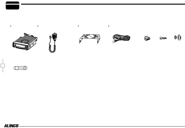
Carefully unpack to make sure the following items are found in the package in addition to this manual:
Transceiver |
Microphone EMS-74 |
Mobile Mounting |
DC Power Cable with |
DR-138/DR-438 |
(with DTMF keyboard) |
Bracket |
Fuse Holder |
 Spare Fuses
1
The standard accessories may vary slightly depending on the version you have purchased. Please contact your local authorized Alinco dealer should you have any questions. Alinco and authorized dealers are not responsible for any typographical errors there may be in this manual. Standard accessories may change without notice.
Warranty Policy: Please refer to any enclosed warranty information or contact your authorized Alinco dealer / distributor for the warranty policy.
 Hardware Kit for Bracket
Black screws |
Tapping screws |
S-Washer |
(M4X8mm) |
(M5X8mm) |
|
4PCS |
4PCS |
|
■In order to operate this product, a properly tuned antenna, its feedline with connectors and fixing hardware are necessary. Please consult with your dealer for details.
 MOBILE INSTALLATION
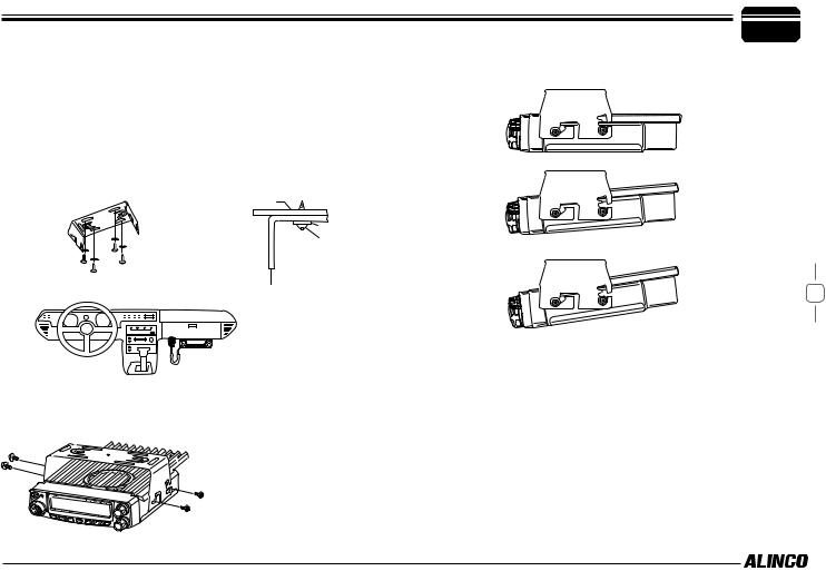
The transceiver may be installed in any position in your car, where the controls and microphone are easily accessible and it does not interfere with the safe operation of the vehicle. If your vehicle is equipped with air bags, be certain your radio will not interfere with their deployment. If you are uncertain about where to mount the unit, contact your vehicle's dealer.
1.Install the mounting bracket in the vehicle using the supplied selftapping screws (4pcs) and flat washers (4pcs).
Car body
Washer (M5) Tapping screw (M5x20mm)
Mounting bracket
2.Position the transceiver, then insert and tighten the supplied hexagon SEMS screws.
Double check that all screws are tightened to prevent vehicle vibration from loosening the bracket or transceiver.
Caution:
Use only the provided screws otherwise you risk damaging the circuit board, components or fall-off of the unit.
Initial Installation 2
Determine the appropriate angle of the transceiver, using the 3 screw hole positions on the side of the mounting bracket.
2
2 |
Initial Installation |
|
 DC POWER CABLE CONNECTION
 MOBILE OPERATION
The vehicle battery must have a nominal rating of 12V. Never connect the transceiver to a 24V battery. Be sure to use a 12V vehicle battery that has sufficient current capacity. If the current to the transceiver is insufficient, the display may darken during transmission, or transmitting output power may drop excessively.
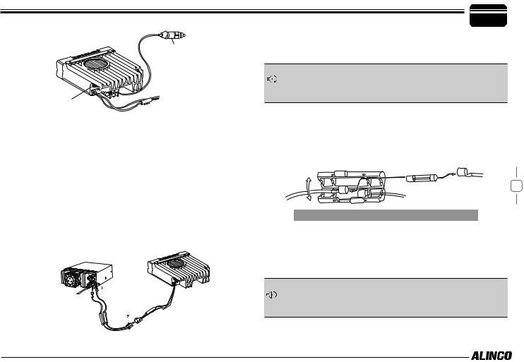
111Route the DC power cable supplied with the transceiver directly to the vehicle's battery terminals using the shortest path from the transceiver.
Never use the cigarette lighter socket as a DC source.
The entire length of the cable must be dressed so it is isolated from heat, moisture, and the engine secondary (high voltage) ignition system/ cables.
3222After installing cable, in order to avoid the risk of damp, please use heat-resistant tap to tie together with fuse box. Don't forget to reinforce whole cable.
333In order to avoid the risk of short circuit, please cut down connection with negative (-) of battery, then connect with radio.
444Confirm the correct polarity of the connections, then attach the power cable to the battery terminals; red connects to the positive (+) terminal and black connects to the negative (-) terminal.
Never remove the fuse holders from the cable.
555Reconnect any wiring removed from the negative terminal.
Red
666Connect the DC power cable to the transceiver's power supply
connector.
Press the connectors firmly together until the locking tab clicks.
DC power cable
Ext. Power jack
If the ignition-key on/off feature is desired(optional feature), use the optional EDC-43(For Cigar-Plug connection) cable. Connect one of the cables between the ACC terminal or a Cigar-Plug that operates with the vehicle ignition or ACC switch on the vehicle and EXT POWER jack on the rear side of the unit.
777When the ignition key is turned to ACC or ON(Start) position with the radio turned off, the power switch illuminates. The illumination will be turned off when the ignition key is turned to the off position.
To turn on the unit, press the power switch manually while it is illuminated. (While ignition key is at ACC or ON position)
888When the ignition key is turned to ACC or ON position with the radio's power switch on, the unit turns on automatically and the power switch will be lit. Turn the ignition key to OFF position or manually turn the power switch off to shut down the radio.
999Use of ignition-key ON/OFF feature drains 5mAh of current from the battery as long as the EDC-43 is being connected.
Black
 ACC terminal
Cigar-Plug connection
Optional EDC-43 required
Ext. Power jack
 FIXED STATION OPERATION
In order to use this transceiver for fixed station operation, you will need a separate 13.8V DC power supply (not included) , Please contact local dealer to require.
The current capacity of your power supply must be 12A or more.
111Connect the DC power cable to the regulated DC power supply and ensure that the polarities are correct. (Red: positive, Black: negative).
Never directly connect the transceiver to an AC outlet.
Use the supplied DC power cable to connect the transceiver to a regulated power supply.
Do not substitute a cable with smaller gauge wires.
Regulated  power supply
Red
Black
Initial Installation |
2 |
|
222Connect the transceiver's DC power connector to the connector on the DC power cable.
Press the connectors firmly together until the locking tab clicks.
Before connecting the DC power to the transceiver, be sure to switch
the transceiver and the DC power supply OFF.
 Do not plug the DC power supply into an AC outlet until you make all connections.
 REPLACING FUSES
If the fuse blows,determine the cause, then correct the problem. After the problem is resolved, replace the fuse. If newly installed fuses continue to blow, disconnect the power cable and contact your dealer for assistance.
4
Fuse Location |
Fuse Current Rating |
|
Transceiver |
15A |
|
Supplied Accessory DC |
20A |
|
power cable |
||
|
Only use fuses of the specified type and rating, otherwise the transceiver could be damaged.
If you use the transceiver for a long period when the vehicle battery is  not fully charged, or when the engine is OFF, the battery may become
  discharged, and will not have sufficient reserves to start the vehicle. Avoid
using the transceiver in these conditions.
DC power cable with fuse holder
2 |
Initial Installation |
|
 POWER SUPPLY VOLTAGE DISPLAY
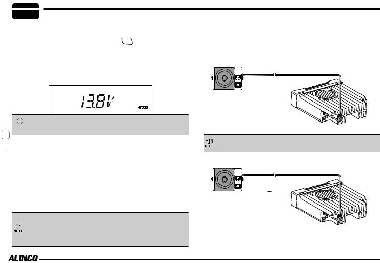
After connecting the transceiver to the power supply, the supply voltage can be displayed on LCD by pressing the 
 key together with the
 key.
key.
The display immediately changes as the voltage supply changes, It also displays voltage during transmission.
The transceiver will return to its normal operation when the power is turned ON/OFF or repeat above operation.
|
The range of displayed voltage is from 7V to16V DC. Because the |
|
Important displayed value is estimated, please use a voltmeter when a more precise |
5 |
reading is desired. |
|
 ANTENNA CONNECTION
Before operating, install an efficient, well-tuned antenna. The success of your installation will depend on the type of antenna and its correct installation.
Use a 50Ω impedance antenna and low-loss coaxial feed-line that has a characteristic impedance of 50Ω, to match the transceiver input impedance. Coupling the antenna to the transceiver via feed-lines having an impedance other than 50Ω reduces the efficiency of the antenna system and can cause interference to nearby televisions, radio receivers and other electronic equipment.
Transmitting without first connecting an antenna or other matched load may damage the transceiver. Always connect the antenna to the
transceiver before transmitting.
All fixed stations should be equipped with a lightning arrester to reduce the risk of fire, electric shock, and transceiver damage.
 ACCESSORIES CONNECTIONS
 EXTERNAL SPEAKER
If you plan to use an external speaker, choose a speaker with an impedance of 8Ω. The external speaker jack accepts a 3.5mm (1/8") mono (2-conductor) plug.
External speaker adopt double port BTL, please care about the connection. Do not use the speaker that requires grounding.
 Error
Error
Ground
 Loading...