


WIDE RANGE SCANNING RECEIVER
DJ-X2000 


Instruction Manual
Thank you for purchasing this ALINCO receiver.The DJ-X2000 instruction manual contains important safety and operating instructions. Read this manual carefully before using the product.
F MONI
MONI
SRCH LAMP
CLN
P
S
|
|
T |
|
RX |
/S |
|
|
|
|
R |
|
PO |
WE |
|
|
|
S |
|
VOL |
|
PM |
|
|
T |
|
|
|
|
SE |
|
SQL |
|
|
|
|
|
MR |
MW |
|
VFO |
|
|
UP |
A |
B |
|
|
|
|
|
DOWN |
|
|
|
|
|
|
|
|
ET |
|
|
|
|
|
A |
HELP |
|
MOD |
E |
STE |
P |
|
|
|
3 |
|
|||||
|
M NAME |
|||||
|
|
|
|
|||
1 |
|
2 |
|
KL |
RF |
C |
|
|
MW |
S |
|||
|
|
AUTO |
6 |
-B |
||
MIC |
|
A |
|
|||
5 |
|
|
SCN |
|||
4 |
|
|
CTCSS |
|||
|
PRIO |
TF |
|
|||
SCRT |
9 |
|
||||
|
|
|||||
8 |
|
F TUNE |
ENT |
|||
7 |
|
|
||||
|
REC |
|
|
|||
SKIP |
|
|
|
|||
0 |
|
|
|
|
||
CLR |
|
|
|
|
||
|
|
|
|
MIC |
||
|
|
|
|
|
|
|
|
|
|
-X2 |
|
|
|
|
|
DJ |
|
|
|
|
INTELLIGENT |
|
|
|
|
||
RECEIVER |
|
|
|
|
||

Features
The Alinco DJ-X2000 is a professional multifunctional receiver which covers a wide band of radio media from the low-frequency band (LF) to ultrahighfrequency (UHF) band. It has the following features:
1. |
Wide frequency range |
The DJ-X2000 covers a wide frequency range from 0.1 |
|
|
to 2149.999950 MHz. |
2. |
Three operating modes |
The DJ-X2000 has three basic operating modes: Dual |
|
|
VFO, Memory (MR), and Scan Programming (PMS). |
|
|
The modes can be switched by one-touch operation. |
3. LARGE Memory capacity |
Memory function allows you to program up to 2000 |
|
|
|
channels. (40 ch × 50 banks) |
4. |
Scanning |
Various kinds of scanning are available: Program scan |
|
|
(PMS), Memory scan, Mode-select scan, VFO scan, |
|
|
VFO-linked scan, and Priority scan. |
5. |
20 scan programs |
The PMS mode has a total of 20 programmable bands. |
6. |
Channel Scope™ |
The search function checks frequencies in set |
|
|
frequency steps and displays signals within a 40- |
|
|
channel or 7-channel range at one time. |
7. |
Battery-save function |
The battery-save function automatically saves battery |
|
|
power whenever keys are not used or a signal is not |
|
|
picked up for a certain amount of time. |
8. |
Cloning |
You can copy the settings stored in memory from one |
|
|
DJ-X2000 to another. Moreover, you can connect the |
|
|
DJ-X2000 to a personal computer and copy the |
|
|
settings. |
9. |
All mode reception |
You can select a modulation mode from AM, NFM, |
|
|
WFM, LSB, USB, CW, and AUTO. When AUTO is |
|
|
selected, the DJ-X2000 automatically determines the |
|
|
most suitable modulation mode for the currently |
|
|
received frequency. |
10. |
Channel step |
Channel step is selectable from 23 fixed steps, or you |
|
|
can choose any step between 50 Hz - 500 kHz. In |
|
|
addition, the DJ-X2000 determines the most suitable |
|
|
channel step for the currently received frequency when |
|
|
AUTO is selected. |
1

11. |
Frequency editing |
You can copy the content of one memory channel to |
|
|
another, or rename memory channels. |
12. |
Transweeper™ |
The DJ-X2000 detects a listening microphone which |
|
|
transmits a radio wave from a hidden transmitter. If a |
|
|
listening microphone is found, the DJ-X2000 will alert |
|
|
you with a display and warning sound. |
13. |
Recording function |
The DJ-X2000 records the sound of a currently |
|
|
received signal or sound from the microphone, and |
|
|
replays it. The maximum recording time is 160 |
|
|
seconds. |
14. |
Descrambler |
The DJ-X2000 can return scrambled voice transmission |
|
|
to normal voice reception. |
15. |
Flash tune |
If there are signals around the DJ-X2000, it tunes to the |
|
|
strongest frequency in a flash. |
16. |
RF checker |
This function allows you to use the DJ-X2000 as a radio |
|
|
frequency counter. |
17. |
Electric field strength meter |
The DJ-X2000 can measure relative electric field |
|
|
strength and indicate it on the display. |
18. |
Directional microphone |
The built-in microphone picks up sound and amplifies it. |
19. |
Receives FM radio in stereo |
The DJ-X2000 receives stereo FM when stereo |
|
|
headphones are used. |
20. CTCSS decoder |
The DJ-X2000 decodes CTCSS tones. |
|
21. |
A/B squelch |
This function cancels the squelch when there is no |
|
|
modulation signal of 2300Hz. |
22. |
Help-navigator |
The Help-navigator displays how to use each function |
|
|
of the DJ-X2000. Moreover, you can jump to setting the |
|
|
currently displayed function from the help menu, and |
|
|
execute the function. |
23. |
Exceedingly sensitive antenna for HF and MF |
|
|
|
Newly developed antenna is included. |
24. |
DC switching power supply |
DC switching power supply conserves battery power. |
25. |
2-level attenuator |
High (20 dB) and Low (10 dB) attenuators are |
|
|
included. |
2

Contents
Features …………………………………………………………1
Contents …………………………………………………………3
How to read this manual ………………………………………6
1.Before use ……………………………………………………7
1.1Unpacking the receiver …………………………………………………7
1.2Precautions in use ………………………………………………………7
1.3Names of parts and their functions …………………………………8
1.3.1Top, front and left side panels ……………………………………………………………8
1.3.2Rear and right panels ……………………………………………………………………10
1.3.3Display ……………………………………………………………………………………11
1.3.4Key pad ……………………………………………………………………………………12
1.4Setting up the DJ-X2000 ………………………………………………13
1.4.1Attaching the antenna……………………………………………………………………13
1.4.2Attaching the belt clip ……………………………………………………………………13
1.4.3Attaching the wrist strap…………………………………………………………………13
1.5About the batteries ……………………………………………………14
1.5.1Attaching the battery pack………………………………………………………………14
1.5.2About the battery pack …………………………………………………………………15
1.5.3Ni-Cd battery charger ……………………………………………………………………16
1.5.4Battery low alarm …………………………………………………………………………18
2.Basic operations ……………………………………………19
2.1POWER switch …………………………………………………………19
2.2Volume control …………………………………………………………19
2.3Squelch control …………………………………………………………20
2.4Setting frequency ………………………………………………………20
2.5Switching frequency band ……………………………………………22
2.6Copying frequencies from one band to the other ………………22
2.7Scanning …………………………………………………………………22
2.8Searching(Channel Scope™) ………………………………………23
2.9Monitoring(Squelch OFF) ……………………………………………24
2.10Turning backlight ON/OFF …………………………………………25
2.10.1Turning backlight ON/OFF manually …………………………………………………25
2.10.2Turning backlight ON/OFF based on the setting ……………………………………25
3

2.11Turning beep ON/OFF ………………………………………………26
2.12Locking/Unlocking ……………………………………………………27
2.13Setting the clock ………………………………………………………27
2.13.1Setting the OFF timer …………………………………………………………………27
2.13.2Setting the ON timer …………………………………………………………………28
2.14Basic modes …………………………………………………………29
2.14.1VFO mode ………………………………………………………………………………29
2.14.2PMS mode ………………………………………………………………………………30
2.14.3MR mode…………………………………………………………………………………30
2.15Using HELP menu …………………………………………………31
3.Other Useful Functions ……………………………………32
3.1Functions common to all modes ……………………………………32
3.1.1Selecting a modulation mode …………………………………………………………32
3.1.2Setting the frequency step………………………………………………………………32
3.1.3Attenuating interference from other channels(ATT) …………………………………33
3.1.4Battery Save ………………………………………………………………………………34
3.1.5Copying data between two receivers(CLONE) ………………………………………35
3.1.6Selecting a communication speed ……………………………………………………36
3.1.7Selecting a language mode ……………………………………………………………37
3.1.8Field-strength meter ……………………………………………………………………37
3.1.9Displaying battery voltage ………………………………………………………………39
3.1.10Setting the reception tone ……………………………………………………………39
3.1.11Selecting the BELL mode………………………………………………………………40
3.1.12Changing the initial message …………………………………………………………40
3.1.13Resetting the receiver …………………………………………………………………41
3.1.14Tuning in frequencies in the PMS/MR modes(M.TUNE) ……………………………42
3.1.15Setting scan resume condition(SCAN MODE) ………………………………………42
3.1.16Setting scan signal level ………………………………………………………………43
3.1.17Setting the scanning pause period …………………………………………………44
3.1.18Turning the priority function ON/OFF …………………………………………………45
3.1.19Selecting a priority option ……………………………………………………………45
3.1.20Setting a priority channel ………………………………………………………………46
3.1.21Specifying a priority interval …………………………………………………………47
3.1.22Setting search resume condition(SRCH MODE) ……………………………………48
3.1.23Flash tune ………………………………………………………………………………49
3.1.24Descrambler ……………………………………………………………………………51
3.1.25CTCSS decoding function ……………………………………………………………52
4

3.1.26A/B squelch ……………………………………………………………………………54
3.1.27Transweeper™ …………………………………………………………………………55
3.1.28Recording function ……………………………………………………………………57
3.1.29Sound pickup ……………………………………………………………………………59
3.1.30Directly changing the settings…………………………………………………………60
3.2Functions in the VFO mode ………………………………………61
3.2.1VFO link function …………………………………………………………………………61
3.2.2Scanning between VFO's A and B(AB SCAN) ………………………………………62
3.2.3Copying frequencies from memories to the VFO ……………………………………62
3.2.4Copying frequencies from the PMS mode to the VFO ………………………………63
3.3PMS mode functions …………………………………………………64
3.3.1Programmed scan operations …………………………………………………………64
3.3.2Setting scan pass-frequency……………………………………………………………65
3.3.3Setting program link ……………………………………………………………………66
3.3.4Copying scan programs…………………………………………………………………66
3.3.5Moving a scanning program ……………………………………………………………67
3.3.6Deleting scan programs …………………………………………………………………68
3.4MR mode functions ……………………………………………………69
3.4.1Memorizing frequencies …………………………………………………………………69
3.4.2Setting the auto memory write function ………………………………………………70
3.4.3Setting memory scan skip ………………………………………………………………70
3.4.4Setting memory scan radio system(MODE SEL) ……………………………………71
3.4.5Using the Bank Link function……………………………………………………………72
3.4.6Selecting memory channels for scanning ……………………………………………72
3.4.7Scanning the memory channels selected in the PMR screen ………………………74
3.4.8Copying memory banks …………………………………………………………………74
3.4.9Copying memory channels ……………………………………………………………75
3.4.10Moving a memory bank ………………………………………………………………76
3.4.11Moving a memory channel ……………………………………………………………77
3.4.12Deleting memory banks ………………………………………………………………79
3.4.13Deleting and restoring memory channels………………………………………………80
3.4.14Searching for a memory tag …………………………………………………………81
4.Appendix………………………………………………………82
4.1Specifications …………………………………………………………82
4.2Troubleshooting ………………………………………………………83
4.3Optional items …………………………………………………………83
4.4List of Help menu items ………………………………………………84
5
How to read this manual
The following typographical and graphic conventions are used in this instruction manual.
Bold typeface indicates titles of chapters and sections as well as messages shown on the display.
When used to indicate displayed messages, only the part of the message that is pertinent to the explanation is given. Actual messages may however contain more characters.
Plain typeface text enclosed in “ ” indicates sections in this instruction manual you should refer to for further information. Only in a few cases are quotation marks used to identify terminology.
CAUTION: The caution icon contains information which, if ignored or not followed correctly, could result in product damage. Always read and observe these items.
Note: The note icon contains additional information pertinent to product use, which is helpful but not necessarily known.
6

1. Before use
1.1 Unpacking the receiver
The DJ-X2000 should come with the following accessories. Check that nothing is missing when you first open the package.
•Antenna (EA-94) × 1
•Charger (EDC-88) × 1
•Ni-Cd battery pack (EBP-37N) × 1
•Belt clip with two screws (EBC-3) × 1
•Wrist strap × 1
•DJ-X2000 Instruction Manual (This manual) × 1
Standard accessories may differ depending on the version.
1.2Precautions in use
•Do not use or store the receiver in dusty places, where exposed to direct sunlight, near sources of heat, or in other adverse environments.
•Attach the included antenna securely to the receiver.
•Use only the EDC-36 car lighter cable (with active filter) to draw power from an automobile.
•If the receiver emits smoke or strange odors, shut power OFF immediately and promptly contact an authorized dealer.
•Do not disassemble or tamper with the receiver. The DJ-X2000 is not warranted for troubles or accidents resulting from unauthorized modifications, regardless of the warranty period. Alinco dealer also reserves the right to refuse to service the receiver in such event.
•Obtain approval from the proper authorities before using this receiver on board aircraft or in hospitals.
•Do not use 9.6 V or higher voltage batteries (e.g. EBP-36N).
7
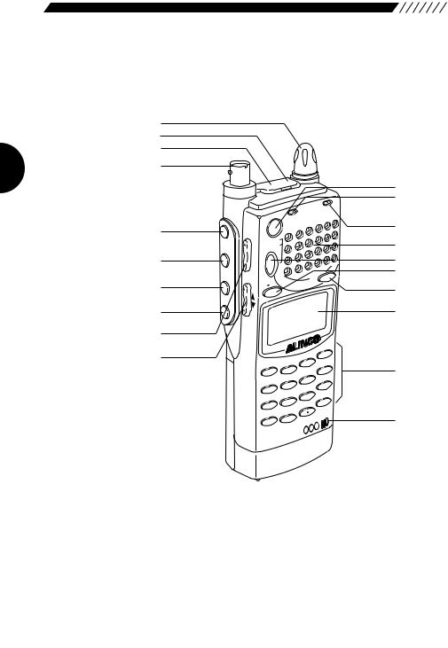
1.3 Names of parts and their functions
This section describes parts by name and function.
1.3.1 Top, front and left side panels
1.
2.
3.
4.
5.
6.
7.
8.
9.
10.
F MONI
MONI
SRCH LAMP
N
L
C
P
S
RX/ST
ER
POW
|
|
S |
|
VOL |
|
PM |
|
|
T |
|
|
|
|
SE |
|
SQL |
|
|
|
|
|
MR |
MW |
|
|
|
|
|
VFO |
|
|
UP |
A |
B |
|
|
|
||
|
|
|
|
DOWN |
|
|
|
|
|
|
|
SET |
|
|
|
|
ATT |
HELP |
|
MODE STEP |
|
E |
|||
3 |
|
||||
M NAM |
|||||
1 |
2 |
|
KL |
RF |
C |
|
AUTO |
M |
W |
-B |
S |
|
6 |
||||
MIC |
|
A |
|
||
5 |
|
S |
SCN |
||
4 |
|
||||
PRIO |
CTCS |
TF |
|
||
T |
9 |
|
|||
SCR |
8 |
|
NE |
ENT |
|
7 |
|
F TU |
|||
REC |
|
|
|
||
SKIP |
|
|
|
|
|
0 |
|
|
|
|
|
CLR |
|
|
|
|
|
|
|
|
|
MIC |
|
|
|
|
|
|
|
|
|
-X2 |
|
|
|
|
DJ |
|
|
|
|
INTELLIGENT |
|
|
|
|
|
RECEIVER |
|
|
|
|
|
11.
12.
13.
14.
15.
16.
17.
18.
19.
20.
1. Dial |
Use to switch frequency and memory channel, to |
|
|
|
adjust the audio volume and squelch level, and to |
|
|
make other settings. |
2. |
CLN terminal |
Use to clone settings between two DJ-X2000s, and |
|
|
to connect with the PC editor. |
3. |
SP terminal |
Connect an external speaker with amplifier or |
|
|
earphone here. Stereo FM radio can be received in |
|
|
stereo when stereo speakers or stereo earphones |
|
|
are connected. |
4. |
Antenna connector |
BNC connector. Attach the included antenna here. |

5. |
F (Function) key |
Use this key in combination with other keys to call up |
|
|
MONI |
specific functions. |
|
6. |
Temporarily cancels the squelch for the duration it is |
||
key |
|||
|
SRCH |
held down. Used independent of squelch level. |
|
7. |
Press to start scanning within a 40-channel range. Use |
||
key |
|||
|
|
in combination with F key to start scanning in a 7- |
|
|
LAMP |
channel range. |
|
|
Turns the key backlight ON/OFF. |
||
8. |
key |
9.VOL/SQL key Use to adjust the audio volume and squelch level.
10.UP/DOWN key Use to set frequency, to adjust the audio volume and
|
|
|
squelch level, to control various settings, and to select |
|||
|
|
|
an item in the menu display. |
|||
11. POWER switch |
Turns power ON/OFF. |
|
|
|||
12. |
Hardware reset key |
Press to reset all functions to their factory-settings. |
||||
|
|
|
However, data stored in memory is not deleted. |
|||
|
|
|
Settings might return to the settings when power was |
|||
|
|
|
turned ON the last time. |
|
||
13. Busy lamp |
Lights green when a signal is picked up and stays lit |
|||||
|
|
|
while the signal is active. Lights orange when |
|||
|
|
|
receiving FM radio in stereo (using stereo earphones). |
|||
|
|
|
In Transceiver mode, lights red while transmitting. |
|||
14. |
Speaker |
Sound is produced from here. |
||||
15. |
PMS |
key |
Shifts to the scan programming mode. If pressed in |
|||
SET |
||||||
|
|
|
combination with the |
F |
key, the scan program can |
|
|
VFO |
|
be saved in memory. |
|
|
|
|
|
|
|
|
||
16. |
A=B |
key |
Engages the dual VFO mode. If pressed in |
|||
|
|
|
combination with the |
F |
key, the frequency displayed |
|
|
MRMW |
|
in the top band is copied to the bottom band. |
|||
17. |
key |
Use to access the memory. If pressed in combination |
||||
|
||||||
|
|
|
with the F key, frequencies and other data can be |
|||
|
|
|
saved in memory. |
|
|
|
18. |
Display |
Displays frequency, operating status and other |
||||
|
|
|
information pertinent to use. |
|||
19. Key pad |
In the VFO mode, use these keys to directly input the |
|||||
|
|
|
frequency you want. Press in combination with the F |
|||
|
|
|
key to access other functions. |
|||
20. |
Built-in microphone |
Use to pick up sound and record it. |
||||
9
1.3.2 Rear and right panels
2.
1.
3.
4.
1. DC-IN |
Connect an external DC supply here (10 - 16 V). |
2. Holes for attaching belt clip
Screw the included belt clip to the DJ-X2000 here.
3.Battery case lock Slide to the right to detach the battery case.
4.EBP-37N battery pack or dry cell case
The dry cell case can hold four AA batteries.
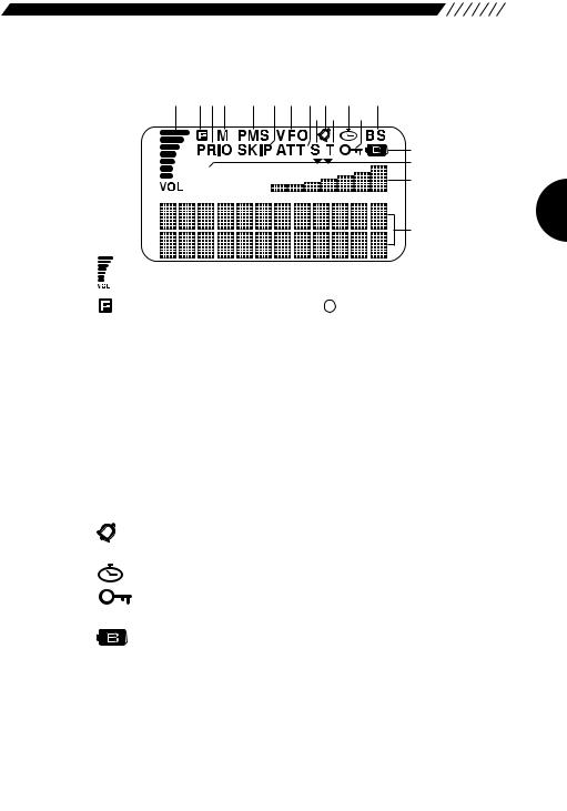
1.3.3 Display
1. |
2.3.4. |
5. |
6. 7. 8.10.12. |
14. |
|
|
|
9.11. 13. |
|
|
|
|
|
15. |
|
AM |
|
|
16. |
|
|
|
17. |
|
|
|
|
|
18. |
1. |
|
Meter for displaying sound level. |
2. |
|
Displayed when the F key has been pressed to |
|
|
indicate that you can access the subfunctions of the |
|
|
keys. |
3. |
PRIO |
Displayed while the priority function is ON. |
4. M |
Displayed in the MR mode. |
|
5. PMS |
Displayed in the PMS mode. |
|
6. |
SKIP |
Displayed for memory channels which are skipped in |
|
|
memory scans. Skip is user-set. |
7. VFO |
Displayed in the VFO mode. |
|
8. ATT |
Displayed when the attenuator is ON. |
|
9. |
S |
Displayed when a frequency indivisible by the set |
|
|
frequency step is entered. |
10. |
|
Displayed when the bell function is ON. |
11. |
T |
Displayed when the CTCSS decoder is ON. |
12. |
|
Displayed when On-timer or Off-timer is ON. |
13. |
|
Displayed while keys are locked. |
14. BS |
Displayed when the battery-save function is ON. |
|
15. |
|
Displayed when battery power is low. Promptly replace |
|
|
the batteries if this icon is displayed. |
16. AM |
Modulation mode is displayed. When the audio volume |
|
|
|
or squelch level is being adjusted, either of them is |
|
|
displayed. |
17. |
S-meter |
S-meter. Depending on settings, the time or the |
|
|
Channel Scope™ setting is also displayed here. |
18. |
Dot-matrix display This is where band, channel name and frequency are |
|
|
|
displayed in the various modes. |
11
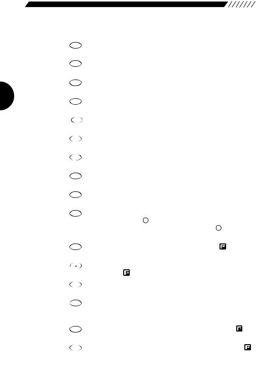
1.3.4 Key pad
MODE
1.1
STEP
2.2
ATT
3.3
Inputs 1. Press in combination with the  key to switch the modulation mode.
Inputs 2. Press in combination with the  key to set the frequency step.
Inputs 3. Press in combination with the  key to turn the attenuator ON/OFF.
MIC
4.4
AUTO MW
5.5
KL
6.6
SCRT
7.7
PRIO
8.8
CTCSS
9.9
SKIP
10.CLR
Inputs 4. Press in combination with the  key to turn the directional microphone function ON.
Inputs 5. Press in combination with the  key to turn the auto memory write function ON/OFF.
Inputs 6. Press in combination with the  key to lock/unlock keys.
Inputs 7. Press in combination with the  key to set the Descrambler.
Inputs 8. Press in combination with the  key to turn the priority function ON/OFF.
Inputs 9. Press in combination with the  key to set the CTCSS decoder.
Clears settings. In VFO mode, press in combination with the F key to set VFO-link. In PMS and MR modes, press in combination with the F key to set the scan pass frequency and skip channel.
REC
11. 0 Inputs 0. Press in combination with the key to turn the recording function ON.
12. |
F TUNE |
Inputs • (decimal point). Press in combination with the |
key to set the Flash tune function.
SET
13. HELP Press to call up the Help-navigator. Press in combination with the  key to call up menus.
M NAME
14. RFC Press to turn the RF checker ON. Press in combination with the  key to turn the Memory search function ON.
A~B S
15. SCN Starts scanning. Press in combination with the key to scan between band A and band B.
TF
16. ENT Enters input values. Press in combination with the key to turn the Transweeper ON.
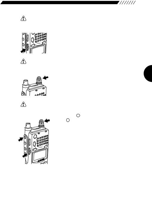
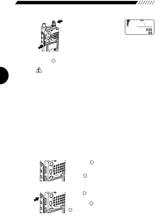
1.4 Setting up the DJ-X2000
Before using your receiver, attach the included antenna securely. If you want to use the belt clip or wrist strap, attach them too.
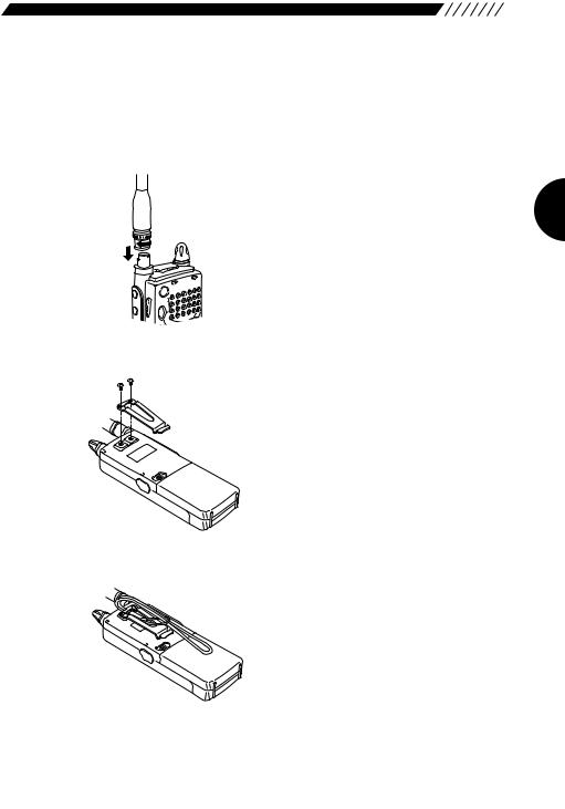
1.4.1 Attaching the antenna
Fit the base of the antenna over the projections on the connector, press downward and turn clockwise. Check to be sure the antenna is securely attached.
F MONI
MONI
SRCH
P
S
RX/ST
POWER
VOL |
PMS |
SET |
|
SQL |
MR MW |
|
|
VFO |
|
A |
B |
1.4.2 Attaching the belt clip
Screw the belt clip onto the rear panel (screws x 2). Check to be sure the clip is securely attached before use.
1.4.3 Attaching the wrist strap
Fit the wrist strap under the belt clip and pull it through its own loop.
13
1.5About the batteries
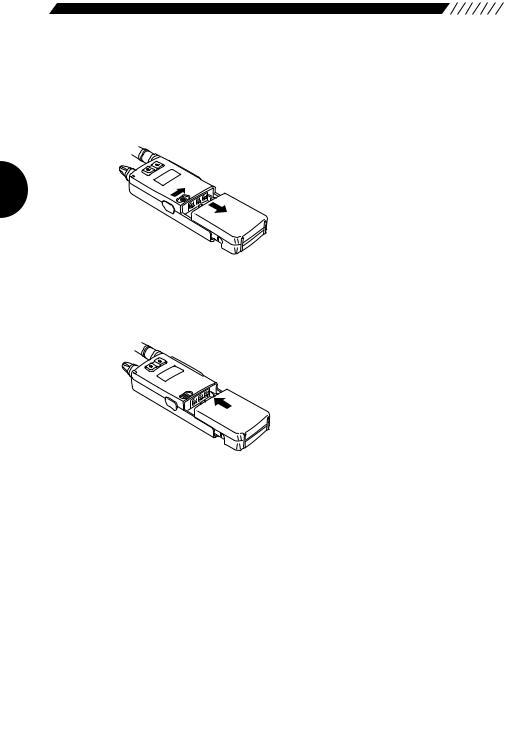
1.5.1Attaching the battery pack
• To detach the battery pack
Slide the battery pack lock on the case to the right and pull the case downward to detach.
• To attach the battery pack
Fit the battery pack into the holes on the DJ-X2000 and push in the direction of the arrow until the case snaps into the place.

1.5.2 About the battery pack
Before using the included EBP-37N battery pack, please note the following:
1.The battery pack is not charged before it is shipped from the factory. Charge the pack before using the DJ-X2000 for the first time.
2.Approximately 1 hour is required to fully charge the battery pack with the charger.
3.Charge batteries only in temperatures from 0°C to 40°C (32°F~104°F).
4.DANGER! Do not disassemble, tamper with, heat or wet the battery pack.
5.Do not short-circuit battery pack terminals. This can generate heat inside the pack resulting in burns and/or damage to the pack.
6.Do not overcharge the battery pack. Overcharging can lead to battery performance loss.
7.Store the battery pack in a cool, dry place where temperature is between -20°C and 45°C(-4°F~113°F). Environments outside this range can cause battery acid to leak and metal parts to rust.
8.The battery pack can be fully recharged approximately 300 times. When a fully charged battery pack lasts considerably less than expected, it is time to replace it with a fresh pack.
9.Do not throw away dead Ni-Cd battery packs. They can be recycled. Give them to stores which accept old batteries.
10.Do not charge an unexhausted battery pack repeatedly. It may shorten the operating time of a battery pack.
•To prevent battery pack short-circuiting
When carrying the battery pack, be extremely careful not to short-circuit the terminals. If short-circuited, the high surge in current could heat up the pack, resulting in burns or fire.
1.Keep the battery pack away from metal objects such as necklaces, etc.
2.Do not keep the battery pack inside bags with metal-plated linings or wrap it in handkerchiefs with metallic thread or print.
3.Do not leave the battery pack in proximity of electro-conductive materials or metal objects such as nails or chains.
4.Place the battery pack in an electrically-insulated bag or wrap it in a handkerchief before putting it in your handbag, etc.
5.Place the battery pack on an electrically-insulated mat when setting it on a flat surface.
15
1.5.3 Ni-Cd battery charger
The supplied battery charger (EDC-88) is designed exclusively for use with our NiCd battery pack.
 Precautions in using the charger
1.The battery charger is designed exclusively for use with our NiCd battery pack. Never use it to recharge any other rechargeable battery or dry cell.
2.Do not use the battery charger as a power source for any appliance.
3.Do not disassemble the battery charger.
4.Do not put any metal piece or wire in the battery charger, nor short-circuit the recharging terminals.
5.Do not use the battery charger in a location where the temperature rises high, e.g., near a heater or under direct sunlight, or where the dust or humidity level is high.
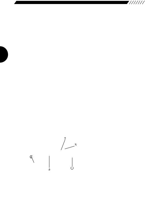
• Parts designation and function
Lamp
Indicates the status of the battery charger.
Lamp status |
Battery charger status |
Handling the battery pack |
|
|
|
Illuminated in red |
Quick recharge is in progress. |
Leave it until it has been |
|
|
recharged completely. |
Illuminated in green |
Supplemental recharge is in progress. |
It may be removed. |
|
|
|
Blinking in green |
Supplemental recharge is completed. |
Remove it. |
|
|
|
Blinking in red |
Supplemental recharge is in progress for |
Leave it until it has been |
|
the completely discharged battery pack. |
recharged completely. |
|
|
|
Blinking alternately |
An irregular battery pack is in place. |
Remove it immediately. |
in red and green |
|
|
Recharging terminals
Used for recharging the battery pack.
AC power socket
Used to plug the AC power cord.
AC power cord
Used to supply AC power.
Guides (on the right and left sides)
Used to guide the transceiver when inserting it into the battery charger.
• Recharging procedure
L |
|
|
|
1 |
AMP |
|
|
|
|
|
|
|
SET |
2 |
|
|
ATT |
HELP |
|
MODE |
STEP |
3 |
M NAME |
|
1 |
2 |
KL |
RF C |
|
MIC |
AUTO MW |
6 |
A-B S |
|
4 |
5 |
CTCSS |
SCN |
|
SCRT |
PRIO |
9 |
TF |
|
7 |
8 |
F TUNE |
ENT |
|
SKIP |
REC |
|
|
|
CLR |
0 |
|
|
|
INTELLIGENTDJ-X2 |
|
|||
RECEIVER |
|
|
|
|
|
|
|
|
3 |
Plug the AC power cord into the AC power socket on the battery charger.
Insert the battery pack being recharged, along the guides provided on both sides of the battery charger. The lamp will be illuminated in red, and quick recharge will be started.
When the quick recharge is completed, the lamp changes its color to green, indicating that supplemental recharge (*) has started.
4 About four hours after the quick recharge has started, the lamp starts blinking in green, indicating that the supplemental recharge has been completed.
Note: The supplemental recharge means recharging the battery pack with a small electric current to prevent its capacity from decreasing due to the selfdischarge. This does not overcharge the battery pack.
• Battery pack vs. recharging time
The battery packs applicable to each battery charger model and their recharging time are shown below:
Battery pack |
Battery capacity |
Recharging time |
|
|
|
|
|
EBP-33N |
4.8V |
650mAh |
Approx. 1 hour |
|
|
|
|
EBP-34N |
4.8V |
1200mAh |
Approx. 1.5 hours |
|
|
|
|
EBP-35N |
7.2V |
900mAh |
Approx. 1.2 hours |
|
|
|
|
EBP-37N |
4.8V |
700mAh |
Approx. 1 hour |
|
|
|
|
EBP-47N |
7.2V |
700mAh |
Approx. 1 hour |
|
|
|
|
17
 Precautions in recharging
1.Ensure that the transceiver is OFF when recharging the battery pack. The use of the transceiver during recharging can cause the transceiver to malfunction.
2.The battery charger is designed to be used at an ambient temperature between 10°C and 40°C (50°F and 104°F). Avoid recharging the battery pack at any temperature outside this range.
3.Do not repeatedly recharge a fully recharged battery pack. This can cause the performance of the battery pack to deteriorate. The battery pack can be recharged up to 300 times when it is used normally. If the life of the completely recharged battery pack becomes markedly shorter, the battery pack is considered to have been exhausted. Please purchase a new battery pack.
4.Do not insert the battery pack in a reverse direction.
5.When the battery pack has been recharged completely, with the lamp blinking green, remove the battery pack from the battery charger.
6.If the battery charger is not used for a long period of time, disconnect the AC power cord from the wall socket, and remove the battery pack from the battery charger.
7.If you recharge a battery pack of which voltage has abnormally dropped due to discharge, the lamp starts blinking red and a preliminary recharge initiates immediately after you have started recharging the battery pack.
Subsequently, the lamp will be illuminated red, indicating that the quick recharge has started.
8.If any irregular battery pack is set in place, the lamp will blink alternately in red and green.
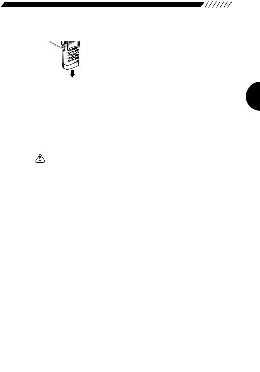
1.5.4 Battery low alarm
When batteries get low, the  icon appears on the display to the sound of a repeated siren-like alarm. Change the batteries as soon as possible.
However, the alarm is not emitted if the beep function is turned OFF.
Note: If you use the DJ-X2000 with the exhausted batteries being mounted in a state of unable to turn on the power switch. It may become unable to accept any external power. If the DJ-X2000 will not start even when you press the power switch, press the hardware reset key or detach the battery case more than 10 seconds before connecting any external power.
2. Basic operations
This chapter describes the basic operations for the DJ-X2000.
2.1 POWER switch
To turn ON/OFF the DJ-X2000, perform the following operation:
• Turning ON
RX/ST
POWER
F |
|
|
|
S |
|
MONI |
PM |
|
SET |
|
|
|
SQL |
MW |
SRCH |
VFO |
|
|
MR |
|
|
A B |
|
Hold down the POWER switch for approx. 1 second until the message “ALINCO INTELLIGENT RECEIVER™” appears on the display.
• Turning OFF
Hold down the POWER switch until the display goes out.
Note: The message that appears on the display may be changed (see “3.1.12 Changing the initial message” on page 40).
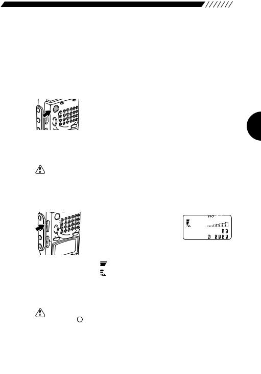
2.2 Volume control
F
 VOL
VOL
 SQL SRCH

 UP LAMP

 DOWN
DOWN
POWER
S |
|
PM |
|
SET |
|
MR |
MW |
VFO |
|
A B |
|
To turn up the volume, press the
VOL key located on the left side of the body, and then press the UP key or turn the dial clockwise. To
turn down the volume, press the
VOL key, and then press the DOWN key or turn the dial counterclockwise.
The  bars on the display will increase/decrease with
the adjacent number changed between V00 and V32 as you control the volume.
Note: To disengage the squelch (the mute function) temporarily, press and hold the MONI key on the left panel. This will enable you to set the volume setting
without changing the squelch setting (see “2.3 Squelch control” page 20).
19
2.3 Squelch control
Squelch is used to mute the speaker noise when no signal is being received. Squelch level can be selected between S00~S32. Setting is made as follows. A squelch level can be selected from the range between S00 and S32.
F MONI
MONI
LAMP
 DOWN UP SQL VOL
S |
|
PM |
|
SET |
|
MR |
MW |
VFO |
|
A B |
|
To select a squelch level, press the SQL key located on the left side of the body, and then press the UP/DOWN key or turn the dial. The squelch level will be shown on the display in accordance with the setting.
S |
5 |
A 1 4 5 . 3 4 |
|
b |
8 . |
Note: • Higher squelch levels require higher signal levels to release the muting. Set the squelch to a level at which the noise just disappears.
•The level at which to release the muting varies depending on the received frequency even if the electric field strength remains the same. Adjust the squelch at the most suitable level for the frequency to be received.
•If the squelch level is too high, weak incoming signals may not be heard from the speaker.
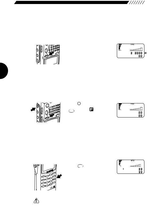
2.4Setting frequency
Frequency can be set in any of four ways: By using the numeric keys, the UP/DOWN key, the dial, or the combination of the F key and the dial.
• Setting by numeric keys
DO
MO |
DE |
STEP |
3 |
M NAME |
|||
1 |
|
2 |
|
KL |
RF |
C |
|
MIC |
|
AUTO |
MW |
6 |
A-B |
S |
|
|
|
|
|||||
4 |
|
5 |
|
CTCSS |
SCN |
||
|
PRIO |
TF |
|
||||
SCRT |
|
9 |
|
||||
|
8 |
|
F TUNE |
ENT |
|||
7 |
|
|
|||||
|
REC |
|
|
|
|||
SKIP |
|
|
|
|
|
||
|
0 |
|
|
|
|
||
CLR |
|
|
|
|
|
||
|
|
|
|
|
MIC |
||
|
LLIG |
ENT |
-X2 |
|
|
||
|
DJ |
|
|
|
|||
INTE |
EIVER |
|
|
|
|
||
REC |
|
|
|
|
|
|
|
Input the frequency directly from the numeric keys and then press
TF
the ENT key.
NFM |
|
|
|
A |
1 4 5 . |
3 4 |
|
b |
|
8 . |
|
|
|
|
|
|
MODE |
MIC |
AUTO MW |
F TUNE |
Example 1 To set 145.3400 MHz, press the 1 , |
4 , |
5 , |
, |
|||||
ATT |
, |
MIC |
, and |
TF |
keys in the given order. |
|
||
3 |
|
4 |
|
ENT |
|
|
|
|
The 00 on the end can be omitted.
Example 2 To set 0.5580 MHz (that is, 558 kHz), press the |
REC |
F TUNE |
||||||||
0 |
, |
|||||||||
|
|
|
|
PRIO |
|
|
|
|
, |
|
AUTO MW |
, |
AUTO MW |
, |
, |
and |
TF |
keys in the given order. |
|||
5 |
5 |
8 |
ENT |
|||||||
|
|
|
|
|
|
|
|
|||
The 0 on the end can be omitted.
Note: If you enter any frequency that cannot be divided by the set frequency step, “S” appears on the display.
• Setting with the UP/DOWN key
F MONI
MONI
SRCH
UP SQL VOL
S |
|
PM |
|
SET |
|
MR |
MW |
VFO |
|
A B |
|
For higher frequencies, press the UP key. For lower frequencies, press the DOWN key. The frequency will increase/decrease in the set frequency steps.
LAMP
DOWN
Note: For changing the frequency step, see “3.1.2 Setting the frequency step” (page 32).
• Setting from the dial
N
L
C
P
S
For higher frequencies, turn the dial clockwise. For lower frequencies, turn it counterclockwise. The frequency will increase/decrease in the set frequency steps.
F
RX/ST  POWER
POWER 
Note: For changing the frequency step, see “3.1.2 Setting the frequency step” (page 32).
• Setting with the combination of the F key and the dial
F MONI
MONI
SRCH LAMP
N
L
C
P
S
RX/ST
POWER
|
|
S |
|
VOL |
|
PM |
|
|
SET |
|
|
SQL |
|
|
MW |
|
|
MR |
|
|
VFO |
|
|
UP |
A |
B |
|
|
|
|
|
DOWN |
|
|
|
|
ET |
EP |
HELP |
E |
Press the F key, and then press the UP/DOWN key while  is shown on the display. An under-bar will appear at the digit of 100, 10, or 1 MHz. Now turning the dial allows
you to change the number at that digit. Pressing the UP/DOWN key shifts the digit at which the number can be changed.
21
2.5 Switching frequency band
The DJ-X2000 uses a dual VFO system, so that a frequency change can be done smoothly by inputting a new frequency on the second band in advance. The frequency currently being monitored is displayed next to the capital letter on the top line of the display. Frequency band can be switched as follows.
MONI
SRCH LAMP
 DOWN UP SQL VOL
PMS  SET
SET 
VFO
A B
MW
Press the  key. The frequencies on the top and bottom lines will switch places, with the letters changing between capital and lower case.
NFM |
|
|
B |
8 . |
|
a 1 4 5 . |
3 4 |
|
2.6 Copying frequencies from one band to the other
The frequency on the currently used band can be copied into the other band as follows.
F MONI
MONI
SRCH LAMP
N UP SQL VOL
POWER
PMS 
SET
MW
VFO
A B
Press the F key, and then press
VFO |
key while |
is shown on |
NFM |
the A=B |
the display. |
A 1 4 5 . 3 4 |
|
b 1 4 5 . 3 4 |
||
This will copy the frequency on the |
||
|
currently used band (displayed on top line next to capital letter) into the other band (displayed on bottom line next to small case letter).
2.7 Scanning
Scanning is used to locate frequencies with signals present. Basic scanning operations are as follows.
• To scan
DOWN
|
|
|
|
|
ET |
|
|
|
|
|
|
HELP |
|
MO |
DE |
STEP |
3 |
|
|
|
M NAME |
||||||
1 |
2 |
|
KL |
RF |
C |
|
MIC |
AUTO |
MW |
6 |
A-B |
S |
|
|
|
|||||
4 |
5 |
|
CTCSS |
SCN |
||
PRIO |
TF |
|
||||
SCRT |
9 |
|
||||
8 |
|
F TUNE |
ENT |
|||
7 |
|
|||||
REC |
|
|
|
|||
SKIP |
|
|
|
|
||
0 |
|
|
|
|
||
CLR |
|
|
|
|
||
|
|
|
|
MIC |
||
TELLIG |
ENT |
-X2 |
|
|
||
ERDJ |
|
|
|
|||
A~B S |
NFM |
|
Press the SCN key. Scanning will |
|
|
|
||
start and will proceed in the set |
A 1 4 5 . 3 4 |
|
frequency steps. |
b 1 4 5 . 3 4 |
|
|
|
While scanning, an arrow icon is displayed next to the frequency on currently used band (displayed on top line next to capital letter). The arrow points to the left while scanning towards the higher frequencies.
Note: If CTCSS or A/B Squelch is selected, the scan may be delayed since it takes
some time to match the selected parameters.
If live frequencies are received, scanning is temporarily stopped. To resume scanning, turn the dial or press the UP/DOWN key. Scanning can be automatically resumed by specifying scan resuming conditions. For further details, see “3.1.15 Setting scan resume condition (SCAN MODE)” (page 42).
• To switch scanning direction
While scanning, press the DOWN key. The arrow icon will face right and scanning will proceed toward the lower frequencies. To scan toward the higher frequencies, press the UP key. The scanning direction can also be changed by turning the dial.
• To cancel scanning
A~B S
Press the SCN key again.
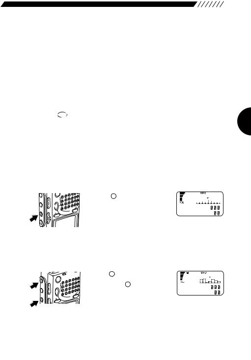
2.8 Searching (Channel Scope™)
The search function, or Channel Scope of the DJ-X2000 checks frequencies in the set frequency steps, and displays signals within a 40-channel or 7-channel range at one time. The function is useful for checking the spectrum occupancy at a glance. It is used as follows.
• 40-channel search
F |
|
|
|
|
|
S |
|
MONI |
VOL |
PM |
|
SET |
|
||
|
SQL |
|
MW |
SRCH |
|
VFO |
|
|
|
MR |
|
|
UP |
A B |
|
LAMP |
|
|
|
DOWN |
|
|
|
|
|
|
Press the SRCH key on the left side panel. The DJ-X2000 will start searching for signals within a 40-
channel range of the currently
received frequency. The search proceeds in set frequency steps with the displayed frequency in the center under ▼ mark. The higher channel spectra are displayed towards the right, and the lower to the left. Vertical length of each spectrum indicates relative strength of the signals.
• 7-channel search
RX/ST
POWER
F |
|
|
|
|
|
S |
|
MONI |
VOL |
PM |
|
SET |
|
||
|
SQL |
|
MW |
SRCH |
|
VFO |
|
|
|
MR |
|
|
UP |
A B |
|
L |
|
|
|
|
|
|
Press the F key to display  Then, press the SRCH key on the left side panel. The DJ-X2000 will start
searching for signals within a 7-
channel range of the currently received frequency. The search proceeds in the set frequency steps with the displayed frequency in the center under ▼ mark. The higher channel spectra are displayed towards the right, and the lower to the left. Vertical length of each spectrum indicates strength of the signals.
23
• To tune in live frequencies
F
MONI
SRCH
UP SQL VOL
RX/ST
POWER
PMS 
SET

 MR MW
MR MW
VFO
A B
To move live frequencies to the left, turn the dial clockwise or press the UP key. To move them to the right, turn the dial counterclockwise or press the DOWN key.
WFM |
|
|
A |
8 1 |
. 5 |
b |
1 4 5 |
. 3 4 |
LAMP
DOWN

 SET • To cancel the search
Press the SRCH key again. This will cancel the search.
Note: • For specifying search resuming conditions, see “3.1.22 Setting search resume condition (SRCH MODE)” (page 48).
•The search resume condition factory-setting is INTERVAL. Sound is muted during the search. The search operation is performed every 10 seconds.
•It may be difficult to read a value from the S meter during scanning in the Channel Scope mode, because the speed is fast.
•The graph displayed in the Channel Scope mode is only in the range of the currently received radio type. For example, if search is performed around 76.5 MHz of WFM, no channel less than 76.0 MHz, which is NFM, is displayed.
•If the Channel Scope mode is selected, the battery saving function is disabled.
•If the search function is turned ON in the MR mode, it may take some time for a full display of the search.
•If scanning is started with the search function turned ON, it may take some time to start scanning.
2.9Monitoring (Squelch OFF)
The monitor function is used to pick up weak signals .
• To turn the monitor ON
F MONI
MONI
 SRCH LAMP
UP SQL VOL
R
POWER
S |
|
PM |
|
SET |
|
MR |
MW |
VFO |
|
A B |
|
Hold down the MONI key. While the key is depressed, the squelch is turned OFF and weak signals can be picked
up. (Noise is heard if no signal is being received.) When the MONI key is released, the squelch comes back
ON and the DJ-X2000 returns to its original state.
• To keep the monitor ON at all times
MONI
F MONI
MONI
 SRCH LAMP
UP SQL VOL
R
POWER
S |
|
PM |
|
SET |
|
MR |
MW |
VFO |
|
A B |
|
Press the F key, and then press the  key while
  is shown on the display. The squelch will remain OFF
even after the |
MONI |
key has been released. Pressing the |
MONI key a second time will reactivate the squelch.
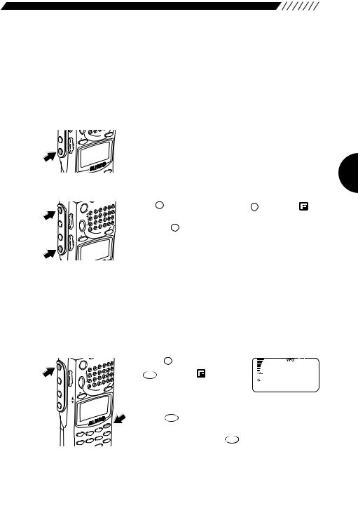
2.10 Turning backlight ON/OFF
The DJ-X2000 has a backlight to make it easier to use at night. The backlight can be turned ON/OFF as follows.
2.10.1Turning backlight ON/OFF manually
• To turn the backlight ON
LAMP
SRCH

 UP LAMP
 DOWN
DOWN
MR |
MW |
VFO
A B
ET
HELP
Press the  key. The display will be lit while operating the dial or keys. Keys also light up when pressed or held down. The backlight goes OFF automatically if the controls are not used for approximately 5 seconds.
• To leave the backlight ON at all times
F MONI
MONI
SRCH
UP SQL VOL
POWER
S |
|
PM |
|
SET |
|
MR |
MW |
VFO |
|
A B |
|
Press the F key, and then press the LAMP key while
is shown on the display. The backlight will remain ON until you press the LAMP key again.
LAMP
DOWN
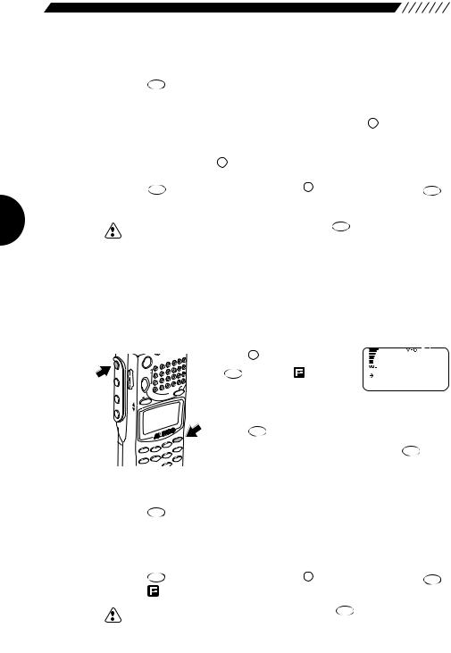
2.10.2Turning backlight ON/OFF based on the setting
The backlight can be automatically turned ON/OFF in accordance with the setting. To do so, perform the following steps:
1 Call up the LAMP screen.
F MONI
MONI
SRCH LAMP
 DOWN UP SQL VOL
POWER
S |
|
PM |
|
SET |
|
MR |
MW |
VFO |
|
A B |
|
|
|
|
|
|
SET |
|
|
|
|
|
ATT |
HELP |
|
MO |
DE |
STEP |
3 |
|
|
|
M NAME |
||||||
1 |
2 |
|
KL |
RF |
C |
|
MIC |
AUTO |
MW |
6 |
A-B |
S |
|
|
|
|||||
4 |
5 |
|
CTCSS |
SCN |
||
PRIO |
TF |
|
||||
|
|
9 |
|
|||
Press the |
F key, and then press |
|
|
the HELPSET |
key while |
is shown |
LAMP |
on the display. The MENU will |
M O M E N T A R Y |
|
A L T E R N A T E |
||
appear. Point the arrow at |
||
|
+CONFIG using the dial or UP/DOWN key, and then
TF
press the ENT key.
The CONFIG menu will appear. Point the arrow at
TF
+LAMP, and then press the ENT key. The LANP screen will appear.
25
2 Select a backlight mode as follows:
Using the dial or UP/DOWN key, point the arrow at a desired mode, and then
TF |
|
|
|
press the ENT key (the initial setting is the MOMENTARY mode). |
|
||
AUTO: |
The backlight is lit for 5 seconds after the dial or key is |
||
|
used. |
LAMP |
|
|
|
key is being |
|
MOMENTARY: The backlight remains lit only while the |
|||
|
held down. |
|
|
ALTERNATE: |
The backlight is turned alternately ON and OFF every time |
||
|
LAMP |
key is pressed. |
|
|
the |
|
|
The display will go back to the CONFIG menu. Point the arrow at END, and then
press the |
TF |
key (or alternatively, press the F key, and then press the |
TF |
ENT |
ENT |
key with  shown on the display.
Note: If you exit the CONFIG menu by pressing the setting is canceled.
SKIP
CLR key, the changed
2.11 Turning beep ON/OFF
The beep sound that is emitted when a key is pressed or a specific operation is performed can be turned ON/OFF and its volume can be controlled as follows:
1 Call up the BEEP screen.
F MONI
MONI
SRCH LAMP
 DOWN UP SQL VOL
POWER
S |
|
PM |
|
SET |
|
MR |
MW |
VFO |
|
A B |
|
|
|
|
|
|
ET |
|
|
|
|
|
|
HELP |
|
MO |
DE |
STEP |
3 |
|
|
|
M NAME |
||||||
1 |
2 |
|
KL |
RF |
C |
|
|
MW |
S |
||||
MIC |
AUTO |
6 |
A-B |
|||
4 |
5 |
|
CTCSS |
SCN |
||
PRIO |
TF |
|
||||
|
|
|
|
|||
Press the |
F key, and then press |
BEEP |
|
|
|
the HELPSET |
key while |
is shown |
|
|
|
on the display. The MENU will |
H i g h |
|
|
||
L OW |
|
|
|||
appear. Point the arrow at |
|
|
|
||
+CONFIG using the dial or UP/DOWN key, and then |
|||||
press the |
TF |
|
|
|
|
ENT key. The CONFIG menu will appear. |
|||||
Point the arrow at +BEEP, and then press the |
TF |
key. |
|||
|
|||||
ENT
The BEEP screen will appear.
2 Select a beep sound mode.
Using the dial or the UP/DOWN key, point the arrow at a desired mode, and then
TF |
key (the initial setting is the HIGH mode). |
press the ENT |
|
OFF: |
The beep sound is turned OFF. |
HIGH: |
The beep sound is emitted at a high level. |
LOW: |
The beep sound is emitted at a low level. |
The display will go back to the CONFIG menu. Point the arrow at END, and then
|
TF |
|
TF |
|
press the |
ENT key (or alternatively, press the |
F key, and then press the |
||
ENT |
||||
key while |
is shown on the display.). |
|
|
|
|
|
SKIP |
|
|
Note: |
•If you exit the CONFIG menu by pressing the CLR key, the changed |
|
||
setting is canceled.
•If stereo earphones are used, the beep sound can be heard from the left earphone only.
 Loading...