


 Loading...
VHF/UHF FM TRANSCEIVER
DR-635T/E
Instruction Manual
Thank you for purchasing your new Alinco transceiver.
This instruction manual contains important safety and operating instructions. Please read this manual carefully before using the product and keep it for future reference.

NOTICE / Compliance Information Statement
This equipment has been tested and found to comply with the limits for a Class B digital device, pursuant to part 15 of the FCC Rules.
These limits are designed to provide reasonable protection against harmful interference in a residential installation. This equipment generates, uses, and can radiate radio frequency energy and, if not installed and used in accordance with the instruction manual, may cause harmful interference to radio communications. However, there is no guarantee that interference will not occur in a particular installation. If this equipment does cause harmful interference to radio or television reception, which can be determined by turning the equipment off and on, the user is encouraged to try to correct the interference by one or more of the following measures:
•Reorient or relocate the receiving antenna.
•Increase the separation between the equipment and receiver.
•Connect the equipment into an outlet on a circuit different from that to which the receiver is connected.
•Consult the dealer or an experienced radio/TV technician for help.
Tested to Comply
With FCC Standards
FOR HOME OR OFFICE USE
Information in this document is subject to change without notice or obligation. All brand names and trademarks are the property of their respective owners. Alinco cannot be liable for pictorial or typographical inaccuracies. Some parts, options and/or accessories are unavailable in certain areas. Changes or modifications not expressly approved by the party responsible for compliance could void the user's authority to operate the equipment.
VHF/UHF FM Transceiver DR-635T
This device complies with Part 15 of the FCC Rules. Operation is subject to the following two conditions: (1) This device may not cause harmful interference, and (2) this device must accept any interference received, including interference that may cause undesired operation.
Manufacturer:ALINCO,INC
Shin-Dai building 9th Floor 2-6, 1-Chome, Dojimahana, Kita-ku, Osaka 530-0004, JAPAN
Conformity Information
In case the unit you have purchased is marked with a CE symbol, a copy of relative conformity certificate or document can be reviewed at http://www.alinco.com/usa.html. Please see the back-cover for more details.
Copyright © 2005 All rights reserved. No part of this document may be reproduced, copied, translated or transcribed in any form or by any means without the prior written permission of Alinco. Inc., Osaka, Japan. English Edition Printed in Japan.

Contents
Before operating the transceiver ............. |
3 |
Attention ................................................................ |
3 |
Introduction ............................................... |
3 |
New and Innovative Features ................... |
4 |
Standard Accessories .............................. |
5 |
Initial Installation ....................................... |
6 |
For a base station set up ....................................... |
6 |
For a mobile station set up .................................... |
7 |
Location .................................................... |
7 |
Installing a Mobile Antenna ....................... |
7 |
Installing the Transceiver .......................... |
7 |
Front Panel ............................................................ |
8 |
External power control function ............................. |
9 |
Power supply voltage display function ................. |
10 |
Part Names and Functions ..................... |
11 |
Front Panel ........................................................... |
11 |
Rear Panel ........................................................... |
12 |
Display ................................................................. |
13 |
Microphone EMS-53 (Standard) .......................... |
14 |
Basic Operations ..................................... |
15 |
Turning the unit on and off ................................... |
15 |
Switching the MAIN band .................................... |
15 |
Audio Volume level setting .................................. |
15 |
Squelch level setting ............................................ |
15 |
Squelch level setting on the SUB band .. |
15 |
VFO mode ........................................................... |
16 |
Changing frequency by channel step ...... |
16 |
Changing frequency by 1 MHz step ........ |
16 |
Setting the channel step ...................................... |
17 |
Shift Direction and Offset frequency setting ........ |
18 |
Memory Mode ...................................................... |
19 |
Recalling a memory channel ................... |
19 |
How to program memory channel (s) ...... |
20 |
Memory channel deleting .................................... |
21 |
Programmable data in the memory channel ... |
21 |
Channel name (Alphanumeric) registration function ..... |
22 |
CALL mode .......................................................... |
23 |
To recall a CALL channel ..................................... |
23 |
To receive signals ................................................ |
23 |
Monitor function ................................................... |
24 |
Reverse function .................................................. |
24 |
To transmit ........................................................... |
25 |
Selecting transmission power ................. |
25 |
Parameter Setting Mode ......................... |
26 |
A list of the parameters ........................................ |
26 |
To use the parameter setting mode ..................... |
27 |
Channel Step setting ........................................... |
28 |
Scan Type ............................................................ |
28 |
Beep Sound ......................................................... |
28 |
Time-Out-Timer (TOT) ......................................... |
29 |
TOT Penalty ......................................................... |
29 |
Setting the TOT penalty time .................. |
29 |
APO-Auto Power OFF ......................................... |
30 |
Tone-Burst Frequency ......................................... |
30 |
Clock shift ............................................................ |
30 |
Bell ....................................................................... |
31 |
Busy-Channel-Lock-Out (BCLO) ......................... |
31 |
Theft Alarm .......................................................... |
31 |
TX display color ................................................... |
32 |
RX display color ................................................... |
32 |
Stand-by display color ......................................... |
32 |
Dimmer ................................................................ |
33 |
Call sign setting (In packet operation) ................. |
33 |
Transmission speed setting (In packet operation) ... |
34 |
Beacon interval setting |
|
(In geolocating communication/A.P.R.S) ............. |
34 |
Useful functions ...................................... |
35 |
Reception band switching .................................... |
35 |
V-V/U-U simultaneous reception ......................... |
35 |
Single-band mode ............................................... |
36 |
VFO Auto-program setting function ..................... |
36 |
SCANNING FUNCTION ...................................... |
37 |
•VFO Scan .............................................. |
37 |
•Memory Scan ........................................ |
38 |
•Skip-channel setting .............................. |
38 |
•Program Scan ........................................ |
39 |
•Tone Scan .............................................. |
39 |
•DCS scan .............................................. |
40 |
KEY-LOCK FUNCTION ....................................... |
40 |
TONE BURST ...................................................... |
40 |
1

Contents
Narrow-band mode .............................................. |
41 |
AM receiver mode ............................................... |
41 |
Selective Communication ...................... |
42 |
Tone-squelch (CTCSS) and DCS ........................ |
42 |
DET setting ............................................. |
43 |
Digital voice communication (DR-635T only) .. |
44 |
Special Functions ................................... |
45 |
THEFT ALARM .................................................... |
45 |
To connect, set and operate ................... |
45 |
How the alarm operates .......................... |
46 |
Setting alarm starting time ...................... |
47 |
Cable Clone ......................................................... |
48 |
Connection .............................................. |
48 |
Setting on the Slave side ........................ |
48 |
Setting on the Master side ...................... |
49 |
Packet Communication ........................................ |
50 |
When using EJ-50U ................................ |
50 |
Packet Mode Setting ............................... |
51 |
APRS ................................................................... |
52 |
APRS Settings ........................................ |
52 |
APRS operation ...................................... |
53 |
TNC Clone .............................................. |
54 |
Remote Control Operation (EMS-57 only) ........... |
55 |
List of Remote Control Keys ................... |
55 |
Entering a frequency directly .................. |
56 |
Entry method depending on tuning step ... |
56 |
Maintenance / Reference ........................ |
57 |
Reset ................................................................... |
57 |
Factory Default Settings .......................... |
57 |
Troubleshooting ................................................... |
58 |
Optional accessories ........................................... |
59 |
Transmitter Block Diagram .................................. |
60 |
Specification ........................................................ |
61 |
2

Before operating the transceiver
Attention
•Do not remove the case or touch the interior components. Tampering can cause equipment trouble.
•Do not use or keep the transceiver where it is exposed to direct sunlight, dusty places, or near sources of heat.
•Keep the transceiver away from TV's or other equipment when it interferes with reception.
• When transmitting for long periods of time at high power, the transceiver might overheat.
• Turn the power off immediately if the transceiver emits smoke or strange odors. Ensure the transceiver is safe, then bring it to the nearest Alinco service center.
Notice to California resident users
The Safe Drinking Water and Toxic Enforcement Act of 1986 of the State of California determines that lead and cadmium (used as raw materials in some of the components in this product) are considered carcinogens and reproductive toxicants. Although in the normal use of our products the risk of direct contact with such materials at hazardous level is minimal, please be advised that:
(1)You should wash your hands after having contact with PVC (polyvinyl chloride) coated materials such as DC cables. PVC may contain lead or lead compounds.
(2)Wash your hands after having contact with soldered parts. Solder used for the assembly of our products may contain lead or lead compounds.
(3)Do not directly touch any liquid that may leak from the Nickel Cadmium rechargeable cells. The liquid may contain cadmium.
(4)Avoid oral contact with any part of our products. If this should occur, rinse the mouth with plenty of water. Consult a doctor if you are unsure if the exposure may have reached hazardous levels.
(5)Keep our products away from the reach of children. Our products may contain small parts that may cause suffocation, or other consequences, if swallowed.
(6)Our products are designed for two-way communication purposes only. Any eventual consequences arising from hazardous contacts with defined material(s) caused by misuse of our products are considered to be the user's fault. Please read the instruction manual of this product carefully before use.
(7)Please dispose of or recycle our products properly in accord with your local regulation(s).
(8)The user assumes the risk for exposure to chemicals/materials at hazardous levels caused by the use of peripherals or accessories made by third-parties and used in conjunction with our products.
Introduction
Thank you very much for purchasing this excellent Alinco transceiver. Our products are ranked among the finest in the world. This radio has been manufactured with state of the art technology and it has been tested carefully at our factory. It is designed to operate to your satisfaction for many years under normal use.
PLEASE READ THIS MANUAL COMPLETELY TO LEARN ALL THE FUNCTIONS THE PRODUCT OFFERS. WE MADE EVERY ATTEMPT TO WRITE THIS MANUAL TO BE AS COMPREHENSIVE AND EASY TO UNDERSTAND AS POSSIBLE. IT IS IMPORTANT TO NOTE THAT SOME OF THE OPERATIONS MAY BE EXPLAINED IN RELATION TO INFORMATION IN PREVIOUS CHAPTERS. BY READING JUST ONE PART OF THE MANUAL, YOU RISK NOT UNDERSTANDING THE COMPLETE EXPLANATION OF THE FUNCTION.
3

New and Innovative Features
Your new radio features some of the most advanced functions and reliable engineering available anywhere. The ALINCO design philosophy is focused on developing innovative usable features, including the following:
•Full-duplex operation and Cross-band repeat function*.
•A large, color-selectable display panel
Very clear display of frequency, memory name etc. ensure convenient operation.
•Excellent frequency stability
By using a temperature compensated crystal oscillator (TCXO), deviation less than +/- 2.5ppm is realized.
•V-V/U-U function
Simultaneous reception of 2 signals within the same band is possible (Excluding the
FM broadcast band).
•High-quality materials are used throughout the product and a huge heat sink around the chassis ensures stable and durable operation.
•AM Air-band reception capability (T models only)
•200 fully programmable memory channels with alphanumeric memory channel labels
•CTCSS, DCS and 5 different Tone-Bursts are standard for selective calling and repeater access worldwide.
•Applicable for Packet communication (With the optional EJ-50U installed)
•Theft Alarm feature
•Auto-Programming VFO for easier repeater access
•Cable-Clone function
•Power supply voltage display function
•Narrow-FM mode
•Microphone remote control function (EMS-57 microphone may be an option depending upon the version you purchased.)
•Front-Control unit separation
*Wherepermitted.
4

Standard Accessories
Carefully unpack to make sure the following items are found in the package in addition to this manual:
• Transceiver |
• Microphone EMS-53 or EMS-57 (with |
|
DTMF keypad) |
•DC power cable with fuse holder (UA0038) |
• Mobile mounting bracket. (FM0078Z) |
||||||
|
|
|
|
|
|
|
|
|
|
|
|
|
|
|
|
•ACC cable (UX1290A) |
• Hardware kit for bracket |
|
|
Black screws (M4*8mm) |
Tapping screws |
|
4pcs. (AE0012) |
(M5*20mm) 4pcs. (AJ0003) |
•Theft Alarm stickers 2pcs. (PR0454) •Instruction manual (this manual)
•Warranty certificate (T version only) (PH0009A)
• EJ-50U manual & disc (with TNC version only)
Screws (M5*20mm) |
Washer (AZ0010) |
4pcs. (AA0013) |
S-washer (AZ0009) |
Hexagonal nut (M5) 4pcs. |
Small (spanner) wrench. |
(AN0002) |
(FM0079) |
Spare fuses (a pair) |
|
2pcs. (EF0005) |
|
The standard accessories may vary slightly depending on the version you have purchased. Please contact your local authorized Alinco dealer should you have any questions. ALINCO and authorized dealers are not responsible for any typographical errors there may be in this manual. Standard accessories may change without notice.
Warranty Policy:
Please refer to any enclosed warranty information or contact your authorized Alinco dealer / distributor for the warranty policy.
5
Initial Installation
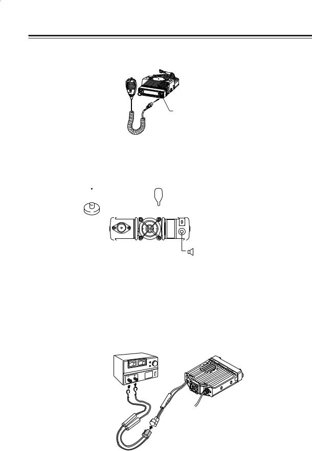
Connect the microphone to the front panel of the transceiver.
Microphone connector
Connect antenna port to a 50 ohm antenna that covers the 2 m/70 cm bands, using good quality 50 ohm coaxial cable.
Antenna |
Microphone |
|
||||||
|
|
|
|
|
|
|
|
|
|
|
|
|
|
|
|
|
|
|
|
|
|
|
|
|
|
|
|
|
|
|
|
|
|
|
|
|
|
|
|
|
|
|
|
|
|
|
|
|
|
|
|
|
|
|
|
|
|
|
|
|
|
|
|
|
|
|
|
|
|
|
|
|
|
|
|
|
|
|
|
|
|
|
|
|
|
|
|
|
|
rear panel |
External speaker |
(if used)
For a base station set up
The Transceiver requires a 12-13.8VDC negative grounded power source.
Use a regulated power supply capable of providing continuous current of 12A or more.
Power supplies that do not meet those specifications may cause malfunction and/or damage to the radio and will void the warranty. Alinco offers excellent communication-grade power supplies as optional accessories. Please contact your local authorized Alinco dealer.
DC
power supply
Red lead
Black lead
DC power cable
6
Initial Installation
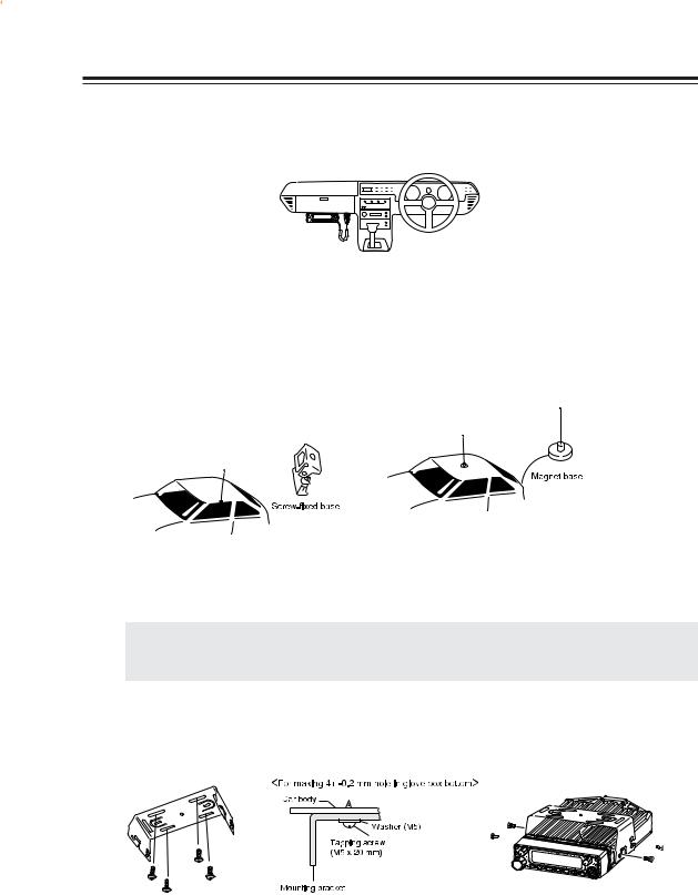
For a mobile station set up
Location
The transceiver may be installed in any position in your car, where the controls and microphone are easily accessible and it does not interfere with the safe operation of the vehicle or the performance of the set. If your vehicle is equipped with air bags, be certain your radio will not interfere with their deployment. If you are uncertain about where to mount the unit, contact your vehicle's manufacturer. Please refer the next page for positioning the front control unit.
Installing a Mobile Antenna
Use a 50 ohm coaxial cable to connect the antenna. Mobile antennas require an appropriate mounting base for proper installation and operation. For more information, see the documentation for your antenna.
IMPORTANT: After installing your antenna, ensure that you have the best possible SWR reading. High RF environments can cause severe damage to your unit. Ensure that you are not in a high RF environment when operating the transceiver.
Installing the Transceiver
See the figures below.
b


 b a
b a 


a
*Use provided screws only(M4 x 8mm) to fix the bracket. Irregular screws may damage the circuit-board inside.
7

Initial Installation
Front Panel
The main unit can be set with either side facing up. This can facilitate your ability to hear the speaker clearly. Position the front panel as you prefer.
1. Slide the front panel while keeping the tab pressed.
 Main unit
Front panel
Tab
2. Turn the front panel, being careful to keep the cable free from kinks.
3. Match the catch in the main unit with the slot in the front panel and fit the front panel into the main unit.
Catch
Slot
4. Slide the front panel until it locks securily in place.
NOTE: By using the optional separation kit EDS-9, you can use the front panel and the main unit in separate positions. The instruction manual for remote placement is provided with the EDS-9.
8
Initial Installation
External power control function
When installing, be sure the tube is placed in the slot.
Red: For connection with the ACC power supply Black: For connection with the ground(-) wire
Black
Red  CN11
CN11
ON
SW11
ACC
ACC external power supply control function is on
WARNING: The connection of cables may involve certain knowledge about the vehicle into which the unit will be installed. Consult with your car-dealer or service station for more information if necessary, as we are not responsible for any damage this installation might cause to your vehicle.
1. Be sure the vehicle has a negative-ground, 12VDC electric system before installation. Connect the provided DC cable with fuse-holder directly to the battery (red cable to the positive terminal) to minimize any possible ignition noise. Be sure the vehicle has a large capacity battery as the use of a transceiver may overload the electric system of the vehicle.
2. In addition, if the optional ignition-key ON/OFF feature is desired, use the provided ACC cable. Remove the cover by unscrewing 4 screws. Connect the ACC cable to the ACC power jack (CN11) on the rear side of the circuit board unit, position the outgoing cable as shown above, select the ACC switch (SW11) to ACC position and reassemble the cover.
3. When installing, be sure to disconnect the battery cables of the vehicle and be sure the ignition key is in the “OFF” position. Connect the ACC cable to the ACC terminal or ACC switch on the vehicle. Make sure the above sequence has been done properly. Reconnect the vehicle’s electric system.
4. If this option is selected, the unit can be turned on/off either manually or automatically in accordance with the ignition key position.
A:When the ignition key is turned to ACC or ON (“run”) position with the unit left turned ON, the unit will turn on automatically and turns OFF when the ignition key is turned to the OFF position.
B:To manually turn the power on/off, leave the ignition key in the ACC position and use the PWR switch on the unit. If the ignition key is in the OFF position the unit won't turn on. The power consumption of this feature is about 5mA regardless of the ignition key position. For operation without this option, always use the PWR switch to turn the unit on/off and set SW11 to “on”.
9

Initial Installation
Power supply voltage display function
After connecting the transceiver to a power supply, the supply voltage can be confirmed by pressing the SQL key together with the FUNC key. The supply voltage to the transceiver is then seen on the display.
The transceiver will return to its normal display when any key is pressed.
The display immediately changes as the voltage supply changes.
It also displays voltage during transmission.
(Example) In case of 13.6V
IMPORTANT: The range of the displayed voltage is only from 7 - 16VDC. Because the displayed value is estimated, please use a voltmeter when a more precise reading is desired.
10
Part Names and Functions
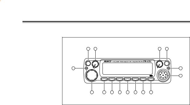
Front Panel
|
6 |
2 |
|
|
|
|
|
3 |
1 |
|
|
MW |
|
|
|
|
|
|
|
|
|
|
V/M |
|
|
|
|
|
|
|
PWR |
|
4 |
MAIN |
MAIN |
|
|
|
|
|
SUB |
SUB |
5 |
TX/RX |
|
|
|
|
|
RX |
||||
|
|
VOL |
|
|
|
|
|
VOL |
|
|
|
|
VV/UU |
RX BAND |
SHIFT |
LOCK |
PACKET |
DIGITAL |
SET |
|
15 |
|
|
BAND |
CALL |
MHz |
TS/DCS |
H/L |
SQL |
FUNC |
|
|
|
7 |
8 |
9 |
10 |
11 |
12 |
13 |
14 |
|
|
•Primary Functions
No. |
Key |
Function |
1 |
PWR key |
Power turns ON/OFF whenever switch is pressed. |
2 |
Main VOL knob |
Adjusts the volume level on the MAIN band. |
3 |
Sub VOL knob |
Adjusts the volume level on the SUB band. |
4 |
Main TX/RX |
During transmission on the MAIN band, illuminates in |
|
indicator |
Red, and during reception illuminates in Green. |
5 |
Sub RX lamp |
During reception on the SUB, illuminates in Green. |
6 |
V/M/MW |
Switches between VFO mode and memory mode. |
7 |
Dial |
Changes the frequency, memory channel and various settings. |
8 |
BAND/VVUU |
Switches the MAIN band to VHF or UHF. |
9 |
CALL/RX BAND |
Switches to CALL Mode. |
10 |
MHZ/SHIFT |
In VFO mode, changes frequency in 1 MHz steps. |
11 |
TSDCS/LOCK |
Sets the tone squelch and DCS setting. |
12 |
HL/ PACKET |
Switches HI/MID/LOW of transmission power. |
13 |
SQL/DIGITAL |
Sets the squelch level. |
14 |
FUNC/SET |
Sets functions. |
15 |
Mic. Connector |
Connection for the provided microphone. |
• Functions which can be activated while [F] appears, after pressing the FUNC Key
No. |
Key |
Function |
6 |
V/M/MW |
Write a to memory channel. |
8 |
BAND/VVUU |
Switches to VV/UU mode. |
9 |
CALL/RXBAND |
Switches reception bands. |
10 |
MHZ/SHIFT |
Sets the shift direction and the offset frequency. |
11 |
TSDCS/LOCK |
Sets the key lock function. |
12 |
HL/PACKET |
Accesses the packet communication mode or the |
|
|
geolocating communication mode. |
13 |
SQL/DIGITAL |
Accesses the digital voice communication mode. |
* [F] illuminates when the FUNC key is pressed.
11

Part Names and Functions
• Functions that can be activated while pressing the FUNC Key
No. |
Key |
Function |
1 |
PWR |
Reset to factory default settings. |
5 |
V/M/MW |
Erase the memory. |
8 |
BAND/VVUU |
Switches to the single band mode. |
9 |
CALL/RXBAND |
Accesses the clone function mode. |
10 |
MHZ/SHIFT |
Switches to wide/narrow mode reception. |
11 |
TSDCS/LOCK |
Switches to the AM reception mode. |
12 |
HL/PACKET |
Sets the channel name function. |
13 |
SQL/D |
Accesses the power supply voltage indication mode. |
• Functions that require continuous pressing to be activated.
No. |
Key |
Function |
13 |
SQL/DIGITAL |
When pressed for 1 second, the monitor function is on. |
|
|
(When the shift is set, the reverse function is on.) |
14 |
FUNC/SET |
When pressed for 2 seconds, accesses the set mode. |
Rear Panel
4 |
3 |
5 |
2 |
|
|
1 |
|
|
|
|
|
|
|
|
|
No. |
Key |
Function |
|
1 |
External Speaker Terminal |
Terminal for optional external speaker. |
|
|
|
(Also used for the clone function.) |
|
2 |
Power cable |
Connects to the 13.8VDC power supply. |
|
3 |
Air-cooling fan |
Turn on while PTT is being pressed or when |
|
|
|
the unit is hot. |
|
4 |
Antenna Connector |
Connect an antenna with 50 ohm impedance. |
|
|
|
(PL-259 or compatible) |
|
5 |
D-SUB Connector (Optional) |
Connects to a personal computer for packet use. |
|
12
Part Names of Functions
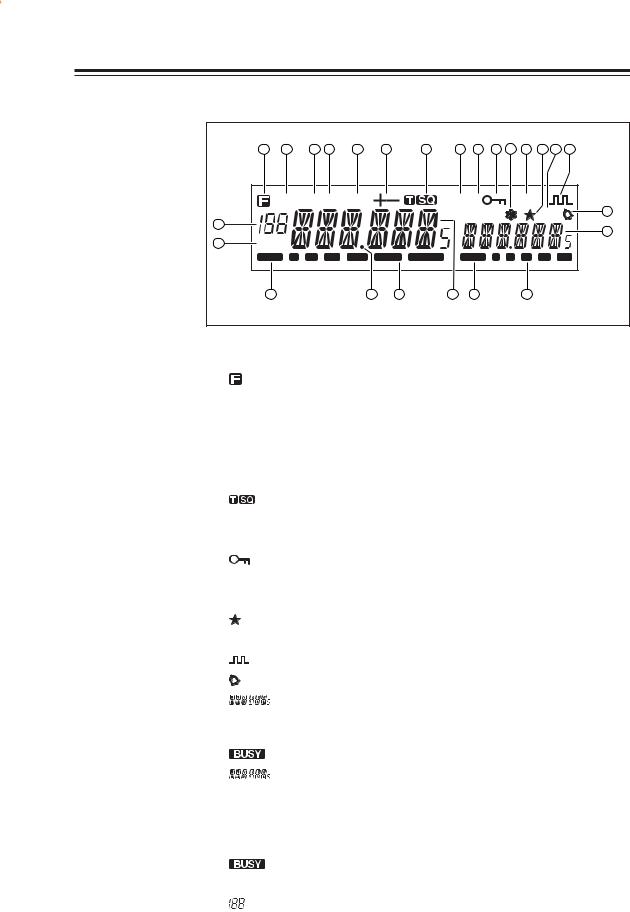
Display
|
1 |
2 |
3 |
4 |
5 |
|
6 |
7 |
8 |
9 |
10 |
11 |
12 |
13 |
14 |
15 |
|
AM MiLo Nar |
|
|
|
DCS |
|
TNC |
|
|
|||||||
|
|
|
|
|
|
|
|
|
|
SUB |
|
|
R |
16 |
||
25 |
|
|
|
|
|
|
|
|
|
|
|
|
||||
|
|
|
|
|
|
|
|
|
|
|
|
|
|
|
17 |
|
|
SQL |
|
|
|
|
|
|
|
|
|
|
|
|
|
||
24 |
|
|
|
|
|
|
|
|
|
|
|
|
|
|
||
|
BUSY |
1 |
3 |
5 |
7 |
|
9 |
|
|
BUSY |
|
|
|
|
|
|
|
23 |
|
|
|
|
22 |
21 |
|
20 |
19 |
|
|
18 |
|
|
|
No. |
Key |
Function |
1 |
|
Appears when FUNC Key is pressed. |
|
|
|
2 |
AM |
Appears during AM reception. |
|
|
|
3 |
Mi |
Appears when transmission power is set to MID. |
|
|
|
4 |
Lo |
Appears when transmission power is set to LOW. |
|
|
|
5 |
Nar |
Appears when in narrow band reception mode. |
|
|
|
6 |
+/- |
Appears when setting the shift. |
7 |
|
Appears when setting the tone squelch. |
8 |
DCS |
Appears when setting the DCS. |
9 |
SUB |
Appears when SUB band is on the MAIN side.* |
10 |
|
Appears when setting the key lock. |
11 |
* |
Appears when setting the theft alarm function. |
12 |
TNC |
Appears when in packet mode (Optional EJ-50U required). |
13 |
|
Appears when SUB band is in the memory mode or call mode. |
14 |
R |
Appears when the reverse function is activated. |
15 |
|
Appears when in the digital voice communication mode.** |
16 |
|
Appears when setting the bell (pager) function. |
17 |
|
Indicates the frequency or memory name on the SUB side |
18 |
S Meter |
Indicates the relative signal strength level of transmission/ |
|
|
reception on the SUB side. |
19 |
|
Appears when a signal is being received on the SUB side. |
20 |
|
Indicates the frequency or memory name on the MAIN side. |
21 |
S Meter |
Indicates the relative signal strength level of transmission/ |
|
|
reception on the MAIN side. |
22 |
.Decimal point |
Appears when changing the DCS decode settings. |
|
|
Disappears when setting Memory Channel skip. |
23 |
|
Appears when a signal is being received on the MAIN side. |
24 |
SQL |
Appears when setting the squelch level. |
25 |
|
Indicates memory numbers in the memory mode. |
*SUB band is the band exclusive for reception when in V-V/U-U.
** T version only. Optional EJ-47U required.
13
Part Names and Functions
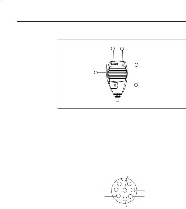
Microphone EMS-53 (Standard)*
*If the version you have purchased contained EMS-57 Multifunction microphone, please also refer page 55.
2 1
5
3
4
No. |
Key |
Function |
1 |
UP |
Increase the frequency, memory channel number, or setting value. |
2 |
DOWN |
Decrease the frequency, memory channel number, or setting value. |
|
|
|
3 |
PTT |
Press the PTT(Push-To-Talk)key to transmit. |
|
|
|
4 |
Lock Switch |
Locks out the UP and DOWN keys. |
5 |
MIC |
Speak here during transmission. |
Mic. Connector Diagram (While looking in the front view of the connector)
|
|
|
GND |
MIC |
1 |
7 |
MIC GND |
PTT |
2 |
8 6 |
REMOTE |
DOWN |
3 |
5 |
DC 5V |
|
|
4 |
|
UP
14
Basic Operations
Turning the unit on and off
By pressing the PWR key the power is turned on. By pressing the PWR key again, the power is turned off. Refer page 9 for external power control.
PWR key
|
|
|
|
|
|
|
|
|
|
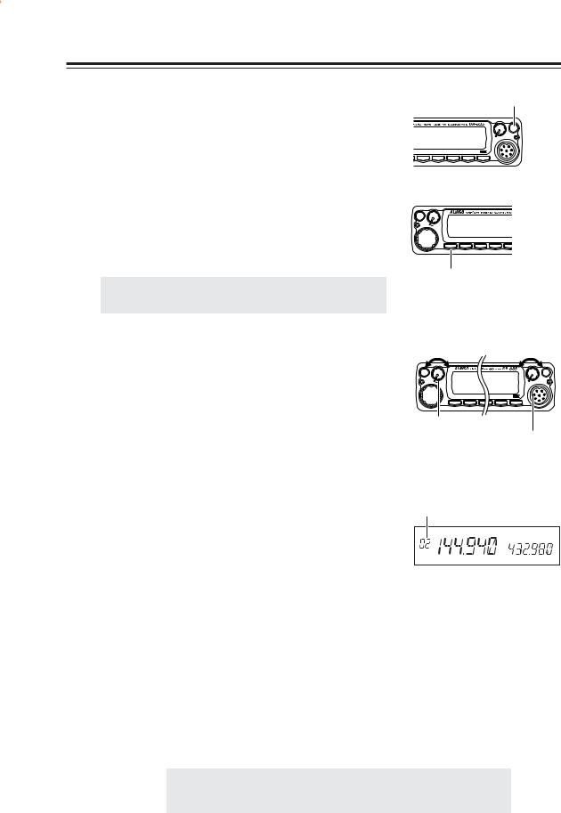
Switching the MAIN band
Pressing the BAND key will switch the MAIN band between the VHF band and the UHF band.
The MAIN band allows transmission and reception. The SUB band only allows reception. The MAIN band and the SUB band can receive simultaneously.
IMPORTANT: On the SUB side, no settings other than the fre-
quency and S meter are indicated.
Audio Volume level setting
The volume of the MAIN band is adjusted by the VOL knob on the MAIN side, and the volume of the SUB band by the VOL knob on the SUB side.
Rotate the VOL knob clockwise to increase the audio level, counterclockwise to decrease.
Squelch level setting
|
|
BAND Key
Volume |
|
|
Volume |
||
low |
high |
low |
high |
||
MW |
|
|
|
|
|
V/M |
|
|
|
|
PWR |
MAIN |
MAIN |
|
|
SUB |
SUB |
TX/RX |
|
|
RX |
||
|
VOL |
|
|
VOL |
|
|
VV/UU |
RX BAND |
SHIFTET DIGITAL |
SET |
|
|
BAND |
CALL |
MHz SQL |
FUNC |
|
MAIN side VOL knob
SUB side VOL knob
Adjust threshold level of the squelch. A squelch eliminates the background noise when a signal is not received. To set squelch level on the MAIN band side,
1. Press SQL Key.
[SQL] icon appears on the display and the squelch level will be shown on it.
2. By rotating the main dial or by using the UP/ DOWN keys on the microphone, adjust the squelch level to the desired level.
3. When completing the setting, press PTT or any key on the front panel other than the Band key. Then the display will return to the original status; or if there are no operations for 5 seconds, the unit will automatically complete the setting and the display will return to the original status.
Squelch level setting on the SUB band
Squelch level
SQL
To set the squelch level on the SUB band, press the BAND key while [SQL] appears.
NOTE: • 21 levels, between (00) and (20), are available for the squelch level. (Higher level settings will make the squelch more difficult to open.)
• The default level is 02.
15

Basic Operations
VFO mode
VFO tuning is set as the default mode at the factory. VFO (variable frequency oscillator) allows you to change the frequency in accordance with the selected channel step as you rotate the main dial or by using the UP/DOWN keys on the microphone. VFO mode is also used to program the data to be stored in the memory channels or to change the parameter settings of the transceiver.
1. Identify the current mode by checking the display. If a “M” or “C” icon is NOT displayed on it, the unit is already in the VFO mode.
If memories have not been programmed, the unit cannot be switched to the memory mode.
2. Otherwise press “V/M” key until those icons are gone.
Changing frequency by channel step
Rotate the main dial clockwise to increase the frequency, counterclockwise to decrease. The UP/DOWN keys on the microphone act in the same way.
Changing frequency by 1 MHz step
This will enable a quick change of frequency in 1 MHz steps:
1. Press MHz key. The digits after 100 kHz will disappear from the display.
2. Follow the same sequence as above to change the value.
VFO mode
Memory mode
|
MW |
|
|
|
|
|
|
Frequency |
V/M |
MAIN Frequency |
|
||||
TX/RX |
|
||||||
|
MAIN |
|
|
|
|
|
|
decrease |
|
VOL |
increase |
|
|
||
|
|
|
|
||||
|
|
|
VV/UU |
RX BAND |
SHIFT |
LOCK |
PACK |
|
|
|
BAND |
CALL |
MHz |
TS/DCS |
H/L |
Dial
16
Basic Operations
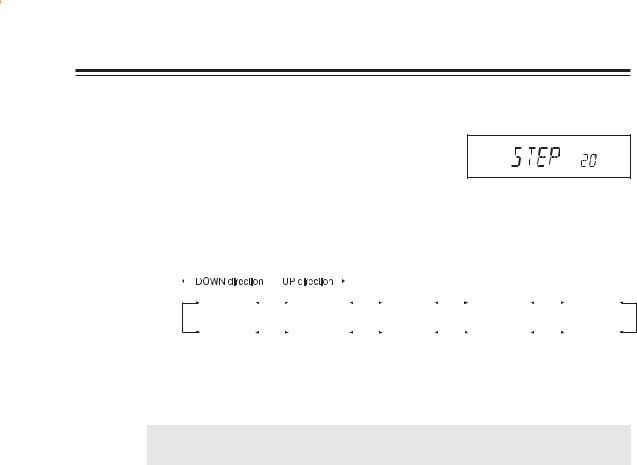
Setting the channel step
1. When the unit is in VFO mode, enter into the SET mode and select the channel step setting display. (Refer to page 26 to 28 for SET mode).
Channel step setting display (default)
2.
3.
The current channel step will be displayed.
You can change the channel step as below by rotating the dial.
STEP 5 |
|
STEP 8.33 |
|
STEP 10 |
|
STEP 12.5 |
|
STEP 15 |
(5 kHz) |
|
(8.33 kHz) |
|
(10 kHz) |
|
(12.5 kHz) |
|
(15 kHz) |
STEP 100 |
|
STEP 50 |
|
STEP 30 |
|
STEP 25 |
|
STEP 20 |
(100 kHz) |
|
(50 kHz) |
|
(30 kHz) |
|
(25 kHz) |
|
(20 kHz) |
4. Pressing any key other than the FUNC key or SQL key on the unit will complete the setting and the display will return to the original status.
IMPORTANT: By changing the channel step frequency, settings below 10kHz may be auto-
matically corrected.
17

Basic Operations
Shift Direction and Offset frequency setting
Conventional repeaters are operated in the DUPLEX mode, which receives an incoming signal on one frequency and re-transmits on another. The difference between these two frequencies is called the offset frequency. The offset is variable between 0 to 99.995MHz on this unit.
1. After pressing the FUNC key, and pressing the MHz key while [F] appears on the display, the display will show the current status of the offset frequency and the shift direction. By repeatedly pressing the MHz key, shift direction will be changed as shown to the right.
At –600kHz
- 0.600  + 0.600
Shift release (off)
2. By rotating the dial (or by pressing the UP/ DOWN key) while the shift frequency is displayed, one click will change the frequency by one channel step.
3. After pressing the FUNC key, rotating the dial will change the frequency by 1MHz depending on which direction the dial is rotated (or if the Mic UP/DOWN key is pressed).
4. Pressing the PTT key or the V/M key will complete the setting and the display will return to the original status.
18
Loading...