


WIDE BAND COMMUNICATION RECEIVER
DJ-X11
Instruction Manual
WILD |
GAIN |
||
1 |
2ABC |
||
MODE |
|||
TONE |
|||
4GHI |
|||
5JKL |
|||
NAME |
|||
PRIO |
|||
7 |
PQ |
||
8TUV |
|||
F |
RS |
||
TUNE |
|||
SCAN |
|||
ATT
3DEF
LINK
6MNO
AUDIO
9WX YZ
SET |
MAIN |
|
CLR |
||
SHIFT |
SUB |
|
0 |
||
M V |
||
STEP |
||
SCOPE |
||
ENT |
||
|
||
MW |
||
V/P/M |
||
DJ-X11
Thank you for purchasing your new Alinco receiver. This instruction manual contains important safety and operating instructions. Please read this manual carefully before using the product and keep it for future reference.
ALINCO, INC

NOTICE / Compliance Information Statement
NOTICE / Compliance Information Statement
This equipment has been tested and found to comply with the limits for a Class B digital device, pursuant to part 15 of the FCC Rules.
These limits are designed to provide reasonable protection against harmful interference in a residential installation.
This equipment generates, uses, and can radiate radio frequency energy and, if not installed and used in accordance with the instruction manual, may cause harmful interference to radio communications. However, there is no guarantee that interference will not occur in a particular moudulation. If this equipment does cause harmful interference to radio or television reception, which can be determined by turning the equipment off and on, the user is encouraged to try to correct the interference by one or more of the following measures:
•Reorient or relocate the receiving antenna.
•Increase the separation between the equipment and receiver.
•Connect the equipment into an outlet on a circuit different from that to which the receiver is connected.
•Consult the dealer or an experienced radio/TV technician for help.
Tested to Comply
With FCC Standards
FOR HOME OR OFFICE USE
Information in this document is subject to change without notice or obligation. All brand names and trademarks are the property of their respective owners. Alinco cannot be liable for pictorial or typographical inaccuracies. Some parts, options and/or accessories are unavailable in certain areas. Changes or modifications not expressly approved by the party responsible for compliance could void the user’s authority to operate the equipment.
Wide Band Communication Receiver DJ-X11T
This device complies with Part 15 of the FCC Rules. Operation is subject to the following two conditions: (1) This device may not cause harmful interference, and
(2) this device must accept any interference received, including interference that may cause undesired operation.
Manufacturer:
ALINCO, INC.
Yodoyabashi Daibiru Building 13th Floor
4-4-9, Koraibashi, Chuo-ku, Osaka 541-0043, JAPAN
2

NOTICE / Compliance Information Statement
Conformity Information
Alinco, Inc. Electronics Division hereby declare on our sole responsibility that the product(s) listed below comply the essential requirements of the Directive 1999/5/ EC, The council of 3/9/99 on Radio Equipment and Telecommunication Terminal Equipment and the mutual recognition of their conformity and with the provisions of Annex, after having performed the required measurements at Notified Bodies per Standards, and relative certificate(s) or document(s) can be reviewed at http:// www.alinco. com/Ce/
DJ-X11E: Wide Band Communication Receiver |
0.05 - 1299.99995MHz |
||
DJ-X11EGR: Portable broadcast/hamband Receiver |
0.522 |
- 1.62000MHz |
|
|
53.75 |
- 67.7500MHz |
|
|
87.60 |
- 107.9000MHz |
|
|
144.00 |
- 145.99995MHz |
|
|
180.75 |
- 229.7500MHz |
|
|
430.00 |
- 439.99995MHz |
|
|
476.75 |
- 860.7500MHz |
|
|
|
1260.00 - 1299.99995MHz |
Function: |
DJ-X11E |
DJ-X11EGR |
Inversion scramble decoder: |
Available |
N/A |
DJ-X11E is authorized for use in all EU and EFTA member states except for Greece. DJ-X11EGR is authorized for use in all EU and EFTA member states.
DJ-X11E : Band-plan setting instruction
In Europe, there are slight differences in frequency allocation country by country. Therefore the DJ-X11E has been preprogrammed with different VFO and Preset tables(band-plans) so that it will become handy when you travel. Select one of the band-plans by pressing the numeric key as instructed below when turning on the unit.
The band plan
Hold 2key while turning on : Pan-Europe
Hold 3key while turning on : UK
Please refer(P. 110)for the details of the band-plans.
Copyright © All rights reserved. No part of this document may be reproduced, copied, translated or transcribed in any form or by any means without the prior written permission of Alinco. Inc., Osaka, Japan, English Edition Printed in Japan.
3

Warning
Warning
To prevent any hazard during operation of Alinco's radio product, in this manual and on the product you may find symbols shown below. Please read and understand the meanings of these symbols before starting to use the product.
Danger |
This symbol is intended to alert the user to an immediate danger that |
|
may cause loss of life and property if the user disregards the warning. |
||
|
||
|
|
|
Alert |
This symbol is intended to alert the user to a possible hazard that |
|
may cause loss of life and property if the user disregards the warning. |
||
|
||
|
|
|
Caution |
This symbol is intended to alert the user to a possible hazard that may |
|
cause loss of property or injure the user if the warning is disregarded. |
||
|
||
|
|
|
|
|
|
|
Alert symbol. An explanation is given. |
|
|
|
|
|
Warning symbol. An explanation is given. |
|
|
|
|
|
Instruction symbol. An explanation is given. |
|
|
|
|
Alert |
|
■ Environment and condition of use
Do not use this product in close proximity to other electronic devices, especially medical ones. It may cause interference to those devices.
Keep the radio out of the reach of children.
In case a liquid leaks from the product, do not touch it. It may damage your skin. Rinse with plenty of cold water if the liquid contacted your skin.
Never operate this product in facilities where radio products are prohibited for use such as aboard aircraft, in airports, in ports, within or near the operating area of business wireless stations or their relay stations.
Use of this product may be prohibited or illegal outside of your country. Be informed in advance when you travel.
The manufacturer declines any responsibilities against loss of life and/or property due to a failure of this product when used to perform important tasks like life-guarding, surveillance, and rescue.
4

Warning
Risk of explosion if battery is replaced with an incorrect type.
Dispose of, or recycle used batteries according to your local regulations.
The manufacturer declines any responsibilities against loss of life and property due to a failure of this product when used with or as a part of a device made by third parties.
Use of third party accessory may result in damage to this product. It will void our warranty for repair.
■ Handling this product
Be sure to reduce the audio output level to minimum before using an earphone or a headset. Excessive audio may damage hearing.
Do not open the unit without permission or instruction from the manufacturer. Unauthorized modification or repair may result in electric shock, fire and/or malfunction.
Do not operate this product in a wet place such as shower room. It may result in electric shock, fire and/or malfunction.
Do not place the product in a container carrying conductive materials, such as water or metal in close proximity to the product. A short-circuit to the product may result in electric shock, fire and/or malfunction.
■ About chargers
Do not use adapters other than having the specified voltage. It may result in electric shock, fire and/or malfunction.
Do not plug multiple devices using an adapter into a single wall outlet. It may result in overheating and/or fire.
Do not handle adapter with a wet hand. It may result in electric shock.
Securely plug the adapter into the wall outlet. Insecure installation may result in short-circuit, electronic shock and/or fire.
Do not use the adapter if the plug or socket contacts are dirty. Overheating and/or short-circuiting may result in fire, electric shock and/or damage to the product.
■ About power supply
Use only appropriate, reliable power supply of correct voltage and capacity.
Do not connect cables in reverse polarity. It may result in electric shock, fire and/or malfunction.
Do not plug multiple devices including the power supply into a single wall outlet. It may result in overheating and/or fire.
Do not handle a power supply with a wet hand. It may result in electric shock.
5
Warning
Securely plug the power supply to the wall outlet. Insecure installation may result in short-circuiting, electronic shock and/or fire.
Do not plug the power supply into the wall socket if the contacts are dirty. Short-circuit and/or overheating may result in fire, electric shock and/or damage to the product.
Do not modify or remove fuse-assembly from the DC cable. It may result in fire, electric shock and/or damage to the product.
■ Cigar-lighter cable
Do not use the cable at any other than the specified voltage. It may result in electric shock, fire and/or malfunction.
Do not handle cigar cable with a wet hand. It may result in electric shock.
■ In case of emergency
In case of the following situation(s), please turn off the product, switch off the source of power, then remove or unplug the power-cord. Please contact your local dealer of this product for service and assistance. Do not use the product until the trouble is resolved.
Do not try to troubleshoot the problem by yourself.
•When a strange sound, smoke and/or strange odor comes out of the product.
•When the product is dropped or the case is broken or cracked.
•When a liquid penetrated inside.
•When a power cord (including DC cables, AC cables and adapters) is damaged.
For your safety, turn off then remove all related AC lines to the product and its accessories from the wall outlet if a thunderstorm is likely.
■ Maintenance
Do not open the unit and its accessories. Please consult with your local dealer of this product for service and assistance.
 Caution
■ Environment and condition of use
Do not use the product in proximity to a TV or a radio. It may cause interference or receive interference.
Do not install in a humid, dusty or insufficiently ventilated place. It may result in electric shock, fire and/or malfunction.
Do not install in an unstable or vibrating position. It may result in electric shock, fire and/or malfunction when/if the product falls to the ground.
Do not install the product in proximity to a source of heat and humidity such as a heater or a stove. Avoid placing the unit in direct sunlight.
|
Be cautious of a dew formation. Please completely dry the product before use when |
6 |
it happens. |
|

Warning
■ About receiver
Be cautious of the whip antenna when carried in your shirt-pocket etc. It may make contact with your eye and cause injury.
Do not connect devices other than specified ones to the jacks and ports on the product. It may result in damage to the devices.
Turn off and remove the power source (AC cable, DC cable, battery, cigar cable, charger adapter etc.) from the product when the product is not in use for extended period of time or in case of maintenance.
Never pull the cord alone when you unplug AC cable form the wall outlet.
Use a clean, dry cloth to wipe off dirt and condensation from the surface of the product. Never use thinner or benzene for cleaning.
■ About power supply
Use only reliable power supply of specific DC output range and be mindful of the polarity of the cable and DC-jack.
Always turn off the power supply when connecting or disconnecting the cables.
When using an external antenna, make sure that the antenna ground is not common with the ground of the power supply.
European users: When a unit is powered from an external DC power source (adapter, power supply, cigar-plug etc.), make sure that this power supply has approval to the level of IEC/EN 60950-1.
■ Lightning
Any person is not safe outdoor during thunderstorm and lightning. This condition is getting worse if somebody keeps a hand-held radio; chances of being hit by lightning are doubled since lightning may hit a radio antenna as well. At this time, there is no hand-held radio having any kind of protection against lightning current (which is higher than 10 kA.). Note also that no car provides adequate protection of its passengers or drivers against lightning as well. Therefore, Alinco will not take responsibility for any danger associated with using its hand-held radios outdoor or inside the car during lightning.
■ Notice to California resident users
The Safe Drinking Water and Toxic Enforcement Act of 1986 of the State of California determines that lead and cadmium are considered carcinogens and reproductive toxicants. The product that comes with this manual is free from dangerous materials such as lead and cadmium as per RoHS order of EU.
■ Limited Power Source
Please note that the receiver enclosure only provides mechanical protection of its internal parts; it will not contain a fire within the device if the fire starts under certain fault conditions. Alinco will not take responsibility for any fire hazard associated with powering the receiver or charging its batteries using a power source which does not belong to the limited power sources in the meaning of EN 60950-1. Excluded from possible use with the receiver are most car cigarette lighters and some DC (AC/DC) power supplies. Make sure that the power supply used with the receiver is a limited power source.
7

Introduction
Introduction
Thank you very much for purchasing this excellent Alinco receiver. Our products are ranked among the finest in the world. This radio has been manufactured with state of the art technology and it has been tested carefully at our factory. It is designed to operate to your satisfaction for many years under normal use.
PLEASE READ THIS MANUAL COMPLETELY TO LEARN ALL THE FUNCTIONS THE PRODUCT OFFERS. WE MADE EVERY ATTEMPT TO WRITE THIS MANUAL TO BE AS COMPREHENSIVE AND EASY TO UNDERSTAND AS POSSIBLE. IT IS IMPORTANT TO NOTE THAT SOME OF THE OPERATIONS MAY BE EXPLAINED IN RELATION TO INFORMATION IN PREVIOUS CHAPTERS. BY READING JUST ONE PART OF THE MANUAL, YOU RISK NOT UNDERSTANDING THE COMPLETE EXPLANATION OF THE FUNCTION.
“TV” as used in this manual refers to analog television.
8

Table of Contents
Table of Contents
1.Features …………………………………………………………………12
2.Checking the Accessories ………………………………………………13
3.Attaching Accessories ……………………………………………………14
3-1 Antenna…………………………………………………………………………………… 14 3-1-1 Attaching the antenna …………………………………………………………… 14 3-1-2 Removing the antenna ………………………………………………………… 14 3-2 Hand Strap ……………………………………………………………………………… 14
3-3 Belt Clip…………………………………………………………………………………… 15 3-3-1 Attaching the belt clip …………………………………………………………… 15 3-3-2 Removing the belt clip…………………………………………………………… 15 3-4 Battery Pack……………………………………………………………………………… 15 3-4-1 Attaching the battery pack ……………………………………………………… 15 3-4-2 Removing the battery pack …………………………………………………… 16
3-5 Charging the Battery Pack through the DC Jack …………………………………… 17 3-6 Charging the Battery Pack with the Charger ………………………………………… 18 3-7 Preventing the Battery Pack from Short-circuiting …………………………………… 18 3-8 Dry Battery Case ………………………………………………………………………… 19 3-9 Battery Level Icons ……………………………………………………………………… 20
4. Part Names and Operation ……………………………………………21
4-1 Part Names and Functions of the Receiver ………………………………………… 21 4-1-1 Top and front panels …………………………………………………………… 21 4-1-2 Side panels ……………………………………………………………………… 22 4-1-3 Key operation …………………………………………………………………… 23 4-2 LCD Display ……………………………………………………………………………… 24
5. Basic Operation …………………………………………………………25
5-1 Turning the Power ON ………………………………………………………………… 25
5-2 Tuning the Frequency…………………………………………………………………… 25
5-3 Adjusting the Volume Level …………………………………………………………… 25
5-4 Adjusting Squelch Level ………………………………………………………………… 26
5-4-1 Operating procedure …………………………………………………………… 26
5-5 Monitor function ………………………………………………………………………… 27
5-6 Mute Function …………………………………………………………………………… 27 5-7 Selecting the Band to Operate ………………………………………………………… 28 5-7-1 Mono-band operation …………………………………………………………… 28
6. Operating Modes …………………………………………………………29
6-1 Setting frequencies in VFO mode……………………………………………………… 30 6-2 Setting the Channel Step Frequency ………………………………………………… 30 6-3 1 MHz UP/DOWN Operation…………………………………………………………… 30 6-4 Setting Frequencies through Direct Input …………………………………………… 31 6-5 Setting frequencies in Preset mode …………………………………………………… 31 6-6 Receiving Operation …………………………………………………………………… 32
7. Memory Mode ……………………………………………………………34
7-1 Memory Types and Usage ……………………………………………………………… 34
7-2 Programming a Memory Channel……………………………………………………… 35 7-3 Calling Up a Memory Channel ………………………………………………………… 38 7-4 Deleting a Memory Channel …………………………………………………………… 38 7-5 Editing a Memory Channel……………………………………………………………… 39
1
2
3
4
5
6
7
8
9
10
11
12
13
14
15
16
17
9

Table of Contents
7-6 Quick Memory …………………………………………………………………………… 40 7-6-1 Programming a memory channel to the quick memory……………………… 40 7-6-2 Calling up a memory channel from the quick memory ……………………… 40 7-7 Memory Skip Function ………………………………………………………………… 40
7-8 Memory Naming Function ……………………………………………………………… 41
8. Functions Assigned to the Key Pad ……………………………………48
8-1 Shortcut Function ……………………………………………………………………… 48 8-2 Receiving Sensitivity (RF Gain) Adjustment and Attenuator Function …………… 48 8-3 Switching the Modulation Mode ……………………………………………………… 50 8-4 Setting the Tone Squelch/DCS ………………………………………………………… 51 8-4-1 Tone Squelch function…………………………………………………………… 51 8-4-2 DCS function …………………………………………………………………… 53 8-5 Bank Link Setting Function …………………………………………………………… 54
8-6 Priority Monitoring Function …………………………………………………………… 55 8-7 Received Sound Quality Adjustment Function ……………………………………… 56 8-8 Frequency Shift Function ……………………………………………………………… 57 8-8-1 Setting the Frequency Shift function…………………………………………… 57 8-8-2 Using the function ……………………………………………………………… 57 8-9 Changing the Channel Step …………………………………………………………… 58
8-10 Channel Scope Function ……………………………………………………………… 59 8-10-1 VFO Channel Scope …………………………………………………………… 60 8-10-2 Memory Channel Scope ……………………………………………………… 61 8-11 Copying the Memory Channel Data into VFO Mode ……………………………… 62 8-12 F Tuning Function ……………………………………………………………………… 62
9. Useful Functions …………………………………………………………63
9-1 Key-lock Function ……………………………………………………………………… 63 9-1-1 Key-lock procedure ……………………………………………………………… 63 9-1-2 Operations available while the Key-lock is active …………………………… 63 9-2 Scanning Function ……………………………………………………………………… 64
9-3 VFO Scan ………………………………………………………………………………… 64
9-4 Preset Scan ……………………………………………………………………………… 65
9-5 Memory scan …………………………………………………………………………… 65
9-6 Programmed Scan ……………………………………………………………………… 66
9-7 Tone Scan………………………………………………………………………………… 66
9-8 DCS Scan………………………………………………………………………………… 67
9-9 Sweep Scan ……………………………………………………………………………… 68
9-10 Bug Detector Function ………………………………………………………………… 69 9-10-1 Operating procedure in Silent mode ………………………………………… 69 9-10-2 Operating procedure in Sound mode ………………………………………… 70 9-10-3 Mode coupling setting of the Bug Detector function ……………………… 71 9-10-4 Sensitivity setting of the Bug Detector function …………………………… 72
10. Set Mode Configurations ………………………………………………73
10-1 Receiver Setting ……………………………………………………………………… 74 10-1-1 Bar antenna setting …………………………………………………………… 74 10-1-2 Earphone antenna setting …………………………………………………… 75 10-1-3 Preset mode setting …………………………………………………………… 75 10-1-4 CW setting ……………………………………………………………………… 76 10-1-5 Detected signal output function ……………………………………………… 76 10-1-6 F Tuning function operation setting ………………………………………… 77 10-1-7 IQ signal output function ……………………………………………………… 77
10-2 Screen Display Setting………………………………………………………………… 78
10-2-1 Language setting ……………………………………………………………… 78
10-2-2 Illumination setting……………………………………………………………… 78
10-2-3 Contrast setting ………………………………………………………………… 79 10-2-4 Font size setting………………………………………………………………… 79 10-2-5 Font style setting ……………………………………………………………… 79 10-2-6 Welcome screen setting ……………………………………………………… 80
10
Table of Contents
10-3 Power and Battery Setting …………………………………………………………… 81 10-3-1 Auto power off setting ………………………………………………………… 81 10-3-2 Battery setting ………………………………………………………………… 82 10-3-3 Battery save function setting ………………………………………………… 82 10-4 Key Assignment Setting ……………………………………………………………… 83 10-4-1 Key-lock mode setting ………………………………………………………… 83 10-4-2 Set mode exit time setting …………………………………………………… 84 10-4-3 Band transition setting ………………………………………………………… 84 10-4-4 Right/left dial function setting ………………………………………………… 85 10-4-5 Upper/lower dial function setting……………………………………………… 85 10-4-6 Assigning a function to the WILD key………………………………………… 86 10-4-7 Assigning a function to the MONI key ……………………………………… 86 10-4-8 Setting the band operated with the MONI key ……………………………… 86 10-4-9 MONI key activation setting …………………………………………………… 87 10-4-10 MONI key setting……………………………………………………………… 87 10-4-11 Remote COM port setting …………………………………………………… 88 10-5 Scan Setting …………………………………………………………………………… 88 10-5-1 Scan mode setting……………………………………………………………… 88 10-5-2 Priority Monitoring interval setting …………………………………………… 89 10-5-3 Priority Monitoring duration setting …………………………………………… 90 10-5-4 Skip scan operation setting …………………………………………………… 90 10-5-5 Scan speed setting …………………………………………………………… 91 10-6 Memory Setting ………………………………………………………………………… 91 10-6-1 Write-protect (memory protection) function setting ………………………… 91 10-6-2 Memory name display setting ………………………………………………… 92 10-7 Sound Setting ………………………………………………………………………… 92 10-7-1 Beep setting …………………………………………………………………… 92 10-7-2 Bell function setting …………………………………………………………… 93 10-7-3 Voice Guidance function setting ……………………………………………… 94 10-8 Remote Controller Setting …………………………………………………………… 95
11.Channel Display Mode …………………………………………………96
12.Cable-clone and PC Connection Functions …………………………97
12-1 PC Connection and Connection Ports ……………………………………………… 97 12-2 Cable-Clone Receiving Data ………………………………………………………… 99 12-3 Cable-Clone Transferring Data ………………………………………………………100
13. Reset Function ……………………………………………………… 101
13-1 Reset ……………………………………………………………………………………101
14. Using the Optional Remote Controller …………………………… 102
14-1 Using the Remote Controller …………………………………………………………102
14-1-1 Top/Bottom/Front panels ………………………………………………………102
14-1-2 Side panel ………………………………………………………………………102
14-2 Connecting the Remote Controller……………………………………………………103
14-3 Remote Controller Functions …………………………………………………………103
15. Maintenance and Reference ……………………………………… 104
15-1 Troubleshooting…………………………………………………………………………104
15-2 Optional Accessories List………………………………………………………………105
15-3 After-sales Service ……………………………………………………………………106
16.Index ………………………………………………………………… 107
17.Specifications ………………………………………………………… 109
17-1 Specifications……………………………………………………………………………109
17-2 The Band-plans ………………………………………………………………………… 110 17-2-1 Switching the main band ……………………………………………………… 110 17-2-2 Switching the sub band ……………………………………………………… 112
1
2
3
4
5
6
7
8
9
10
11
12
13
14
15
16
17
11

|
1. Features |
1 |
1. Features |
The DJ-X11 is a multifunctional receiver which receives a wide range of radio signals from low-frequency (LF) signals to ultra-high-frequency (UHF) signals.
It provides the following features:
1Receives a wide range of frequencies - between 0.05 and 1299.99995 MHz - including aviation radio and business communication frequencies.
2Dual-frequency simultaneous reception for receiving signals with main and sub bands simultaneously. (The frequencies which can be received with the sub band are limited.)
3Various reception modes supported including SSB/CW as well as FM/ WFM/AM. The DJ-X11 can receive not only AM/FM radio signals and analog TV sounds, but also SSB mode signals which are used for amateur band Morse code and ship/aviation radios.
4F Tuning function which quickly tunes to the very strong RF signal and receives it, if such signal may exist.
5Built-in bar-antenna receives AM radio , eliminating the need to attach an external antenna.
6Earphone cord can be used as an antenna to receive FM broadcast and other stronger signals without using an external antenna.
7Automatic input switching. By connecting the optional remote controller to the earphone jack and connecting an MP3 player or other portable audio device to the controller, you can listen to music under normal conditions and hear receiver messages when the DJ-X11 receives any signals.
8Bug Detector function in two modes. This function notifies you of the possible presence of a bugging device (wireless microphone) with a display, an alarm and a voice announcement.
9Clone function for copying settings and various data between the receiver units. It is also possible to connect the receiver to a personal computer to edit settings and data.
10Tone Squelch and DCS, cut off shrill and rattling noises so that only the target sound can be heard.
11Scan speed is selectable from 3 levels. Select a fast scan speed to detect strong signals, and select a slower scan speed to detect weak signals.
12Voice Guidance function which announces the result of key operations or the Bug Detector function in English.
12

2. Checking the Accessories
2. Checking the Accessories |
2 |
The package of the DJ-X11 contains the following items. Check that all items are |
included in your package before using the receiver.

 Instruction Manual (this manual)

 Warranty certificate (T/K versions only)

 Dry battery case (EDH-36)

 Lithium ion battery pack (EBP-74 3.7 V, 1800 mAh)

 AC adapter (EDC-139; T/K EDC-140; E/EGR)

 Charger stand (EDC-174)

 Whip antenna (SMA/EA-154)
Belt clip (EBC-23)
Hand strap
Standard accessory may vary depending on the model you have purchased. Please consult with your Alinco dealer of the details before purchase.
13

3. Attaching Accessories
3. Attaching Accessories
3 3-1 Antenna
3-1-1 Attaching the antenna
1Hold the antenna at its base and rotate it clockwise (to the right).
2When you cannot rotate the
antenna further, confirm that it is securely attached to the receiver.
• To avoid breakage, the supplied antenna is made of a more flexible material than that of typical antennae.
MEMO • This connector is also used for the connection of an external antenna.
3-1-2 Removing the antenna
1 Rotate the antenna counterclockwise (to the left).
3-2 Hand Strap
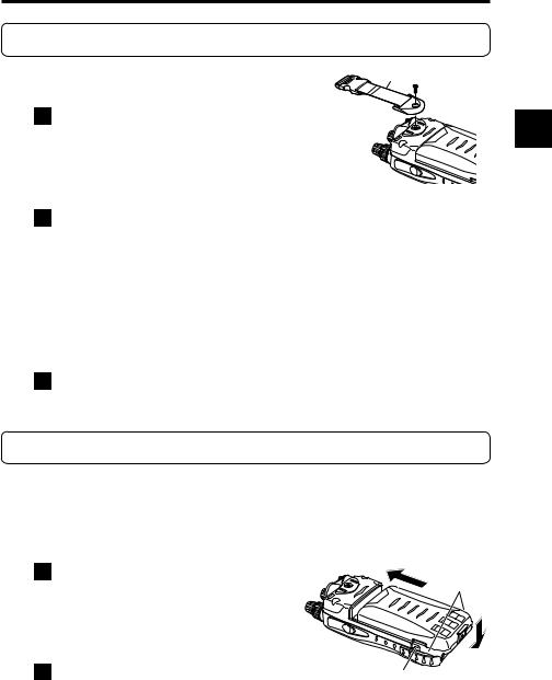
1Attach the hand strap to the hole on the rear of the receiver as shown in the figure.
Hand strap
14
3. Attaching Accessories
3-3 Belt Clip
3-3-1 Attaching the belt clip
1Align the belt clip with the groove at the rear of the receiver to secure it, insert the screw into the hole and rotate it clockwise (to the right).
Belt clip
3
2Check that the belt clip is securely attached to the receiver.
*The screw may become loose during use. Check the tightness from time to time.
*The belt clip can be adjusted so that it can be used for a belt of approximately 8 cm width at maximum.
3-3-2 Removing the belt clip
1Rotate the screw counterclockwise (to the left) and remove the belt clip.
3-4 Battery Pack
For the procedure for charging the lithium ion battery pack (EBP-74), refer to “Charging the Battery Pack with the Charger” (P. 18) and “Charging the Battery Pack through the DC Jack” (P. 17).
3-4-1 Attaching the battery pack
1Align the hooks of the battery pack with the grooves of the receiver and push in the battery pack in the direction of arrow (1).
2Slide the lock lever at the bottom of the battery pack in the direction of arrow (2).
(1)
Hooks
(2)
Groove
15
3. Attaching Accessories
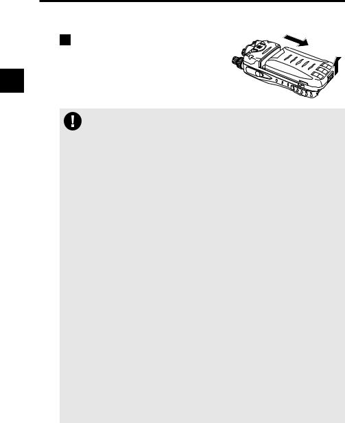
3-4-2 Removing the battery pack
|
1 Slide the lock lever at the |
(2) |
||
|
|
|||
|
bottom of the battery pack in |
|
||
3 |
the direction of arrow (1) and |
|
||
remove the battery pack (2). |
(1) |
|||
|
||||
|
• |
The battery pack is not fully charged when shipped. You need to |
||
|
CAUTION • |
charge it after purchase before use. |
|
|
|
The battery pack must be charged within the temperature range of 0 to |
|||
|
|
40°C. |
|
|
•Do not modify or dismantle the battery pack and do not throw it into fire or water. These actions are dangerous.
•Do not short-circuit the battery pack terminals. This may damage the equipment, or may cause burns by the heat generated from the battery. Do not charge the battery pack for an unnecessarily long time (overcharging). This may deteriorate battery performance.
•The battery pack should be stored in a dry place where the temperature range is between -10°C and +45°C. Storing the battery pack in locations with high humidity or temperatures outside the proper range may cause the battery solution to leak or the metal sections to rust.
•The battery pack is a consumable article. When the battery pack becomes exhausted extremely quickly even when it has been charged for the specified time, it may have reached the end of its life. In such a case, replace the battery pack with a new one.
•The battery pack is a recyclable resource. Do not dispose the battery pack but take it to a battery recycling center in your area. The battery pack is dedicated for use in Alinco products. It can be charged only using the applicable genuine charger or conforming receiver. Charging it with commercially-available or third-party chargers or adapters may cause a breakage or accident. Clean the electrodes of the battery pack and charger with a dry cotton swab from time to time.
•Even if you do not use the battery pack for a long time, charge it at least once every three months to prevent deterioration.
•The supplied battery pack is dedicated for use in the DJ-X11. Charging it with chargers or adapters other than specified models may cause a breakage or accident.
16

3. Attaching Accessories
3-5 Charging the Battery Pack through the DC Jack
The supplied lithium ion battery pack can be charged through the DJ-X11 by us- |
|
|
ing the supplied AC adapter and a DC power supply (6 VDC, 1 A or more: IEC/ |
|
|
EN60950 standard). It takes about six hours to fully charge the battery pack |
3 |
|
from a state of complete discharge. |
||
|
1 Attach the battery pack by referring to “Battery Pack” (P. 15).
2Connect the plug of the AC adapter into the DC jack of the DJ-X11 and plug the AC adapter into a wall outlet.
*Your AC adapter may have a different shape from the AC adapter shown in the figure.
AC adapter*
AC adapter plug
For the battery level indication during charging, refer to “Battery Level Icons” (P. 20).
• When the receiver is used with the supplied AC adapter connected, the
reception may be affected by noise; however, this is not a malfunction.
CAUTION
• Also read the precautions supplied with the optional accessories care-
fully to ensure proper use and safety.
MEMO • If the voltage of the wall outlet is not stable, the battery pack may not be charged properly.
17

3. Attaching Accessories
3-6 Charging the Battery Pack with the Charger
Using the supplied charger completes charging in about four hours from a state of complete discharge.
3 |
1 |
Connect the plug of the AC adapter to the charger. |
2 |
Plug the AC adapter into a wall |
outlet and place the DJ-X11 on the charger.
During charging, the red lamp of the charger illuminates.
When the charging is complete,the lamp goes off.
EDC-174 doesn't charge when EBP-74 is fully charged and thered lamp stays off.
• If charging fails with the battery pack attached to the receiver, try
charging the battery pack alone and check the operation.
MEMO • The battery pack can also be charged by using the optional PC connection cable (ERW-8). (About eight hours)
3-7 Preventing the Battery Pack from Short-circuiting
Take extreme caution when carrying the battery pack. A current surge caused by short-circuiting may cause a fire.
DON’T carry with metals |
DON’T carry the battery |
of any type, e.g. chains. |
pack inside bags made of |
|
conductive materials. |
|
|
DON’T place in the proximity of metals or conductives, e.g. nails, chains.
Do enclose inside a non-conductive enclosure. (bags or handkerchief made only of non-conductive material)
Do protect by spreading a non-conductive sheet on a flat surface.
18
3. Attaching Accessories
3-8 Dry Battery Case
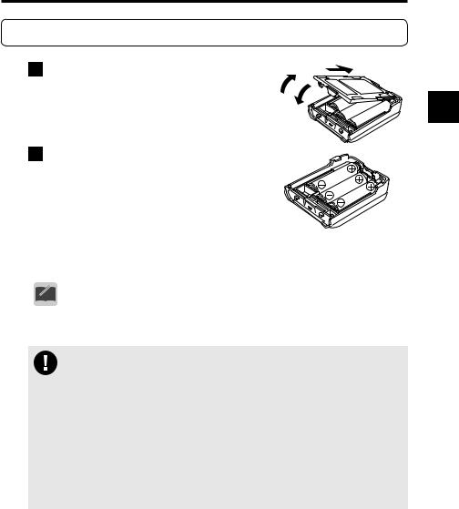
1 Push up tab (1) and remove the |
|
(2) |
|
(1) |
|
||
lid. |
3 |
||
(3) |
|||
|
|||
|
|
2 Set three AA dry batteries in the case and close the lid in the order of 2 and 3. Check that the lid is closed securely. You must use alkaline dry batteries. Manganese dry batteries cannot be used.
• To use dry batteries, read the instructions in “Battery setting” (P. 82).
MEMO
Precautions on using the dry battery case
CAUTION • Be careful of the orientation of the batteries. Inserting them in the incorrect orientation may cause electrical leakage, fire, or explosion.
•Use new dry batteries of the same type and manufacturer.
•When replacing the batteries, replace all batteries with new ones.
•Rechargeable batteries must not be used. Alinco assumes no responsibility for any property damage or physical injuries resulting from the use of rechargeable batteries.
•Clean the electrodes which make contact with the dry batteries with a clean, dry cloth or cotton swab from time to time.
•Using batteries of the wrong type may cause an explosion.
19

3. Attaching Accessories
3-9 Battery Level Icons
|
The battery icon displayed on the LCD of the DJ-X11 indicates the remaining |
|||||||||||||||||||||||||||||||||||||
|
battery power. When the battery icon indicates empty, charge the battery pack |
|||||||||||||||||||||||||||||||||||||
|
or replace the dry batteries with new ones. |
|
|
|
|
|
||||||||||||||||||||||||||||||||
3 |
|
|
|
|
|
|
|
|
|
|
|
|
|
Battery icon |
|
|
|
|
|
|
|
|
|
|
|
|
|
|
|
|
|
|
|
|
|
|||
|
|
|
|
|
A T H |
|
- DCS |
|
|
|
BS |
|
|
|
|
|
|
|
|
|
|
|
|
|
|
|
|
|
|
|
|
|
|
|
|
|||
|
|
|
|
|
|
|
|
|
|
|
|
|
|
|
|
|
|
|
|
|
|
|
|
|
|
|
|
|
|
|
|
|
||||||
|
VFO |
|
|
|
145.000 |
|
|
|
Remaining battery |
Remaining dry battery |
||||||||||||||||||||||||||||
|
001MR |
|
|
BUSY |
|
|
|
|
|
|
|
|
FM |
power is sufficient. |
power is sufficient. |
|||||||||||||||||||||||
|
|
|
|
|
|
|
|
|
||||||||||||||||||||||||||||||
|
433.000 |
|
|
|
|
|
|
|
|
|||||||||||||||||||||||||||||
|
|
|
|
|
|
|
|
|
|
|
|
|
|
|
|
|
|
|
|
|
|
|
|
|
|
|
|
|
|
|||||||||
|
000 |
|
|
BUSY |
|
|
|
|
|
|
|
|
FM |
|
|
|
|
|
|
|
|
|
|
|
|
|
|
|
|
|
|
|
|
|
||||
|
|
|
|
|
|
Remaining battery |
Remaining dry battery |
|||||||||||||||||||||||||||||||
|
|
|
|
|
|
|
|
|
|
|
||||||||||||||||||||||||||||
|
|
|
|
|
|
|
|
|
|
|
|
|
|
|
|
|
|
|||||||||||||||||||||
|
|
|
|
|
|
|
|
|
|
|
|
|
|
|
|
|
|
power is decreasing. |
power is decreasing. |
|||||||||||||||||||
|
|
|
|
|
|
|
|
|
|
|
|
|
|
|
|
|
|
Remaining battery |
Remaining dry battery |
|||||||||||||||||||
|
|
|
|
|
|
|
|
|
|
|
|
|
|
|
|
|
|
power is low. |
power is low. |
|||||||||||||||||||
|
|
|
|
|
|
|
|
|
|
|
|
|
|
|
|
|
|
|
|
|
|
|
|
|
|
|
|
|
|
|
|
|
Battery pack is being |
|||||
|
|
|
|
|
|
|
|
|
|
|
|
|
|
|
|
|
|
|
|
|
|
|
|
|
|
|
|
|
|
|
|
|
||||||
|
|
|
|
|
|
|
|
|
|
|
|
|
|
|
|
|
|
|
|
|
|
|
|
|
|
|
|
|
|
|
|
|
||||||
|
|
|
|
|
|
|
|
|
|
|
|
|
|
|
|
|
|
|
|
|
|
|
|
|
|
|
|
|
|
|
|
|
||||||
|
|
|
|
|
|
|
|
|
|
|
|
|
|
|
|
|
|
|
|
|
|
|
|
|
|
|
|
|
|
|
|
|
charged. |
|
|
|
|
|
|
|
|
|
|
|
|
|
|
|
|
|
|
|
|
|
|
|
|
|
|
|
|
|
|
|
|
|
|
|
|
|
|
|
|
|
|
|
|
|
|
|
|
|
|
|
|
|
|
|
|
|
|
|
|
|
|
|
|
|
|
|
|
|
|
|
|
|
|
|
|
|
|
|
|
|
|
|
|
|
|
|
|
|
|
|
|
|
|
|
|
|
|
|
|
|
|
|
|
|
|
|
|
|
|
|
|
|
|
|
|
|
|
|
|
|
|
When the receiver is turned OFF, “Charging” is displayed on the LCD. When the charging is complete, “Charge completed” is displayed.
20
4. Part Names and Operation
4. Part Names and Operation
4-1 Part Names and Functions of the Receiver
4-1-1 Top and front panels
(2) |
(1) |
(3) |
(4) |
||||
|
|
|
|
|
|
|
|
|
|
|
|
|
|
|
|
(5) |
|
|
|
|
|
|
|
|
WILD |
GAIN |
ATT |
SET |
|
||
|
1 |
MAIN |
|||||
|
ABC |
3DEF |
CLR |
||||
|
MODE |
2 |
|
|
|
||
(6) |
TONE |
LINK |
SHIFT |
|
|||
NAME |
5 |
|
6MNO |
0 |
M V |
||
|
4 |
GHI |
|
JKL |
|
|
SUB |
|
|
PQ |
PRIO |
AUDIO STEP |
|
||
|
7 RS |
8TUV |
WX |
ENT |
SCOPE |
||
|
F |
TUNE |
|
9 YZ |
MW |
||
|
SCAN |
|
|
V/P/M |
|||
4
(7)(8)
(9)(10)
(11)
No. |
Name |
Function |
|
(1) |
Upper main dial |
Rotate the dial to change the frequency/memory channel or |
|
|
|
to set items for the main band. Pressing this dial while |
is |
|
|
displayed switches the receiver to the mode coupling setting |
|
|
|
of the Bug Detector function. |
|
(2) |
Lower main dial |
Rotate the dial to change audio volume or set items for the |
|
|
|
main band. |
|
|
|
|
|
(3) |
Upper sub dial |
Rotate the dial to change the frequency/memory channel |
|
|
|
or set items for the sub band. Pressing this dial while |
is |
|
|
displayed switches the receiver to the sensitivity setting of |
|
|
|
the Bug Detector function. |
|
(4) |
Lower sub dial |
Rotate the dial to change audio volume or set items |
|
|
|
for the sub band. |
|
|
|
|
|
(5) |
LCD |
The status of the receiver is displayed. Refer to "LCD |
|
|
|
Display" for details. |
|
|
|
|
|
(6) |
Key pad |
Use these keys for direct frequency input or various |
|
|
|
settings. |
|
21

4. Part Names and Operation
|
|
No. |
Name |
Function |
|
|
(7) |
Antenna connector |
Attach the supplied antenna securely. To use other |
|
|
|
(SMA) |
antennae, select an antenna which has been tuned to |
|
|
|
|
operate within the specified operating frequency range. |
|
|
(8) |
Earphone jack |
Used to connect an external earphone. |
|
|
(9) |
Main RX lamp |
This lamp illuminates in green while the main band |
|
|
|
|
squelch is open. |
4 |
|
|
|
|
|
|
|
|
|
|
(10) |
Sub RX lamp |
This lamp illuminates in green while the sub band |
|
|
|
|
squelch is open. |
|
|
|
|
|
|
|
|
(11) |
Speaker |
A low-profile, built-in speaker is provided. |
4-1-2 Side panels
(12)
(15)
(13)
(14)
No. |
Name |
Function |
(12) |
FUNC key |
Use this key in combination with other keys to use |
|
|
various functions. Rotating the upper main/sub dial |
|
|
while holding down this key changes the frequency |
|
|
by 1 MHz. Holding down this key (approx. 1 second) |
|
|
activates/deactivates the Quick Key-lock function. |
|
|
|
(13) |
MONI key |
Press this key to open the squelch and hear the |
|
(LAMP key) |
received sound. |
(14) |
POWER key |
Hold down this key (approx. 1 second) to turn ON/ |
|
|
OFF the receiver. |
|
|
|
(15) |
DC jack |
This is an external power supply connection terminal. |
|
|
Connect the supplied AC adapter, or connect the |
|
|
optional cigarette lighter cable to use the receiver in a |
|
|
car. To use a stabilized power supply, be sure to use a |
|
|
power supply of 6.0 VDC and 1 A or higher. |
22

4. Part Names and Operation
4-1-3 Key operation
WILD |
GAIN |
|||
1 |
||||
2 |
|
|||
MODE |
ABC |
|||
TONE |
||||
4GHI |
||||
5 |
JKL |
|||
NAME |
|
|||
PRIO |
||||
7 |
PQ |
|||
8 |
|
|||
F |
RS |
TUV |
||
TUNE |
|
|||
SCAN |
|
|||
ATT
3DEF
LINK
6MNO
AUDIO
9WX YZ
SET |
MAIN |
|
CLR |
||
SHIFT |
SUB |
|
0 |
||
M V |
||
STEP |
||
SCOPE |
||
ENT |
||
|
||
MW |
||
V/P/M |
||
Name |
Function |
After the FUNC Key |
Hold Down the Key |
Hold Down the Key |
|
|
|
is Pressed |
(Approx. 1 Second) |
and Operate the Dial |
|
1 |
Enter 1. |
WILD key |
Program/cancel |
|
|
|
|
|
the quick |
|
|
2 |
Enter 2. |
Adjust the receiving |
|
||
memory (in |
|
||||
|
|
sensitivity. |
|
||
|
|
Memory mode). |
|
||
3 |
Enter 3. |
Set the Attenuator. |
|
||
|
|
||||
|
|
|
|
|
|
4 |
Enter 4. |
Switch the modulation mode. |
|
|
|
5 |
Enter 5. |
Set the Tone |
|
|
|
|
|
Squelch/DCS |
|
|
|
6 |
Enter 6. |
Set the bank link. |
|
- |
|
7 |
Enter 7. |
Set the memory name. |
|
||
|
|
||||
|
|
|
|
|
|
8 |
Enter 8. |
Priority Monitoring function |
|
|
|
9 |
Enter 9. |
Received Sound Quality |
|
|
|
|
|
Adjustment function |
|
|
|
0 |
Enter 0. (rev) |
Frequency Shift function |
|
|
|
. |
Enter a decimal |
Call up Set mode. |
- |
|
|
|
point. (CLR) |
|
|
||
|
|
|
|
||
ENT |
Determine the entry. |
Channel step |
|
|
|
|
|
|
|
|
|
MAIN |
Switch bands/ |
Edit the memory |
Switch the main |
Switch bands/ |
|
|
banks. |
channel. |
band between |
banks. |
|
|
|
|
dual-/mono-band. |
|
|
SUB |
Switch bands/ |
- |
Switch the sub |
|
|
|
banks. |
band between |
|
||
|
|
|
dual-/mono-band. |
|
|
SCOPE |
Channel Scope |
M V function |
|
|
|
|
function |
|
|
- |
|
V/P/M |
Switch operation |
Program/clear the |
- |
||
|
|||||
|
modes. |
memory channel. |
|
||
|
|
|
|||
SCAN |
SCAN key |
F Tuning function |
|
Select the scan |
|
|
|
|
|
mode. |
4
23
4. Part Names and Operation
4-2 LCD Display
(1) (2)(3) (4) (5) (6) (7) (8)(9) (10)
|
|
|
|
|
|
|
|
|
|
|
|
|
|
|
|
|
|
|
|
|
|
|
|
|
|
|
|
|
|
|
|
|
|
|
|
|
|
|
|
|
|
|
|
|
|
|
|
|
|
|
|
|
|
|
|
|
|
|
|
|
|
|
|
|
|
|
|
|
|
|
|
|
|
A T H |
D |
- D C S |
|
|
B S |
|
|
|
|
|
|
||||||||||
|
|
|
|
|
|
|
|
|
|
|
|
|
|
|
|
|
|
|
VFO |
|
|
|
|
(11) |
|||||||||||||||||||||||
|
|
|
(18) |
|
|
|
|
|
|
|
|
|
|
|
|
|
|
|
|
|
|
|
|
|
|
|
|
|
|
|
|
|
|
|
|
||||||||||||
|
|
|
|
|
|
|
|
|
|
|
|
|
|
|
|
|
|
|
|
|
|
|
|
|
|
|
|
|
|
|
|
|
|
||||||||||||||
|
|
|
|
|
|
|
|
|
|
|
|
|
|
|
|
|
|
|
|
|
|
|
|
|
|
|
|
|
|
|
|
|
|
|
|
|
|
|
|
|
|
|
|
|
|
||
|
|
|
(17) |
|
|
|
|
|
|
|
|
|
|
BUSY |
|
|
|
|
|
|
|
|
|
|
|
|
F M |
|
|
|
(12) |
||||||||||||||||
|
|
|
|
|
|
|
|
|
|
|
|
|
|
|
|
|
|
|
|
||||||||||||||||||||||||||||
|
|
|
|
|
|
|
|
|
|
|
|
|
|
|
|
|
|
|
|
|
|
|
|
|
|
|
|||||||||||||||||||||
4 |
|
|
(16) |
|
|
|
|
|
|
|
|
|
|
|
|
|
|
|
|
|
|
|
|
|
|
|
|
|
|
|
|
|
|
|
|
||||||||||||
|
|
|
|
|
MR |
433.000 |
|
|
|
|
|
|
|
|
|
|
|
(13) |
|||||||||||||||||||||||||||||
|
|
|
|
|
|
|
|
|
|
|
|
|
|
|
|
|
|
|
|
|
|
|
|
|
|
|
|
|
|||||||||||||||||||
|
|
(15) |
|
|
|
001 |
|
|
|
|
|
|
|
|
|
|
|
|
|||||||||||||||||||||||||||||
|
|
|
|
|
|
|
|
|
|
|
|
|
|
|
|
|
|
|
|
|
|
|
|
|
|
|
|
|
|
|
|
|
|
|
|
|
|
|
|
|
|
|
|||||
|
|
(14) |
|
|
|
00 |
0 |
|
BUSY |
|
|
|
|
|
|
|
|
|
|
|
|
F M |
|
|
|
|
|
||||||||||||||||||||
|
|
|
|
|
|
|
|
|
|
|
|
|
|
|
|
|
|
|
|||||||||||||||||||||||||||||
|
|
|
|
|
|
|
|
|
|
|
|
|
|
|
|
|
|
|
|
|
|
|
|||||||||||||||||||||||||
|
|
|
|
|
|
|
|
|
|
|
|
|
|
|
|
|
|
|
|
||||||||||||||||||||||||||||
|
|
|
|
|
|
|
|
|
|
|
|
|
|
|
|
|
|
|
|
|
|
|
|
|
|
|
|
|
|
|
|
|
|
|
|
|
|
||||||||||
|
|
No. |
|
|
|
Indication |
|
|
|
|
|
|
|
|
|
|
|
|
|
Function |
|||||||||||||||||||||||||||
|
|
(1) |
/ |
|
|
|
|
|
|
|
|
|
|
/ |
|
|
|
|
|
|
|
Appears when the [FUNC] key is pressed or |
|||||||||||||||||||||||||
|
|
|
|
|
|
|
|
|
|
|
|
|
|
|
|
|
|
|
|||||||||||||||||||||||||||||
|
|
|
|
|
|
|
|
|
|
|
|
|
|
|
|
|
|
|
|
|
|
|
|
|
|
|
|
when the Key-lock is activated (P. 63). |
|||||||||||||||||||
|
|
|
|
|
|
|
|
|
|
|
|
|
|
|
|
|
|
|
|
|
|
|
|
|
|
|
|
||||||||||||||||||||
|
|
|
|
|
|
|
|
|
|
|
|
|
|
|
|
|
|
|
|
|
|
|
|
|
|
|
|
|
|||||||||||||||||||
|
|
(2) |
|
|
|
|
|
|
|
|
|
|
|
|
|
|
|
|
|
|
|
|
|
|
|
|
|
Appears while the Auto Power OFF function is |
|||||||||||||||||||
|
|
|
|
|
|
|
|
|
|
|
|
|
|
|
|
|
|
|
|
|
|
|
|
|
|
|
ON (P. 81). |
|
|
|
|
|
|
|
|
|
|
|
|||||||||
|
|
|
|
|
|
|
|
|
|
|
|
|
|
|
|
|
|
|
|
|
|
|
|
|
|
|
|
|
|
|
|
|
|
|
|
|
|
|
|||||||||
|
|
(3) |
|
|
|
|
|
|
|
|
|
/ |
|
|
|
|
|
|
|
|
|
|
Indicates the band to be operated. (P. 28) |
||||||||||||||||||||||||
|
|
|
|
|
|
|
|
|
|
|
|
|
|
|
|
|
|
|
|
|
|
||||||||||||||||||||||||||
|
|
|
|
|
|
|
|
|
|
|
|
|
|
|
|
|
|
|
|
|
|
|
|
|
|
|
|
|
|
|
|
|
|
|
|
|
|
|
|
|
|
|
|
|
|
|
|
|
|
(4) |
|
|
ATL / ATH |
|
|
Appears while the Attenuator function is ON (P. |
|||||||||||||||||||||||||||||||||||||||
|
|
|
|
|
48, P. 49). |
|
|
|
|
|
|
|
|
|
|
|
|||||||||||||||||||||||||||||||
|
|
|
|
|
|
|
|
|
|
|
|
|
|
|
|
|
|
|
|
|
|
|
|
|
|
|
|
|
|
|
|
|
|
|
|
|
|
|
|||||||||
|
|
|
|
|
|
|
|
|
|
|
|
|
|
|
|
|
|
|
|
|
|
|
|
|
|
|
|
|
|||||||||||||||||||
|
|
(5) |
|
|
|
|
|
|
|
|
|
|
D |
|
|
|
|
|
|
|
|
|
Appears while the Detection Signal Output |
||||||||||||||||||||||||
|
|
|
|
|
|
|
|
|
|
|
|
|
|
|
|
|
|
|
|
function is ON (P. 76). |
|
|
|
|
|
||||||||||||||||||||||
|
|
|
|
|
|
|
|
|
|
|
|
|
|
|
|
|
|
|
|
|
|
|
|
|
|
|
|
|
|
|
|
|
|||||||||||||||
|
|
(6) |
|
|
|
|
|
|
|
|
/ |
|
|
|
|
|
|
|
|
|
|
Indicates the frequency shift direction. (P. 57) |
|||||||||||||||||||||||||
|
|
|
|
|
|
|
|
|
|
|
|
|
|
||||||||||||||||||||||||||||||||||
|
|
|
|
|
|
|
|
|
|
|
|
|
|
|
|
|
|
|
|
|
|
||||||||||||||||||||||||||
|
|
|
|
|
|
|
|
|
|
|
|
|
|
|
|
|
|
|
|
|
|
|
|
|
|
|
|
|
|
|
|
|
|
|
|
|
|
|
|
|
|
|
|
|
|
|
|
|
|
(7) |
TSQ / SQ / DCS |
Appears while the Tone Squelch/DCS is ON |
|||||||||||||||||||||||||||||||||||||||||||
|
|
|
|
|
|
|
|
|
|
|
|
|
|
|
|
|
|
|
|
|
|
|
|
|
|
|
|
(P. 51 - P. 53). |
|
|
|
|
|
|
|
|
|
|
|
||||||||
|
|
(8) |
|
|
|
|
|
|
|
|
|
|
|
|
|
|
|
|
|
|
|
|
|
|
|
|
|
Appears while the Bell function is ON (P. 93). |
|||||||||||||||||||
|
|
|
|
|
|
|
|
|
|
|
|
|
|
|
|
|
|
|
|
|
|
|
|
|
|
|
|||||||||||||||||||||
|
|
|
|
|
|
|
|
|
|
|
|
|
|
|
|
|
|
|
|
|
|
|
|
|
|
|
|||||||||||||||||||||
|
|
|
|
|
|
|
|
|
|
|
|
|
|
|
|
|
|
|
|
|
|
|
|
|
|
|
|
|
|
|
|
|
|
|
|
|
|
|
|
|
|
|
|
|
|
|
|
|
|
(9) |
|
|
|
|
|
|
|
BS |
|
|
Appears while the Battery Save function is ON |
||||||||||||||||||||||||||||||||||
|
|
|
|
|
|
|
|
|
|
(P. 82, P. 83). |
|
|
|
|
|
|
|
|
|
|
|
||||||||||||||||||||||||||
|
|
|
|
|
|
|
|
|
|
|
|
|
|
|
|
|
|
|
|
|
|
|
|
|
|
|
|
|
|
|
|
|
|
|
|
|
|
|
|||||||||
|
|
|
|
|
|
|
|
|
|
|
|
|
|
|
|
|
|
|
|
|
|
|
|
|
|
|
|
|
|||||||||||||||||||
|
|
(10) |
|
|
|
|
|
|
|
|
|
/ |
|
|
|
|
|
|
|
|
|
|
Indicates the remaining power of the battery pack/ |
||||||||||||||||||||||||
|
|
|
|
|
|
|
|
|
|
|
|
|
|
|
|
|
|
|
dry batteries. (P. 82) |
|
|
|
|
|
|||||||||||||||||||||||
|
|
|
|
|
|
|
|
|
|
|
|
|
|
|
|
|
|
|
|
|
|
|
|
|
|
|
|
|
|
|
|
|
|||||||||||||||
|
|
(11) |
145.000 |
|
Indicates the frequency of the main band. |
||||||||||||||||||||||||||||||||||||||||||
|
|
(12) |
|
|
|
|
|
|
|
FM |
|
|
Indicates the modulation mode (FM, Wide FM, |
||||||||||||||||||||||||||||||||||
|
|
|
|
|
|
|
|
|
|
AM, USB, LSB, CW). (P. 50) |
|||||||||||||||||||||||||||||||||||||
|
|
|
|
|
|
|
|
|
|
|
|
|
|
|
|
|
|
|
|
|
|
|
|
|
|
|
|
||||||||||||||||||||
|
|
(13) |
433.000 |
|
|
Indicates the frequency of the sub band. |
|||||||||||||||||||||||||||||||||||||||||
|
|
(14) |
0 |
|
|
|
|
|
|
|
|
|
|
Indicates the memory bank No. (P. 34 - ) |
|||||||||||||||||||||||||||||||||
|
|
(15) |
001 |
|
|
|
|
|
|
|
Indicates the memory channel No. (P. 34 - ) |
||||||||||||||||||||||||||||||||||||
|
|
(16) |
|
|
|
|
|
|
|
|
|
|
|
|
|
|
|
|
|
|
|
|
|
|
|
|
|
Indicates the reception level. |
|||||||||||||||||||
|
|
|
|
|
|
|
|
|
|
|
|
|
|
|
|
|
|
|
|
|
|
|
|
|
|
|
|||||||||||||||||||||
|
|
|
|
|
|
|
|
|
|
|
|
|
|
|
|
|
|
|
|
|
|
|
|
|
|
|
|
|
|
|
|
|
|
|
|
|
|
|
|
|
|
|
|
|
|
|
|
|
|
(17) |
|
BUSY / MUTE |
|
|
Appears while the squelch is open or while the |
||||||||||||||||||||||||||||||||||||||||
|
|
|
|
Mute function is ON (P. 26, P. 27, P. 86, P. 87). |
|||||||||||||||||||||||||||||||||||||||||||
|
|
|
|
|
|
|
|
|
|
|
|
|
|
|
|
|
|
|
|
|
|
|
|
|
|
|
|
||||||||||||||||||||
24 |
|
(18) |
|
|
|
|
|
|
VFO |
|
|
Indicates the operation mode status. (P. 29 - P. 33) |
|||||||||||||||||||||||||||||||||||
|
|
|
|
|
|
|
|
|
|
|
|
|
|
|
|
|
|
|
|
|
|
|
|
|
|
|
|
|
|
|
|
|
|
|
|
|
|
|
|
|
|
|
|
|
|
|
|

5. Basic Operation
5. Basic Operation
5-1 Turning the Power ON
1 Hold down the  [POWER] key (approx. one second) to
turn the power ON. |
|
||
5 |
|||
Hold down the key again to turn the power OFF. |
|||
|
|||
• |
Due to utilize the capacity of the battery in full to maximize the operat- |
|
|
|
|||
MEMO |
ing time, a special tune has been performed to the circuit of the DJ-X11. |
|
|
For this reason, you may encounter an event that the unit can’t be |
|
||
turned on after the battery pack is completely discharged and turned off by itself. In this case, remove any power source (the battery pack, dry cell case and external DC cable/adapter) from the unit, wait for 5 seconds or so, then supply one of correct DC power sources again to turn on. At this status, even an empty battery pack should work with an AC adapter.
5-2 Tuning the Frequency
For the procedure to select the band to tune, refer to (P. 28).
●Tuning the frequency for the main band
Rotate the upper main dial.
●Tuning the frequency for the sub band
Rotate the upper sub dial.
Rotating the dial clockwise sets the frequency higher; rotating the dial counterclockwise sets the frequency lower.
5-3 Adjusting the Volume Level
Volume can be adjusted within the range of 31 levels from 0 to 30. The default is set to 10.
When you hold down the [MONI] key, you will hear a hissing sound. Use this sound as a guide for adjustment.
● Adjusting the volume of the main band
Rotate the lower main dial.
● Adjusting the volume of the sub band
Rotate the lower sub dial.
Rotating the dial clockwise increases the
volume; rotating the dial counterclockwise decreases the volume.
B S 
F M
25

5.Basic Operation
•When using earphones, be careful that the volume is not set too loud. Start from a low level and gradually increase it while actually listening
CAUTION |
to the sound. |
|
|
When nothing is heard |
|
MEMO |
• When the squelch is closed or the Mute function is activated, you will |
|
|
hear nothing even if you increase the volume level. For details, refer |
|
|
to the following sections “Adjusting Squelch Level” (P. 26) and “Mute |
|
|
Function” (P. 27). |
|
|
|
5 |
5-4 Adjusting Squelch Level |
|
● What is “squelch”?
The Squelch function activates the speaker only when signals at a specified level or higher are received. This makes it easier to catch target signals by eliminating the noise which occurs when no signals are received. When the squelch level is increased, the receiver can receive strong signals, but cannot receive weak signals.
“To open the squelch” means to deactivate the squelch. “To close the squelch” means the opposite. The strength of the signals required to open the squelch is determined by the squelch setting level. This level is adjustable because it varies in some degree depending on the location of signal reception and receiving frequency.
The squelch can be adjusted within the range of 10 levels (0 to 9).
5-4-1 Operating procedure
●Adjusting the squelch for the main band
Press the main dial once and rotate it.
●Adjusting the squelch for the sub band
Press the sub dial once and rotate it.
B S
VFO 145.000
F M
Main squelch 3
F M
B S
Sub squelch 3
F M
VFO 433.000
F M
Rotating the dial clockwise sets the squelch level higher; rotating the dial counterclockwise sets the squelch level lower.
• To keep the squelch constantly open, set the squelch level to 0.
• While the squelch is open, scanning is disabled except for the periodic scan. To enable scanning, adjust the squelch level until you cannot hear
any noise.
26
5. Basic Operation
5-5 Monitor function
The Monitor function forces the squelch to open. When receiving signals are relatively weak or are often interrupted, it opens the squelch temporarily, regardless of the current squelch level. This function is activated when the “Monitor key operation setting” (P. 87) is set to the Monitor function.
There are two options for the Monitor function: PUSH and HOLD. When the [MONI] key is pressed, both options open the squelch and the “BUSY” appears on the LCD.
• For the procedure to switch between PUSH and HOLD, refer to “Monitor key |
5 |
operation setting” (P. 87) |
•When PUSH is selected, the squelch opens only while the [MONI] key is held down. When the [MONI] key is released, the squelch returns to the original level.
•When HOLD is selected, the squelch remains open once the [MONI] key is pressed. When the [MONI] key is pressed again, the squelch returns to the original level.
• When the Monitor function is used, the Tone Squelch and DCS functions is also disabled temporarily.
MEMO • If you cannot receive any signals and suspect a malfunction, use this function to check if the receiver can receive signals properly.
5-6 Mute Function
The Mute function silences sounds. It cuts off audio outputs even when signals are received. This function is activated when the “MONI key setting” (P. 87) is set to the Mute function. This function is useful when you want to silence the sound with one key touch without adjusting the volume.
There are two options for activating the Mute function: PUSH and HOLD. When the [MONI] key is pressed, either option activates the Mute function and “MUTE” illuminates on the LCD.
• Only one of the Monitor function and Mute function can be selected at
a time.
MEMO
27
5. Basic Operation
5-7 Selecting the Band to Operate
Select either the main band or sub band to operate.
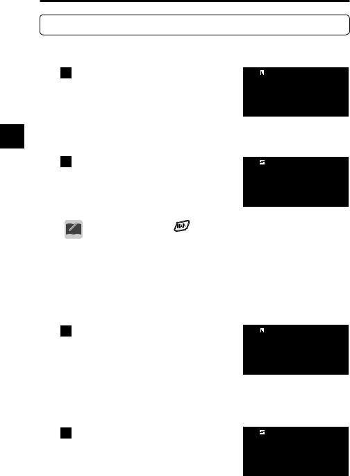
Refer to (P. 33) for the range of the receivable frequencies for each band.
1 Press the  key or
  key to select the band to operate.
When the dual-band display is selected, the frequency of the selected band is displayed in larger letters. When the
5 mono-band display is selected, only the frequency of the selected band is displayed.
2Pressing the  key or
  key again changes the band.
|
|
B S |
|
|
|
||
VFO |
|
145.000 |
|
|
|
F M |
|
VFO |
433.000 |
|
|
|
|
F M |
|
B S 
VFO
F M
VFO
F M
• |
By holding down the |
key and rotating the upper dial, you can |
|
MEMO • |
change the band quickly. |
|
|
|
indicates that the main band is currently selected for operation; |
||
 indicates that the sub band is currently selected for operation.
5-7-1 Mono-band operation
● Using the main band with mono-band operation
1 Hold down the  key (approx. one second).
The main band is displayed with the mono-band display. To return to the dualband display, repeat the same operation again.
B S
VFO 145.000
F M
●Using the sub band with mono-band operation
1Hold down the  key (approx. one second).
B S 
The sub band is displayed with the mono- |
VFO 433.000F M |
band display. |
|
To return to the dual-band display, repeat |
|
the same operation again. |
|
28

6. Operating Modes
6. Operating Modes
The DJ-X11 has three operating modes: VFO, Preset, and Memory.
VFO mode |
VFO stands for Variable Frequency Oscillator. |
|
|
|
|
You can select a desired frequency by rotating the |
|
|
|
|
dial. You can operate the receiver like a normal |
|
|
|
|
radio. |
|
|
|
Preset mode |
The audio frequencies for AM/FM radio and TV |
|
|
|
|
channels have alreday been set so that you can |
|
|
|
|
choose among them just like a conventional |
|
|
|
|
6 |
|||
|
radio. |
|
||
|
|
|
||
Memory mode |
You can program frequencies to memory |
|
||
|
||||
|
channels beforehand and call up one when you |
|
|
|
|
wish. For the frequency programming procedure, |
|
|
|
|
refer to "Memory Mode"(P. 34). |
|
|
|
|
This function is similar to the address book of a |
|
|
|
|
mobile phone. |
|
|
• For TV sound channels, only analog terrestrial broadcasting can be
received. The TV sound from digital terrestrial broadcasting cannot be CAUTION received.
•Switching between operating modes
Pressing the  key changes operating modes in the following order.
VFO
Preset |
Memory |
• The preset mode can be excluded from the operation modes.
• For details, refer to “Preset mode setting (P. 75).
MEMO
29
6. Operating Modes
6-1 Setting frequencies in VFO mode
The VFO mode is a mode displayed when you turn ON the DJ-X11 for the first time with the factory default setting. In this mode, you can select receiving frequencies by rotating the dial.
● Switching between bands
Pressing the  or
or  key will select the band.
6-2 Setting the Channel Step Frequency
A channel step refers to the interval between the frequencies which have been 6 assigned to radio communications and broadcasts. Although the typical steps have been programmed in the DJ-X11, you can change the steps as necessary.
For the procedure, refer to “Changing the Channel Step” (P. 58).
6-3 1 MHz UP/DOWN Operation
● Changing the frequency of the main band in larger increments
In VFO mode, select the main band, hold down the [FUNC] key and rotate the upper main dial. The frequency increases or decreases in units of 1 MHz.
● Changing the frequency of the sub band in larger increments
In VFO mode, select the sub band, hold down the [FUNC] key and rotate the upper sub dial. The frequency increases or decreases in units of 1 MHz.
• The 1 MHz UP/DOWN operation increases or decreases the frequency
regardless of the frequency range of the band.
MEMO • When the [FUNC] key is held down but the dial is not rotated for approximately one second, the Key-lock will be activated.
•When using the 1 MHz UP/DOWN operation, the display may sometimes jump to an unexpected frequency due to the channel step setting.
30
 Loading...