


WIDE BAND COMMUNICATION RECEIVER
DJ-X7T/E
Instruction Manual
PRI |
TONE |
BANK |
MW |
V/P/M |
SCAN |
BAND |
|
|
|
|
|
SHIFT |
PWR |
|
10M/1M |
DJ-X7
WIDE BAND COMMUNICATION RECEIVER
ALINCO, INC.

NOTICE / Compliance Information Statement
This device has been tested and found to comply with the limits for a Class B digital device, pursuant to part 15 of the FCC Rules. These limits are designed to provide reasonable protection against harmful interference in a residential installation.
This device generates, uses, and can radiate radio frequency energy and, if not installed and used in accordance with the instruction manual, may cause harmful interference to radio communications. However, there is no guarantee that interference will not occur in a particular installation. If this device does cause harmful interference to radio or television reception, which can be determined by turning the device off and on, the user is encouraged to try to correct the interference by one or more of the following measures:
•Reorient or relocate the receiving antenna.
•Increase the separation between the equipment and receiver.
•Connect the equipment to an outlet on a circuit different from that to which the receiver is connected.
•Consult the dealer or an experienced radio/TV technician for help.
Tested to Comply
With FCC Standards
FOR HOME OR OFFICE USE
Information in this document is subject to change without notice or obligation. All brand names and trademarks are the property of their respective owners. Alinco cannot be liable for pictorial or typographical inaccuracies. Some parts, options, and/or accessories are unavailable in certain areas. Changes or modifications not expressly approved by the party responsible for compliance could void the user's authority to operate the device.
Wide Band Communication Receiver DJ-X7T
This device complies with part 15 of the FCC Rules. Operation is subject to the following two conditions: (1) This device may not cause harmful interference, and (2) this device must accept any interference received, including interference that may cause undesired operation.
Conformity Information
In case the device you have purchased is marked with a CE symbol, a copy of the relative conformity certificate or document can be reviewed at http://www.alinco.com/usa.html. This device is authorized for use in all EU and EFTA member states.
MANUFACTURER: ALINCO, INC. Shin Dai Building 9F, 1-2-6, Dojimahama, Kita-ku, Osaka, 530-0004, Japan
|
Copyright © 2005 All rights reserved. No part of this document may be reproduced, copied, translated, or transcribed in any form or by any |
|
means without the prior written permission of Alinco, Inc., Osaka, Japan. |
2 |
English Edition Printed in Japan. |
|

Table of Contents
Precautions ...................................................................... |
5 |
|
Precautionary Statement .......................................................... |
5 |
|
Precautionary Statement - External Power Supply................... |
5 |
|
Request and Agreement .......................................................... |
5 |
|
Chapter 1 Features .......................................................... |
6 |
|
1.1 |
Standard Accessory List .................................................... |
6 |
Chapter 2 Accessories .................................................... |
7 |
|
2.1 |
Mounting Arrangement....................................................... |
7 |
|
■Installing & uninstalling antenna.................................. |
7 |
|
■Installing & uninstalling battery ................................... |
7 |
|
■Precaution for preventing short-circuit of battery ........ |
8 |
|
■Receiving while charging with AC adapter ................. |
9 |
|
■Low battery indicator ................................................... |
9 |
Chapter 3 Names and Functions of Parts .................... |
10 |
|
3.1 |
External View .................................................................... |
10 |
|
■Top/Front panel ......................................................... |
10 |
|
■Side panel ................................................................. |
11 |
3.2 |
Key Operations................................................................. |
12 |
3.3 |
Icons and Indicators......................................................... |
13 |
Chapter 4 Basic Operations .......................................... |
14 |
|
4.1 |
Turning Power ON ............................................................ |
14 |
4.2 |
Adjusting Volume Level.................................................... |
14 |
4.3 |
Adjusting Squelch Level................................................... |
15 |
|
■Monitor function ......................................................... |
15 |
|
■Mute function ............................................................. |
16 |
4.4 |
Operating Modes ............................................................. |
16 |
|
■Switching among modes ........................................... |
16 |
4.5 |
Frequency Settings .......................................................... |
17 |
|
■VFO mode ................................................................. |
17 |
|
■Preset mode .............................................................. |
18 |
|
■Memory mode ........................................................... |
19 |
4.6 Memory Mode .................................................................. |
19 |
|
|
■Memory types ............................................................ |
19 |
|
■Programming to memory channel ............................. |
20 |
|
■Clearing memory channel ......................................... |
21 |
|
■Programmable items to memory channels................ |
21 |
Chapter 5 Advanced Operations .................................. |
22 |
|
5.1 |
Scanning Function............................................................ |
22 |
|
■VFO scan ................................................................... |
22 |
|
■Programmed scan ..................................................... |
23 |
|
■Preset scan................................................................ |
23 |
|
■Memory scan ............................................................. |
23 |
5.2 |
Memory Skip Function...................................................... |
24 |
5.3 |
Key-lock Function............................................................. |
25 |
5.4 |
Priority Monitoring Function.............................................. |
25 |
5.5 |
Descrambling Function .................................................... |
25 |
5.6 |
Tone Squelch Function..................................................... |
26 |
5.7 |
Tone Scan Function.......................................................... |
27 |
5.8 |
Shift Function.................................................................... |
27 |
Chapter 6 Set Mode Configurations ............................. |
28 |
|
6.1 |
Set Mode Menu List.......................................................... |
28 |
6.2 |
Configuring Values/Parameters of Menu Items................ |
28 |
6.3 |
Set Mode Configurations.................................................. |
29 |
|
(1)Attenuator function setting....................................... |
29 |
|
(2)Antenna Type Switching setting .............................. |
29 |
|
(3)AM Bar-antenna setting ........................................... |
30 |
|
(4)Shortwave Bar-antenna setting................................ |
30 |
|
(5)Illumination Lamp function setting ........................... |
30 |
|
(6)Scan Type Switching setting ................................... |
31 |
|
(7)Priority Monitoring function setting .......................... |
31 |
|
(8)Auto-Power-Off function setting............................... |
31 |
|
(9)Battery-save function setting ................................... |
32 |
|
(10)Key-touch Beep function setting ........................... |
32 |
|
(11)Bell (Pager) function setting .................................. |
32 |
|
(12)Monitor/Mute function setting ................................ |
33 |
|
(13)Monitor-key Operation setting ............................... |
33 |
3

|
(14)Write-protect function setting................................. |
34 |
|
(15)Modulation Type setting ........................................ |
34 |
Chapter 7 Cable-clone and PC Connection ................. |
35 |
|
7.1 |
Cable Connection............................................................. |
35 |
7.2 |
Operation for Receiving Data (on the Slave).................... |
35 |
7.3 |
Operation for Transferring Data (on the Master) .............. |
36 |
Chapter 8 Maintenance and Reference........................ |
37 |
|
8.1 |
Troubleshooting................................................................ |
37 |
8.2 |
Resetting .......................................................................... |
38 |
|
■Factory default value ................................................. |
38 |
8.3 |
Optional Accessory List ................................................... |
38 |
8.4 |
Table of Available CTCSS Tones ..................................... |
39 |
Chapter 9 Specifications ............................................... |
40 |
|
This manual uses the following icons to explain:
 Caution
Items indicated with this icon mention precautions for use and procedures which need to be followed. Otherwise, person may be injured, or the receiver including accessories may be damaged or not operate properly.
Items indicated with this icon mention precautions for
NOTE use and procedures which need to be followed.
Memo Items indicated with this icon mention supplementary and referential information.
4

Precautions
Precautionary Statement
•Do not open the case nor touch the interior components. Tampering can damage the receiver.
•Do not place the receiver in any place where it will be subjected to direct sunlight, dust, or high temperatures.
•Keep the receiver away from TVs, tuners, or other equipment if it interferes with reception.
•Ensure that the provided antenna is securely mounted.
•Turn the power OFF immediately if the receiver should emit smoke or strange odors. Ensure that the receiver is safe, then contact the nearest Alinco Service Center.
Precautionary Statement - External Power Supply
•Use a regulated 3.7V to 6.0V DC external power supply.
•Never use any external power supply which exceeds 6.5V. Otherwise, this may cause the serious damage.
•To charge the battery or operate the receiver using AC power, use the provided AC adapter (EDC-126 or EDC-128 depending on the version). Connect the adapter to the receiver's DC-IN jack directly.
•When power is supplied from the cigarette socket of a car, use the optionally available cigar-socket DC cable (EDH-32).
•Turn the receiver's power OFF when connecting or disconnecting the cable of external power supply.
Request and Agreement
•This receiver is manufactured and shipped under strict quality control. However, in some rare instances, if questionable or doubtful points are found, please notify the store where you purchased the receiver.
•Since this is a wide band communication receiver, its internal oscillation can sometimes block a signal, or detect an internal signal (sometimes referred to as a "birdie"). These symptoms are not a malfunction.
•Specifications and information found in this document are subject to change without notice.
5

1
Features
Chapter 1 Features
•DJ-X7 is a wide band receiver and can be applied to business use.
•DJ-X7 receives AM radio with the internal bar-antenna.
•DJ-X7 receives high frequency wave (shortwave) with the internal bar-antenna.
•DJ-X7 receives FM radio with the provided earphone antenna.
•DJ-X7 features the Shift function.
•DJ-X7 features the Tone Squelch function, and it covers 39 CTCSS tones.
•DJ-X7 features the Cable-clone function.
•DJ-X7 features the PC Connection function*.
•DJ-X7 adopts Lithium ion rechargeable battery.
*The free editing software can be downloaded at our website (http://www.alinco.com). The optional PC interface-cable (ERW-4C) is required to interface your computer and the DJ-X7. Please visit our website for more details before you purchase the ERW-4C as some restrictions may apply depending on your computer conditions.
1.1 Standard Accessory List
Standard accessories may vary. Please contact your dealer for details.
• A Li-Ion rechargeable battery pack* DJ-X7T/E: EBP-58N (3.7V 600mAh)
•An AC adapter for both recharging battery and supplying power** (6.0V 0.5A)
DJ-X7T: EDC-126 (120V) DJ-X7E: EDC-128 (220V)
•An SMA whip antenna
DJ-X7T/E: EA-131
•A curl-cable earphone/antenna DJ-X7T/E: EME-25
•An antenna cap
•An instruction manual
*Hereinafter referred to as battery or battery pack.
**Hereinafter referred to as AC adapter or adapter.
6
Chapter 2 Accessories
2.1 Mounting Arrangement
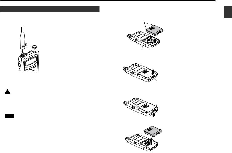
■Installing & uninstalling antenna
●Installing antenna
1.Hold the antenna at the base. 2.Attach the antenna to the
antenna connector.
3.Turn the antenna clockwise until it stops.
4.Ensure the antenna is securely installed to the receiver.
●Uninstalling antenna
Turn the antenna counterclockwise.
 Caution
When antenna connector conversion is necessary, be sure to select a proper conversion connector or cable which does not overburden the receiver. Otherwise, this may cause the damage to the receiver and/or the antenna.
NOTE Installing an excessively high performance external antenna may get worse of the receiving conditions.
■Installing & uninstalling battery
●Installing battery
Projections
1.Align the projections on the battery with the grooves on the receiver.
2.Push the battery in the direction of the arrow.
Grooves
3.Push down the latch of the battery until it clicks.
Latch
●Uninstalling battery
1.Push the latch of the battery upward.
Latch
2.Pull out the battery in the direction of the arrow.
2
Accessories
7

2
Accessories
 Caution
•Do not modify, dismantle, incinerate, or immerse the battery pack, as these practices can be dangerous.
•Do not short-circuit the terminals of the battery pack. This may cause damage to the receiver. The short-circuit may lead to overheating the battery, which causes burns.
•The battery pack should be stored in dry places where the temperature range is between -20 to 45˚C (-4 to 113˚F). Leaving the battery pack exposed in high humidity or outside the proper temperature range may cause battery liquid leakage or rust on the metal portion.
NOTE • The battery pack is not charged when shipped. It must be charged before use.
•The battery pack can be charged by plugging the AC adapter to the DC-IN jack of the receiver after mounting it to the DJ-X7.
•It takes up to 2 hours and 30 minutes (maximum) to fully charge.
•Charging should be conducted within a temperature range of 0 to 40˚C (32 to 104˚F). Otherwise, the battery won't be charged properly.
•Be sure to remove the battery pack when the receiver is not in use for a long period.
•Typically, the battery pack can be charged up to 500 times. However, it is considered consumed if the period of use significantly drops despite the battery being charged for the aforementioned charging time. When this happens, replace the old battery with a new one.
•In the interests of environmental protection, do not dispose of the battery pack improperly. Check with your local solid waste officials for details on recycling options or proper disposal in your area.
•It is not necessary to turn the power OFF of the receiver while charging. However, noise may occur during reception.
■Precaution for preventing short-circuit of battery
|
Be extra cautious when |
|
carrying the battery pack; the |
|
short-circuit will produce surge |
|
current possibly resulting in |
Terminals |
fire. |
|
DON'T carry with any |
DON'T put it in bags |
DON'T place it in the |
type of metals. (e.g. |
whose interior is |
proximity of metals or |
chains) |
plated with metal. |
conductors. (e.g. |
|
DON'T wrap with a |
nails, chains) |
|
metal plated cloth. |
|
|
|
|
Put it in a non-conductive plastic bag, or wrap it |
Protect it by |
with a non-conductive material when you carry. |
spreading a non- |
|
conductive sheet. |
8
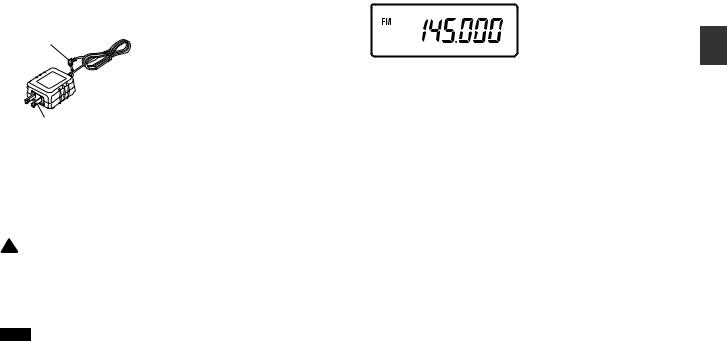
■Receiving while charging with AC adapter
●Charging battery
AC adapter plug
1.Install the battery pack to the receiver.
2.Plug the AC adapter to the DC-IN jack of the receiver.
3.Plug the power plug to an outlet.
Power plug
(EDC-128 has different shape.)
Regardless of whether the power ON or OFF of the receiver, it will start charging.
When the receiver is OFF state, the low battery indicator shown below blinks and the RX lamp illuminates during charge. Once it is fully charged, the lamp will go off.
 Caution
•Never charge batteries of other manufacturers. Never plug the provided AC adapter to other devices, either.
•If you should short-circuit the terminals with metal objects and the like, it may cause damage to both the receiver and the battery.
NOTE • Be sure to connect the AC adapter after mounting the battery pack to the receiver. Otherwise, the battery
won't be charged.
•Be sure to unplug the AC adapter when it is not in use.
•The required charging time depends on the condition of the battery pack.
•The battery won't be charged if the voltage from an outlet is extremely low.
■Low battery indicator


 Low battery indicator
Indicates the charge level is low.
•Battery consumption level may change depending on the surrounding temperature or the conditions of use.
•Charge the battery when the indicator appears.
•This is not an indicator for battery life remaining.
2
Accessories
9
3
Parts of Functions and Names
Chapter 3 Names and Functions of Parts
3.1 External View
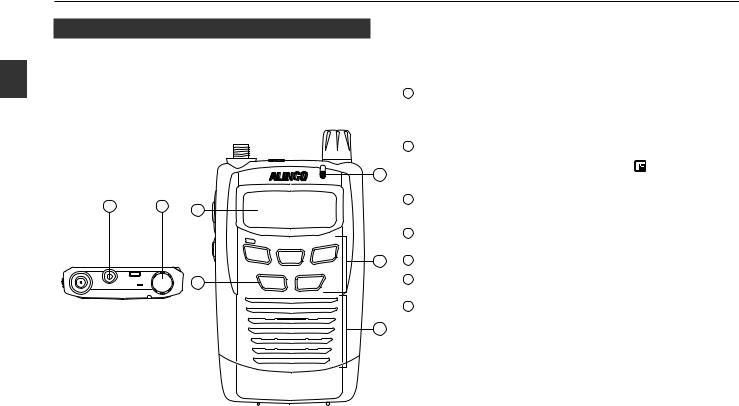
■Top/Front panel
1 |
2 |
7 |
|
|
PRI MW
V/P/M
TONE
SCAN
BANK BAND
|
|
6 |
|
SHIFT |
|
PUSH |
PWR |
10M/1M |
|
EAR |
VOL/SQL |
|||
SET |
|
|
|
|
Item |
Description |
|
|
|
|
|
|
|
1 |
Earphone jack |
This is for plugging an earphone or an external |
|
|
speaker (8Ω) with 2.5ø stereo plug. |
|||
|
|
|
||
|
|
|
Rotate this dial to change frequency and various |
|
|
|
|
settings. |
|
|
2 |
Dial |
Press this dial to adjust the volume and squelch |
|
|
levels. |
|
||
|
|
|
|
|
3 |
|
|
Pressing it down while the |
icon appears |
|
|
switches to the Set mode. (P.28) |
||
|
|
|
||
|
3 |
RX lamp |
It illuminates green while it receives signals or |
|
|
the squelch opens. |
|
||
|
|
|
|
|
|
|
|
Use this keypad to change mode and various |
|
|
4 |
Keypad |
settings. |
|
|
|
|
See on P.12 for more information. |
|
4 |
5 |
Speaker |
A thin speaker is built in. |
|
|
6 |
Power key |
Holding this key for 1 second turns the power |
|
|
ON/OFF of the receiver. |
|
||
|
|
|
|
|
|
7 |
LCD |
It displays frequency and other information. |
|
|
See on P.13 for more information. |
|||
|
|
|
||
5 |
|
|
|
|
DJ-X7
WIDE BAND COMMUNICATION RECEIVER
10
■Side panel
8
F |
LOCK |
9
10
ST SK
MONI
|
|
|
|
Item |
Description |
|
|
|
|
|
|
|
|
|
|
|
8 |
Antenna |
Install the included whip antenna or an external |
|
|
connector |
antenna. |
|
|||
|
|
|
|
|
||
|
|
|
|
|
(Hereinafter referred to as [F] key.) |
|
|
|
|
|
Function key |
Use this key in combination with other keys to |
|
|
|
|
9 |
access various functions of the receiver. |
||
|
(LOCK) |
|||||
|
|
|
|
Holding this key for 1 second activates the Key- |
||
|
|
|
|
|
||
|
|
|
|
|
lock function. |
|
|
|
|
|
|
(Hereinafter referred to as [MONI] key.) |
|
|
|
|
|
|
When this key is pressed, squelch opens so that |
|
|
|
|
10 |
Monitor key |
you may receive weaker signals better. |
|
|
(ST/SK) |
TSQ becomes deactivated also. |
||||
|
|
|
|
|||
|
|
11 |
|
|
Pressing it down while the |
icon appears |
|
|
|
|
changes tuning steps. |
|
|
|
|
|
||||
|
|
|
|
|
This is for plugging an external power supply. |
|
|
|
|
|
|
||
|
|
|
|
|
Connect the included AC adapter or an optional |
|
|
|
|
|
|
cigarette lighter cable to operate without |
|
|
|
|
|
|
battery. |
|
|
|
|
11 |
DC-IN jack |
When you install the provided battery, you can |
|
|
|
|
charge it by connecting the adapter or the |
|||
|
|
|
|
|
||
|
|
|
|
|
cable. |
|
|
|
|
|
|
(Depending on the receiving frequency, noise |
|
|
|
|
|
|
may occur when you use the receiver with the |
|
|
|
|
|
|
cable.) |
|
3
Parts of Functions and Names
11

3
Parts of Functions and Names
3.2 Key Operations
Dial
[F] key
PRI MW
V/P/M
TONE
SCAN
BANK BAND
|
SHIFT |
PWR |
10M/1M |
Key |
Independent Operation |
While |
is ON |
Holding for 1 Sec |
Dial Operation with Holding |
V/P/M |
Switch among the |
Program to memory channels |
Perform the Priority Monitoring |
|
|
VFO/Preset/Memory mode (P.16) |
(P.20) |
|
function (P.25) |
|
|
|
|
|
|||
SCAN |
Start scanning (P.22-24, 25-27) |
Switch to the Tone Squelch |
|
Switch among the scanning |
|
|
setting (P.26) |
|
|
modes (P.22-24) |
|
|
|
|
|
||
BAND |
Switch among bands (P.17) |
Switch among banks |
Switch to the setting of bank |
|
|
|
|
|
links |
|
|
|
|
|
|
|
|
PWR |
|
|
|
Turn power ON/OFF (P.14) |
|
|
Perform the Shift function (P.27) |
Switch to the Shift setting (P.27) |
|
|
|
10M/1M |
Switch between 10MHz and |
|
|
|
|
|
1MHz up/down (P.18) |
|
|
|
|
F |
Switch among functions |
|
|
Set and release the Key-lock |
|
|
|
|
function (P.25) |
|
|
|
|
|
|
|
|
|
Adjust volume, squelch, and |
Switch to the Set mode (P.28) |
|
|
|
Dial |
other parameters/values |
|
|
|
|
|
(P.14-15, 28) |
|
|
|
|
12

3.3 Icons and Indicators
1 |
2 |
3 |
4 |
5 |
6 |
7 |
8 |
18
9
17
|
16 |
15 |
14 |
13 |
12 |
|
1 |
Appears when the [F] key is pressed. |
|
|
|
|
|
2 |
Appears while the keypad is locked. |
|
|
|
|
|
3 |
Appears while the Attenuator function is ON. |
|
|
|||
4 |
Indicates the shift direction. |
|
|
|
|
|
5 |
T appears during the tone squelch operation. |
|
|
|||
SQ appears during the tone signal detection operation. |
||||||
|
||||||
6 |
Appears while the Auto-Power-Off function is ON. |
|
||||
7 |
Appears while the Battery-save function is ON. |
|
||||
8 |
Appears only when the remaining battery level is low. |
|||||
9 |
Displays frequency and values of the various settings. |
|||||
11 10
11
12
13
14
15
16
17
18
Blinks during various types of scanning operations. Disappears during the memory skip operation.
Appears when the receiver squelch opens.
Appears while the Bell function is ON.
Blinks during the descrambling operation.
Appears when you link banks in the linked banks scan of the DJ-X7's memory scan.
Appears while the Priority Monitoring function is ON.
Displays the memory channel number, the set menu number, and other various settings.
Indicates a modulation type (AM/FM/WFM).
10 |
Indicates strength of the receiving signals. |
* The unexplained icon is not used on this receiver. |
|
3
Parts of Functions and Names
13
 Loading...