


VHF FM TRANSCEIVER
DJ-V17T/E/R/TFH
Instruction Manual
Thank you for purchasing your new Alinco transceiver. This instruction manual contains important safety and operating instructions. Please read this manual carefully before using the product and keep it for future reference.
ALINCO, INC.

NOTICE / Compliance Information Statement
NOTICE / Compliance Information Statement
This equipment has been tested and found to comply with the limits for a Class B digital device, pursuant to part 15 of the FCC Rules.
These limits are designed to provide reasonable protection against harmful interference in a residential installation.
This equipment generates, uses, and can radiate radio frequency energy and, if not installed and used in accordance with the instruction manual, may cause harmful interference to radio communications. However, there is no guarantee that interference will not occur in a particular installation. If this equipment does cause harmful interference to radio or television reception, which can be determined by turning the equipment off and on, the user is encouraged to try to correct the interference by one or more of the following measures:
•Reorient or relocate the receiving antenna.
•Increase the separation between the equipment and receiver.
•Connect the equipment into an outlet on a circuit different from that to which the receiver is connected.
•Consult the dealer or an experienced radio/TV technician for help.
Tested to Comply
With FCC Standards
FOR HOME OR OFFICE USE
Information in this document is subject to change without notice or obligation. All brand names and trademarks are the property of their respective owners. Alinco cannot be liable for pictorial or typographical inaccuracies. Some parts, options and/or accessories are unavailable in certain areas. Changes or modifications not expressly approved by the party responsible for compliance could void the user's authority to operate the equipment.
VHF FM Transceiver DJ-V17T
This device complies with Part 15 of the FCC Rules. Operation is subject to the following two conditions: (1) This device may not cause harmful interference, and (2) this device must accept any interference received, including interference that may cause undesired operation.
Manufacturer:
ALINCO, INC.
Shin-Dai building 9th Floor 2-6, 1-Chome
Dojimahama, Kita-ku, Osaka 530-0004 JAPAN
2

NOTICE / Compliance Information Statement
Conformity Information
In case the unit you have purchased is marked with a CE symbol, a copy of relative conformity certificate or document can be reviewed at http://www.alinco.com/usa.html.
DJ-V17E: VHF FM Transceiver 144.000~145.995MHz CE 0336 
This device is authorized for use in all EU and EFTA member states. An operator's license is required for this device.
Copyright © All rights reserved. No part of this document may be reproduced, copied, translated or transcribed in any form or by any means without the prior written permission of Alinco. Inc., Osaka, Japan, English Edition Printed in Japan.
3

Warning
Warning
To prevent any hazard during operation of Alinco's radio product, in this manual and on the product you may find symbols shown below. Please read and understand the meanings of these symbols before starting to use the product.
d Danger |
This symbol is intended to alert the user to an immediate danger that |
may cause loss of life and property if the user disregards the warning. |
|
|
|
d Alert |
This symbol is intended to alert the user to a possible hazard that |
may cause loss of life and property if the user disregards the warning. |
|
|
|
d Caution |
This symbol is intended to alert the user to a possible hazard that may |
cause loss of property or injure the user if the warning is disregarded. |
|
|
|
dAlert symbol. An explanation is given.
aWarning symbol. An explanation is given.
mInstruction symbol. An explanation is given.
dAlert
■Environment and condition of use
jDo not drive while handling the radio for your safety. It is recommended that you check local traffic regulations regarding the use of radio equipment while driving. Some countries prohibit the operation of transceiver while driving.
jDo not use this product in close proximity to other electronic devices, especially medical ones. It may cause interference to those devices.
aKeep the radio out of the reach of children.
jIn case a liquid leaks from the product, do not touch it. It may damage your skin. Rinse with plenty of cold water if the liquid contacted your skin.
jNever operate this product in facilities where radio products are prohibited for use such as aboard aircraft, in airports, in ports, within or near the operating area of business wireless stations or their relay stations.
jUse of this product may be prohibited or illegal outside of your country. Be informed in advance when you travel.
aThe manufacturer declines any responsibilities against loss of life and/or property due to a failure of this product when used to perform important tasks like life-guarding, surveillance, and rescue.
4

Warning
jDo not use multiple radios in very close proximity. It may cause interference and/or damage to the product(s).
aRisk of explosion if battery is replaced with an incorrect type.
Dispose of, or recycle used batteries according to your local regulations.
aThe manufacturer declines any responsibilities against loss of life and property due to a failure of this product when used with or as a part of a device made by third parties.
aUse of third party accessory may result in damage to this product. It will void our warranty for repair.
■Handling this product
aBe sure to reduce the audio output level to minimum before using an earphone or a headset. Excessive audio may damage hearing.
mDo not open the unit without permission or instruction from the manufacturer. Unauthorized modification or repair may result in electric shock, fire and/or malfunction.
lDo not operate this product in a wet place such as shower room. It may result in electric shock, fire and/or malfunction.
jDo not place the product in a container carrying conductive materials, such as water or metal in close proximity to the product. A short-circuit to the product may result in electric shock, fire and/or malfunction.
■About chargers
jDo not use adapters other than the specified voltage. It may result in electric shock, fire and/or malfunction.
jDo not plug multiple devices using an adapter into a single wall outlet. It may result in overheating and/or fire.
jDo not handle adapter with a wet hand. It may result in electric shock.
aSecurely plug the adapter into the wall outlet. Insecure installation may result in short-circuit, electronic shock and/or fire.
jDo not use the adapter if the plug or socket contacts are dirty. Overheating and/or short-circuiting may result in fire, electric shock and/or damage to the product.
■About power supply
jUse only appropriate, reliable power supply of correct voltage and capacity.
jDo not connect cables in reverse polarity. It may result in electric shock, fire and/or malfunction.
jDo not plug multiple devices including the power supply into a single wall outlet. It may result in overheating and/or fire.
5

Warning
jDo not handle a power supply with a wet hand. It may result in electric shock.
aSecurely plug the power supply to the wall outlet. Insecure installation may result in short-circuiting, electronic shock and/or fire.
jDo not plug the power supply into the wall socket if the contacts are dirty. Short-circuit and/or overheating may result in fire, electric shock and/or damage to the product.
jDo not modify or remove fuse-assembly from the DC cable. It may result in fire, electric shock and/or damage to the product.
■Cigar-lighter cable
jDo not use the cable at any other than the specified voltage. It may result in electric shock, fire and/or malfunction.
jDo not handle cigar cable with a wet hand. It may result in electric shock.
■In case of emergency
In case of the following situation(s), please turn off the product, switch off the source of power, then remove or unplug the power-cord. Please contact your local dealer of this product for service and assistance. Do not use the product until the trouble is resolved. Do not try to troubleshoot the problem by yourself.
• When a strange sound, smoke and/or strange odor comes out of the product.
• When the product is dropped or the case is broken or cracked.
• When a liquid penetrated inside.
• When a power cord (including DC cables, AC cables and adapters) is damaged.
aFor your safety, turn off then remove all related AC lines to the product and its accessories from the wall outlet if a thunderstorm is likely.
■Maintenance
mDo not open the unit and its accessories. Please consult with your local dealer of this product for service and assistance.
6

Warning
dCaution
■Environment and condition of use
jDo not use the product in proximity to a TV or a radio. It may cause interference or receive interference.
jDo not install in a humid, dusty or insufficiently ventilated place. It may result in electric shock, fire and/or malfunction.
jDo not install in an unstable or vibrating position. It may result in electric shock, fire and/or malfunction when/if the product falls to the ground.
jDo not install the product in proximity to a source of heat and humidity such as a heater or a stove. Avoid placing the unit in direct sunlight.
jBe cautious of a dew formation. Please completely dry the product before use when it happens.
■About transceiver
aBe cautious of the whip antenna when carried in your shirt-pocket etc. It may make contact with your eye and cause injury.
jDo not connect devices other than specified ones to the jacks and ports on the product. It may result in damage to the devices.
aTurn off and remove the power source (AC cable, DC cable, battery, cigar cable, charger adapter etc.) from the product when the product is not in use for extended period of time or in case of maintenance.
jNever pull the cord alone when you unplug AC cable form the wall outlet.
aUse a clean, dry cloth to wipe off dirt and condensation from the surface of the product. Never use thinner or benzene for cleaning.
■About power supply
aUse only reliable power supply of specific DC output range and be mindful of the polarity of the cable and DC-jack.
aAlways turn off the power supply when connecting or disconnecting the cables.
aWhen using an external antenna, make sure that the antenna ground is not common with the ground of the power supply.
aEuropean users: When a unit is powered from an external DC power source (adapter, power supply, cigar-plug etc.), make sure that this power supply has approval to the level of IEC/EN 60950.
7


Introduction
Introduction
Thank you very much for purchasing this excellent Alinco transceiver. Our products are ranked among the finest in the world. This radio has been manufactured with state of the art technology and it has been tested carefully at our factory. It is designed to operate to your satisfaction for many years under normal use.
PLEASE READ THIS MANUAL COMPLETELY TO LEARN ALL THE FUNCTIONS THE PRODUCT OFFERS. WE MADE EVERY ATTEMPT TO WRITE THIS MANUAL TO BE AS COMPREHENSIVE AND EASY TO UNDERSTAND AS POSSIBLE. IT IS IMPORTANT TO NOTE THAT SOME OF THE OPERATIONS MAY BE EXPLAINED IN RELATION TO INFORMATION IN PREVIOUS CHAPTERS. BY READING JUST ONE PART OF THE MANUAL, YOU RISK NOT UNDERSTANDING THE COMPLETE EXPLANATION OF THE FUNCTION.
9

Contents
Contents
NOTICE / Compliance Information Statement................................................ |
3 |
||
Warning............................................................................................................... |
|
5 |
|
Introduction ........................................................................................................ |
9 |
||
Contents ........................................................................................................... |
|
10 |
|
1.Features ......................................................................................................... |
|
13 |
|
1.1 |
Accessories ......................................................................................................... |
13 |
|
2.Accessories ................................................................................................... |
14 |
||
2.1 |
Installations......................................................................................................... |
14 |
|
|
2.1.1 |
Antenna ...................................................................................................... |
14 |
|
2.1.2 |
Hand Strap.................................................................................................. |
14 |
|
2.1.3 |
Belt Clip ..................................................................................................... |
14 |
|
2.1.4 |
Battery Pack ............................................................................................... |
15 |
|
2.1.5 Prevent Short Circuiting the Battery Pack ................................................. |
17 |
|
|
2.1.6 Dry Cell Case (optional)............................................................................. |
18 |
|
|
2.1.7 |
Battery-Level Icon...................................................................................... |
18 |
3.Names and Operations of Parts .................................................................. |
19 |
||
3.1 |
Names and Operations of Keys and Ports........................................................... |
19 |
|
3.2 |
Keypad ................................................................................................................ |
21 |
|
3.3 |
Display (LCD) .................................................................................................... |
22 |
|
4.Basic Operation ............................................................................................ |
23 |
||
4.1 |
Turning On the Power......................................................................................... |
23 |
|
4.2 |
Adjusting the Audio Output (Volume) ............................................................... |
23 |
|
4.3 |
Adjusting the Squelch......................................................................................... |
23 |
|
4.4 |
Setting the Frequency in the VFO Mode ............................................................ |
24 |
|
|
4.4.1 |
Setting the Frequency................................................................................. |
24 |
|
4.4.2 Setting the Tuning Step .............................................................................. |
25 |
|
|
4.4.3 Shift Direction and Offset Frequency Settings........................................... |
25 |
|
4.5 |
Memory Mode .................................................................................................... |
26 |
|
|
4.5.1 How to Program Memory Channel(s) ........................................................ |
26 |
|
|
4.5.2 Recalling a Memory Channel..................................................................... |
27 |
|
|
4.5.3 Deleting a Memory Channel ...................................................................... |
27 |
|
|
4.5.4 Programming a Repeater-Access Function Setting.................................... |
27 |
|
|
4.5.5 Programmable Parameters in Memory Channels....................................... |
28 |
|
4.6 |
Call-Channel Mode............................................................................................. |
28 |
|
10
|
|
|
Contents |
|
|
|
|
4.7 |
Receiving ............................................................................................................ |
29 |
|
|
4.7.1 |
Monitor Function........................................................................................ |
29 |
4.8 |
Transmitting ....................................................................................................... |
30 |
|
|
4.8.1 Selecting the Output Level ......................................................................... |
30 |
|
5.Useful Functions ........................................................................................... |
31 |
||
5.1 |
Scan Modes......................................................................................................... |
31 |
|
|
5.1.1 |
VFO-Scan................................................................................................... |
31 |
|
5.1.2 |
Memory-Scan ............................................................................................. |
31 |
|
5.1.3 |
Setting Skip Channels ................................................................................ |
32 |
5.2 |
Keylock............................................................................................................... |
32 |
|
5.3 |
Tone-Burst .......................................................................................................... |
32 |
|
5.4 |
Naming Memory Channels ................................................................................. |
33 |
|
|
5.4.1 |
Setting Name-Tag....................................................................................... |
33 |
|
5.4.2 Using the Channel Name Function ............................................................ |
33 |
|
5.5 |
Auto-Power-Off (APO) ...................................................................................... |
34 |
|
|
5.5.1 |
Setting APO................................................................................................ |
34 |
|
5.5.2 |
APO Operation ........................................................................................... |
34 |
5.6 |
Time-Out-Timer (TOT) ...................................................................................... |
35 |
|
|
5.6.1 |
Setting TOT................................................................................................ |
35 |
|
5.6.2 |
TOT Operation ........................................................................................... |
35 |
5.7 |
Lamp .................................................................................................................. |
35 |
|
6.Selective Calling............................................................................................ |
36 |
||
■Selective Calling Operations ................................................................................... |
36 |
||
6.1 |
Tone Squelch (TSQ) ........................................................................................... |
36 |
|
|
6.1.1 Setting the Tone Squelch............................................................................ |
36 |
|
|
6.1.2 Switching Off the Tone Squelch ................................................................ |
37 |
|
|
6.1.3 To Differentiate the ENC/DEC Tones ....................................................... |
37 |
|
|
6.1.4 |
Tone Squelch Operation............................................................................. |
37 |
6.2 |
DCS |
.................................................................................................................... |
37 |
|
6.2.1 |
Setting the DCS .......................................................................................... |
37 |
|
6.2.2 Changing the DCS Code ............................................................................ |
38 |
|
|
6.2.3 |
Switching Off DCS .................................................................................... |
38 |
|
6.2.4 |
DCS Operation ........................................................................................... |
38 |
|
6.2.5 DET Mode in DCS Operation .................................................................... |
38 |
|
6.3 |
DTMF Tone Encoding........................................................................................ |
39 |
|
6.4 |
Auto Dialer ......................................................................................................... |
40 |
|
|
6.4.1 Setting the Auto Dialer............................................................................... |
40 |
|
|
6.4.2 Generating the Auto Dialer Codes ............................................................. |
40 |
|
|
6.4.3 |
Redial.......................................................................................................... |
41 |
11

Contents
7.Special Functions.......................................................................................... |
42 |
|
7.1 |
ATT (Attenuator) ................................................................................................ |
42 |
7.2 |
Battery Refresh ................................................................................................... |
42 |
7.3 |
Repeater-Access.................................................................................................. |
43 |
8.Set Mode........................................................................................................ |
44 |
||
8.1 |
Set Mode Operation ............................................................................................ |
44 |
|
8.2 Entering the Set Mode ........................................................................................ |
44 |
||
8.3 |
Available Parameters .......................................................................................... |
45 |
|
|
8.3.1 |
Menu 1 Battery Save (BS) Function .......................................................... |
45 |
|
8.3.2 |
Menu 2 Timer/Busy Scan Setting .............................................................. |
45 |
|
8.3.3 |
Menu 3 Beep Function ............................................................................... |
45 |
|
8.3.4 |
Menu 4 Tone-Burst Frequency Setting ...................................................... |
45 |
|
8.3.5 |
Menu 5 Clock Shift Setting ........................................................................ |
46 |
|
8.3.6 |
Menu 6 Busy Channel Lockout Setting ..................................................... |
46 |
|
8.3.7 |
Menu 7 TOT Penalty Time ........................................................................ |
47 |
|
8.3.8 |
Menu 8 DTMF WAIT Time....................................................................... |
47 |
|
8.3.9 |
Menu 9 DTMF Burst/Pause Time .............................................................. |
47 |
|
8.3.10 |
Menu 10 DTMF First Digit Burst Time..................................................... |
48 |
|
8.3.11 |
Menu 11 Battery Charge Function ............................................................. |
48 |
|
8.3.12 |
Menu 12 Battery Type Setting ................................................................... |
49 |
9.Cloning and Packet Operation .................................................................... |
50 |
||
9.1 |
Cloning................................................................................................................ |
50 |
|
|
9.1.1 |
Cable Connection ....................................................................................... |
50 |
|
9.1.2 |
Master/Slave Units ..................................................................................... |
50 |
|
9.1.3 |
Master Unit Operation................................................................................ |
51 |
|
9.1.4 |
Slave Unit Operation .................................................................................. |
51 |
9.2 |
Packet Operation................................................................................................. |
52 |
|
|
9.2.1 |
Packet Operation Connections ................................................................... |
52 |
10.Maintenance and Reference...................................................................... |
53 |
||
10.1 |
Troubleshooting .................................................................................................. |
53 |
|
10.2 |
Resetting ............................................................................................................. |
54 |
|
10.3 |
Options................................................................................................................ |
55 |
|
10.3.1 |
Microphone/Speaker Cable (EDS-10)........................................................ |
56 |
|
10.3.2 |
Battery Packs.............................................................................................. |
56 |
|
10.3.3 |
Using the Chargers ..................................................................................... |
57 |
|
11.Specifications ............................................................................................. |
63 |
||
12

|
1.Features |
|
|
|
|
1. Features |
1 |
|
This transceiver has the following main features. |
||
■High-grade waterproof compatible to IPX7 * (submersible 1m/3feet for 30min.) and rugged body
■39 CTCSS tone squelch
■104 DCS digital code squelch
■Time-Out-Timer
■Alphanumeric display
■4 tone-burst tones (1750, 2100, 1000, 1450Hz)
■9 auto dial memories easily accessed from the DTMF keypad with redial function
■Direct frequency entry from the DTMF keypad
■A quick "Repeater-Access" function
■Refresh function for rechargeable battery reconditioning
■Cable Cloning
*The factory guarantees this grade for 1 year when all the jack-covers are properly and securely closed.
1.1 Accessories
•Ni-MH battery pack EBP-65 (7.2V 700mAh)
•EDC-146 (AC 120V) wall charger (T version)
•EDC-147 (AC 230V) wall charger (E/TFH/R version)
•Flexible whip antenna EA0141 (T/E version)
•Flexible whip antenna EA0142 (TFH/R version)
•Belt clip
•Hand strap
•Instruction manual
*Accessories may differ depending on the version you have purchased.
Please contact your local dealer for details of standard accessories and the warrantypolicy.
13

2.Accessories
2.Accessories
2.1 Installations
2 |
2.1.1 Antenna |
|
■ Attaching the Antenna |
||
|
1. |
Hold the antenna by its base. |
|
2. |
Align the grooves at the base of the antenna with |
|
|
the protrusions on the antenna connector. |
|
3. |
Slide the antenna down and turn it clockwise until |
|
|
it stops. |
|
4. |
Confirm that the antenna is securely connected. |
NOTE:
This antenna has been designed very flexible. It is softer than conventional ones but not a defect.
■Removing the Antenna
Turn the antenna counter-clockwise to disconnect the antenna.
2.1.2Hand Strap
Attach the hand strap as shown. There are two ways to attach it.
Hand strap
2.1.3Belt Clip
■Attaching the Belt Clip
1. Put the belt clip on the back of the unit, and turn
the screw clockwise until it stops. |
Belt clip |
|
2. Confirm that the belt clip is securely attached.
■Removing the Belt Clip
Turn the screw counter-clockwise to remove the belt clip.
14

2.Accessories
2.1.4 Battery Pack
For the specifications and the charging procedures, please refer to "Battery Packs"(page 56) and "Using the Chargers"(page 57).
■Attaching the Battery Pack
Align the catches on the battery pack with the grooves on the unit, and close the latch until it clicks.
2 |
Catch |
Latch |
Groove |
■Removing the Battery Pack
Push the latch in the direction of the arrow, and pull out the battery pack.
 Caution
•The battery pack isn't fully charged when shipped. It must be charged before use.
•Charging should be conducted in a temperature range of 0ºC to +40ºC (+32ºF to +104ºF).
•Don't modify, dismantle, incinerate or immerse the battery pack in the water as this can be dangerous.
•Never short-circuit the battery pack terminals, as this can cause damage to the equipment or lead to heating of the battery which may cause burns.
•Unnecessary prolonged charging (overcharging) can deteriorate battery performance.
•The battery pack should be stored in a dry place where temperature is in -10ºC to +45ºC (-14ºF to +113ºF) range. Temperatures outside this range can cause the battery liquid to leak. Exposure to prolonged high humidity can cause corrosion of metal components.
•Battery-packs are a consuming part. When its operating time becomes considerably short after a normal charge, please consider that the pack is exhausted and replace it with a new one.
•The battery pack is recyclable. Check with your local waste officials for details on recycling options or proper disposal in your area.
15
2.Accessories
 Caution
•Li-ion battery packs can't be charged using DC-jack on the unit (Only NiMH battery packs can be charged).
•Risk of explosion, generation of heat or leak of chemicals inside if the
2 |
battery is replaced by an incorrect type. Use always the recommended |
types of batteries in this manual only. |
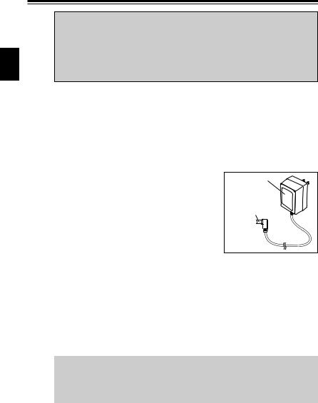
■Charging the Battery Pack Using DC-Jack on the Unit
The unit can charge the EBP-65 and EBP-66 optional Ni-MH battery packs by supplying DC power through the DC-jack on the unit using EDC-146/147/148 wall chargers or an optional DC power supply (DC 12V~DC 16V, 1A or more: IEC/EN 60950 compliant).
1.Attach the battery pack by referring to "Battery Pack" (page 15).
2.Connect the AC adapter plug to the DC-jack on the
AC adapter*
unit then connect the charger's adapter to the wall outlet.
* AC adapter may look different.
AC adapter plug
3. Turn on the unit and set the battery charge parameters. Please refer to "Set Mode" (page 44) then:
* "Battery Charge Function" (page 48) Select CHG-ON.
* "Battery Type Setting" (page 49) Select BATT-NI.
4.After completing the settings, a flashing  appears on the display. Make sure the icon is
flashing then turn off the unit. It takes about 10 hours/30hours for EBP-65/66 respectively to complete the charge.
IMPORTANT NOTE:
While this function is activated, without attaching a battery pack or the remaining battery level is below the usable range, the unit turns on by just connecting the DC source such as an adapter or a DC cable (without operating the power key).
16
2.Accessories
NOTE: |
|
• Please read the general safety instructions included in the optional accessories |
|
to correctly and safely use them. |
|
• EDC-146/147/148 can't be used as the adapter for operation. These adapters |
|
are for charging purposes only. |
2 |
• Chargers can't perform the correct charge when the AC voltage is unstable. |
• flashes even EBP-65/66 aren't attached. To avoid short-circuit, never activate this function when the pack isn't attached to the unit.
•Li-ion battery packs can't be charged in this way.
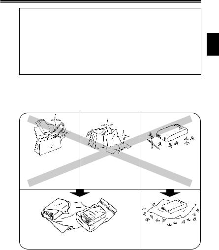
2.1.5Prevent Short Circuiting the Battery Pack
Be extra cautious when carrying the rechargeable battery pack; short circuiting will produce surge current possibly resulting in fire.
DON'T carry with metals of any type, e.g. chains.
DON'T carry the battery pack inside bags made of conductive materials.
DON'T place in the proximity of metals or conductives, e.g. nails, chains.
Do enclose inside a non-conductive enclosure. (bags or handkerchief made only of non-conductive material)
Do protect by spreading a non-conductive sheet on a flat surface.
17
2.Accessories
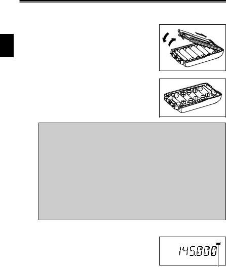
2.1.6 Dry Cell Case (optional)
An EDH-34 is available for operation with using AA cells. |
|
||
Lift up the catches on the top of the case to |
|
|
|
remove the cover. |
|
||
|
|||
2 |
|
|
Place 6 AA cells, then close the cover in order of then . Be sure that the cover is securely closed.
 Caution
•This dry cell case isn't water-proof.
•Be extra-cautious to the polarity of the cells (+)/(-). Misplacing cells may result in leak, fire or explosion.
•Use new batteries of the same type and brand when placing them.
•Use of rechargeable cells is prohibited and the manufacturer declines any responsibilities for damages/injuries that may cause to the users and their properties.
•It is recommended to clean the battery contacting terminals with a clean dry cloth from time to time.
•Risk of explosion if batteries are replaced by an incorrect type.
•Batteries are recyclable. Please check the local rules for proper recycle/disposal in your area.
2.1.7Battery-Level Icon
During the operation, a black battery icon indicates that the battery-level is in usable range. When it turns to empty, please charge the pack or replace the cells with new ones.
Battery-level icon
 The battery is in usable condition.
  Battery-level is low.
Replace or charge the pack.
18

3.Names and Operations of Parts
3.Names and Operations of Parts
3.1 Names and Operations of Keys and Ports
■Top and Front

 3
3


|
|
|
Dial |
Rotate the dial to select the frequency of operation, memory |
|
|
channel, offset frequency, tone frequency, DCS code, Set mode |
|
|
settings, and the characters for name-tags. Rotating the dial |
|
|
while pressing the FUNC key increases or decreases the |
|
|
frequency in 1MHz order. |
|
Microphone/Spe |
For an optional speaker/Mic connection. Securely close the |
|
aker jack |
cover for water-proof while the accessory isn't in use. |
|
TX/RX lamp |
Lights green when the squelch is unmuted. Lights red during |
|
|
transmission. |
|
Speaker |
A speaker is built in. |
|
Power key |
Press the power key down for approximately one second to turn |
|
|
on/off the unit. |
|
Microphone |
Speak into the microphone from a distance of about 5cm (2"). |
|
Display (LCD) |
Refer to "Display" (page 22). |
|
Keypad |
Refer to "Keypad" (page 21). |
19
3.Names and Operations of Parts
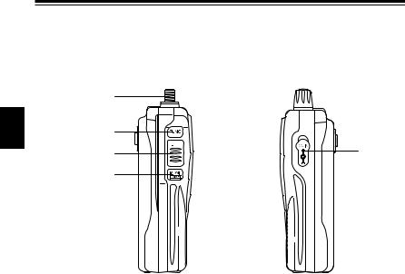
■ Side
3
|
|
|
|
|
Antenna side |
Dial side |
|
|
|
||
|
SMA Antenna |
Attach the whip antenna. If you plan to use an optional antenna, |
|
|
Connector |
select one that is tuned to the operating frequency. |
|
|
FUNC key |
The FUNC key is used in combination with the other keys to |
|
|
|
access the various functions of the unit. To enter the Set mode |
|
|
|
to set operating parameters, press the FUNC key continuously |
|
|
|
for about 2 seconds. |
|
|
PTT key |
Press the PTT key to transmit, release to receive. |
|
|
MONI key |
When the MONI key is pressed, the squelch unmutes regardless |
|
|
|
of the TSQ/DCS setting. Pressing the MONI key after pressing |
|
|
|
the FUNC key illuminates display for about 5 seconds. Pressing |
|
|
|
the MONI key while pressing the PTT key transmits a tone-burst |
|
|
|
signal. |
|
|
DC-IN jack |
Connect an external power source of DC 7.0V~DC 16.0V at 2A |
|
|
|
or more. An optional EDC-36 cigar-cable is available for mobile |
|
|
|
operation. EBP-65/66 packs can be charged using this jack |
|
|
|
(page 16). |
|
20
 Loading...