


VHF FM Mobile Transceiver
DR-135T 


Instruction Manual
Thank you for purchasing your new Alinco transceiver.
This instruction manual contains important safety and operating instructions. Please read this manual carefully before using the product and keep it for future reference.

NOTICE / Compliance Information Statement
This equipment has been tested and found to comply with the limits for a Class B digital device, pursuant to part 15 of the FCC Rules.
These limits are designed to provide reasonable protection against harmful interference in a residential installation. This equipment generates, uses, and can radiate radio frequency energy and, if not installed and used in accordance with the instruction manual, may cause harmful interference to radio communications. However, there is no guarantee that interference will not occur in a particular installation. If this equipment does cause harmful interference to radio or television reception, which can be determined by turning the equipment off and on, the user is encouraged to try to correct the interference by one or more of the following measures:
•Reorient or relocate the receiving antenna.
•Increase the separation between the equipment and receiver.
•Connect the equipment into an outlet on a circuit different from that to which the receiver is connected.
•Consult the dealer or an experienced radio/TV technician for help.
Tested to Comply
With FCC Standards
FOR HOME OR OFFICE USE
Information in this document is subject to change without notice or obligation. All brand names and trademarks are the property of their respective owners. Alinco cannot be liable for pictorial or typographical inaccuracies. Some parts, options and/or accessories are unavailable in certain areas. Changes or modifications not expressly approved by the party responsible for compliance could void the user's authority to operate the equipment.
VHF FM Transceiver DR-135TMK
This device complies with Part 15 of the FCC Rules. Operation is subject to the following two conditions:
(1) This device may not cause harmful interference, and (2) this device must accept any interference received, including interference that may cause undesired operation.
U.S. Representative:
ATOC Amateur Distributing LLC, 23 South High St. Covington, OH 45318 USA Ph. 937-473-2840
Copyright © 2000 All rights reserved. No part of this document may be reproduced, copied, translated or transcribed in any form or by any means without the prior written permission of Alinco. Inc., Osaka, Japan. English Edition Printed in Japan.

Contents
Before operating the transceiver ...................................... |
3 |
Introduction ........................................................................ |
3 |
1. New and Innovative Features ........................................ |
4 |
2. Standard Accessories .................................................... |
5 |
3. Initial Installation ............................................................ |
6 |
For a base station set up ....................................................................... |
6 |
For a mobile station set up .................................................................... |
7 |
External power supply control & Power lamp functions ......................... |
8 |
Power supply voltage display function ................................................... |
8 |
4. Part Names and Functions ............................................ |
9 |
Front Panel ............................................................................................ |
9 |
Rear Panel ........................................................................................... |
10 |
Display ................................................................................................. |
11 |
Microphone .......................................................................................... |
12 |
5. Basic Operations .......................................................... |
13 |
Turning the unit on and off ................................................................... |
13 |
Audio Volume level setting .................................................................. |
13 |
Squelch level setting ............................................................................ |
13 |
VFO mode ........................................................................................... |
14 |
[Change frequency by the channel step] ................................ |
14 |
[Change frequency by 1 MHz step] ........................................ |
14 |
Changing the channel step .................................................................. |
15 |
REPEATER (DUPLEX) Operation ....................................................... |
15 |
CTCSS / DCS setting .......................................................................... |
16 |
Memory Mode ...................................................................................... |
17 |
[Memory programming] ........................................................... |
17 |
[Programmable data in the memory channel] ......................... |
18 |
CALL mode .......................................................................................... |
19 |
To receive signals ................................................................................ |
19 |
To transmit ........................................................................................... |
20 |
6. Parameter Setting Mode .............................................. |
21 |
Channel Step setting ........................................................................... |
22 |
Scan Type ............................................................................................ |
22 |
Beep Sound ......................................................................................... |
22 |
Time-Out-Timer .................................................................................... |
23 |
TOT Penalty ......................................................................................... |
23 |
APO - Auto Power OFF ....................................................................... |
24 |
Tone-Burst-Frequency ......................................................................... |
24 |
Busy-Channel-Lock-Out ...................................................................... |
24 |
Theft Alarm .......................................................................................... |
24 |
Alphanumeric Tag ................................................................................ |
25 |
Dimmer ................................................................................................ |
25 |
1

Contents
7. Advanced Operations .................................................. |
26 |
SCANNING FUNCTION ...................................................................... |
26 |
[VFO Scan] ............................................................................. |
26 |
[Memory scan] ........................................................................ |
26 |
• Program scan ....................................................................... |
27 |
• Tone Scan ............................................................................. |
27 |
• DCS scan ............................................................................. |
28 |
KEY-LOCK FUNCTION ....................................................................... |
28 |
TONE BURST ...................................................................................... |
28 |
Digital voice communication ................................................................ |
29 |
WIDE / NARROW (Reduction of the Mic Gain/Deviation) ................... |
29 |
AUTO-DIALER ..................................................................................... |
30 |
THEFT ALARM .................................................................................... |
31 |
CABLE CLONE ................................................................................... |
33 |
8. PACKET OPERATION ................................................... |
34 |
[To operate packet using EJ-41U] ........................................... |
34 |
[To operate packet using an external TNC] ............................. |
36 |
[To operate APRS®] ................................................................ |
37 |
[SET UP] ................................................................................. |
38 |
[APRS Operation] ................................................................... |
38 |
9. Remote Control Operation .......................................... |
39 |
[List of Remote Control Keys] ................................................ |
39 |
[Entering a frequency directly] ................................................ |
40 |
[Entry method depending on tuning step] ............................... |
40 |
10. Maintenance / Reference ........................................... |
41 |
Reset ................................................................................................... |
41 |
Trouble Shooting ................................................................................. |
42 |
11. Optional accessories ................................................. |
43 |
12. Specifications ............................................................. |
44 |
Appendix ........................................................................... |
45 |
TNC Commands List ........................................................................... |
45 |
2

Before operating the transceiver
Attention
•Do not remove the case or touch the interior components. Tampering can cause equipment trouble.
•Do not use or keep the transceiver where it is exposed to direct sunlight, dusty places, or near sources of heat.
•Keep the transceiver away from TV's or other equipment when it interferes with reception.
• When transmitting for long periods of time at high power, the transceiver might overheat.
• Turn the power off immediately if the transceiver emits smoke or strange odors. Ensure the transceiver is safe, then bring it to the nearest Alinco service center.
Introduction
Thank you very much for purchasing this excellent Alinco transceiver. Our products are ranked among the finest in the world. This radio has been manufactured with state of the art technology and it has been tested carefully at our factory. It is designed to operate to your satisfaction for many years under normal use.
PLEASE READ THIS MANUAL COMPLETELY TO LEARN ALL THE FUNCTIONS THE PRODUCT OFFERS. WE MADE EVERY ATTEMPT TO WRITE THIS MANUAL TO BE AS COMPREHENSIVE AND EASY TO UNDERSTAND AS POSSIBLE. IT IS IMPORTANT TO NOTE THAT SOME OF THE OPERATIONS MAY BE EXPLAINED IN RELATION TO INFORMATION IN PREVIOUS CHAPTERS. BY READING JUST ONE PART OF THE MANUAL, YOU RISK NOT UNDERSTANDING THE COMPLETE EXPLANATION OF THE FUNCTION.
3

1. New and Innovative Features
Your new radio features some of the most advanced functions and reliable engineering available anywhere. The ALINCO design philosophy is focused on developing innovative usable features, including the following:
•Three different styles of display are available on a large LCD panel including frequency, channel number or 7 digit alphanumeric label. The dimmer (bright/dim) makes it easier to read the display at night.
•Simple, clean layout of keys and knobs ensure convenient operation.
•High-quality materials are used throughout the product and a huge heat sink around the chassis ensures stable and durable operation.
•Conventional or narrow FM mode can be selected.
•AM Air-band reception capability.
•100 fully programmable memory channels with alphanumeric memory channel labels.
•A DATA port is located on the front panel for easy access to external accessory connections. A DSUB9 port is available on the rear to connect a PC for 1200/9600bps packet operation.
•CTCSS, DCS and 4 different Tone-Bursts are standard for selective calling and repeater access worldwide.
•The Theft Alarm feature gives an extra measure of security for mobile installation.
•The transceiver has a cable clone capability.
•The optional EJ-41U board is available for data communications such as APRS® or packet, without an external TNC.
4
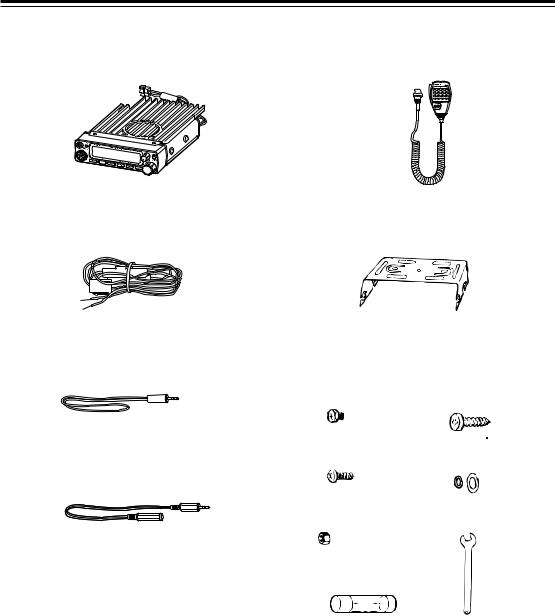
2. Standard Accessories
Carefully unpack to make sure the following items are found in the package in addition to this manual:
• Transceiver |
• Microphone EMS-53 or EMS-57 (with |
|
DTMF keypad) |
• DC power cable with fuse holder (UA0038) |
• Mobile mounting bracket. (FM0078Z) |
||||||
|
|
|
|
|
|
|
|
|
|
|
|
|
|
|
|
• Alarm cable A (with wire) (UX1259) |
• Hardware kit for bracket |
|
|
Black screws (M4*8mm) |
Tapping screws |
|
4pcs. (AE0012) |
(M5*20mm) 4pcs. (AJ0003) |
• Alarm cable B (extension use) (UX1260)
•Theft Alarm stickers 2pcs. (PR0454)
•Instruction manual (PS0349)
Screws (M5*20mm) |
Washer (AZ0010) |
4pcs. (AA0013) |
S-washer (AZ0009) |
Hexagonal nut (M5) 4pcs. |
Small (spanner) wrench. |
(AN0002) |
(FM0079) |
Spare fuses (a pair) |
|
2pcs. (EF0005) |
|
The standard accessories may vary slightly depending on the version you have purchased. Please contact your local authorized Alinco dealer should you have any questions. ALINCO and authorized dealers are not responsible for any typographical errors there may be in this manual. Standard accessories may change without notice.
Warranty Policy:
Please refer to any enclosed warranty information or contact your authorized Alinco dealer / distributor for the warranty policy.
5

3. Initial Installation
Connect the microphone to the front panel of the transceiver.
Connect antenna port to a 50 ohm antenna that covers the two-meter band, using good quality 50 ohm coaxial cable.
Microphone Antenna
External speaker |
rear panel |
|
|
(if used) |
|
For a base station set up
The Transceiver requires a 12-13.8VDC negative grounded power source.
Use a regulated power supply capable of providing continuous current of 12A or more.
Power supplies that do not meet those specifications may cause malfunction and/or damage to the radio and will void the warranty. Alinco offers excellent communication-grade power supplies as optional accessories. Please contact your local authorized Alinco dealer.
DC |
2 |
|
power supply |
||
|
Red lead
Black lead
DC power cable
1
6
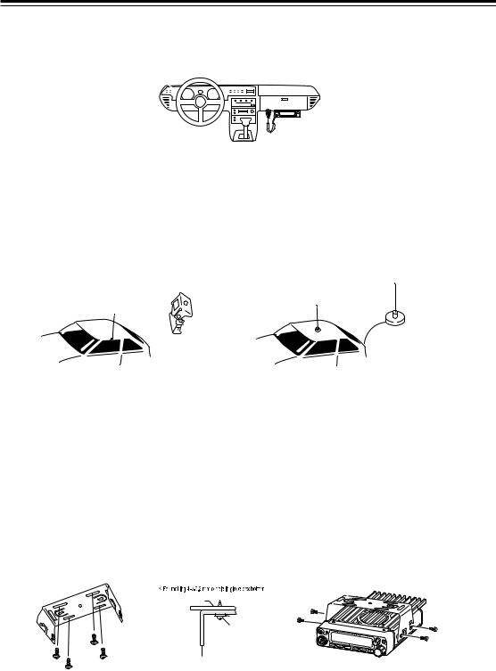
3. Initial Installation
For a mobile station set up
Location
The transceiver may be installed in any position in your car, where the controls and microphone are easily accessible and it does not interfere with the safe operation of the vehicle or the performance of the set. If your vehicle is equipped with air bags, be certain your radio will not interfere with their deployment. If you are uncertain about where to mount the unit, contact your vehicle's manufacturer.
Installing a Mobile Antenna
Magnet base
Screw-fixed base
Use a 50 ohm coaxial cable to connect the antenna. Mobile antennas require an appropriate mounting base for proper installation and operation. For more information, see the documentation for your antenna.
CAUTION: |
After installing your antenna, ensure that you have the best possible SWR reading. |
|
High RF environments can cause severe damage to your unit. Ensure that you are not |
|
in a high RF environment when operating the transceiver. |
|
|
Installing the Transceiver
See the figure on the below.
Car body
Washer (M5)
Tapping screw (M5 x 20 mm)
Mounting bracket
7
3. Initial Installation
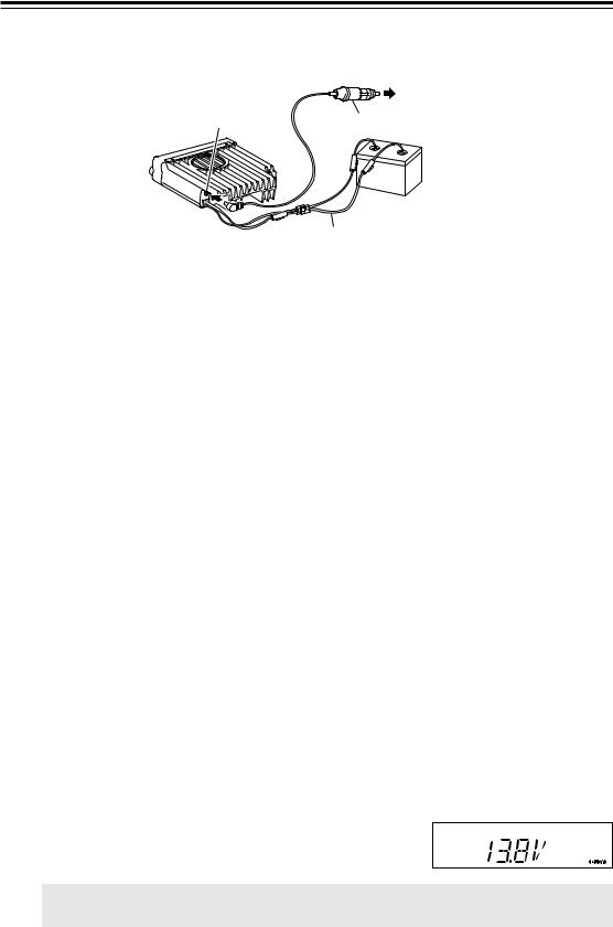
External power supply control & power lamp functions
|
ACC terminal |
Ext. Power jack |
Cigar-Plug connection |
|
Battery |
DC cable
Be sure the vehicle has a negative-ground, 12VDC electric system before installation. Connect the provided DC cable directly to the battery as shown below to minimize any possible ignition noise. Be sure the vehicle has a large capacity battery as the use of the transceiver may overload the electric system of the vehicle.
If the ignition-key on/off feature is desired (optional feature), use the optional EDC-37 (For direct connection to the circuit on the vehicle) or EDC-36 (for a Cigar-Plug connection) cable. Connect one of the cables between the ACC terminal or a Cigar-Plug that operates with the vehicle ignition or ACC switch on the vehicle and EXT POWER jack on the rear side of the unit. (Note: In many cars, the cigar-lighter plug is always powered. If this is the case, you cannot use it for the ignition key on/off function.) If this option is selected, the unit can be turned on/off either manually or automatically in accordance with the ignition key position:
1. When the ignition key is turned to ACC or ON (Start) position with the radio turned off, the power switch illuminates. The illumination will be turned off when the ignition key is turned to the off position. To turn on the unit, press the power switch manually while it is illuminated (while ignition key is at ACC or ON position).
2. When the ignition key is turned to ACC or ON position with the radio's power switch on, the unit turns on automatically and the power switch will be lit. Turn the ignition key to OFF position or manually turn the power switch off to shut down the radio.
The power consumption when using the additional cable is 5mA.
For operation without this option, use the power switch to turn the unit on/off.
Power supply voltage display function
After connecting the transceiver to the power supply, the supply voltage can be confirmed by pressing the SQL key together with the FUNC key. The supply voltage to the transceiver is then seen on the display.
The transceiver will return to its normal operation when the power is switched OFF.
The display immediately changes as the voltage supply changes.
It also displays voltage during transmission.
IMPORTANT: The range of the displayed voltage is only from 7V - 16VDC. Because the displayed value is estimated, please use a voltmeter when a more precise reading is desired.
8
4. Part Names and Functions
Front Panel
10 |
11 |
|
|
|
|
|
2 |
|
|
|
|
|
|
|
1 |
12 |
4 |
5 |
6 |
7 |
8 |
9 |
3 |
•Primary Functions
No. |
Key |
Function |
1 |
PWR |
Power turns ON / OFF whenever switch is pressed. |
|
|
|
2 |
Volume knob |
Adjusts the volume level. |
|
|
|
3 |
Dial |
Changes the frequency, memory channel and scan direction. |
4 |
FUNC/SET |
Sets the function mode to access additional settings. |
|
|
|
5 |
V/M/MW |
Switches between VFO mode and memory mode. |
|
|
|
6 |
MHZ/SHIFT |
Changes the frequency in 1 MHz steps. |
7 |
TS/DCS/LOCK |
Sets the tone squelch and DCS setting. |
|
|
|
8 |
CALL/H/L |
Switches to CALL mode. |
|
|
|
9 |
SQL/D |
Sets the squelch level |
10 |
DATA Terminal |
Used in clone and theft alarm functions. |
|
|
|
11 |
TX Light indicator |
Lights during transmission. |
|
|
|
12 |
Mic. Connector |
Connection port for supplied microphone. |
•Functions which can be activated while F appears, after pressing the FUCN Key.
No. |
Key |
Function |
4 |
FUNC/SET |
Confirms selection of other functions and exits the function mode. |
|
|
|
5 |
V/M/MW |
Write in to memory channel. |
|
|
|
6 |
MHZ/SHIFT |
Sets the shift direction and the offset frequency. |
|
|
|
7 |
TSDCS/LOCK |
Sets the key lock function. |
|
|
|
8 |
CALL/H/L |
Switches between HI, MID, and LOW power transmission. |
9 |
SQL/D |
Accesses the packet communication mode. / AM reception mode (DR-235T only) |
9
4. Part Names and Functions
•Functions that can be activated while pressing the FUNC Key
No. |
Key |
Function |
1 |
PWR |
Reset to factory default settings. |
|
|
|
5 |
V/M/MW |
Erase the memory. |
6 |
MHZ/SHIFT |
Switches to wide / narrow mode reception. |
|
|
|
7 |
TSDCS/LOCK |
Sets the auto dialer. |
|
|
|
8 |
CALL/H/L |
Accesses the clone function mode. |
|
|
|
9 |
SQL/D |
Accesses the power supply voltage indication mode. |
• Functions that require continuous pressing to be activated.
No. |
Key |
Function |
4 |
FUNC/SET |
When pressed for 2 seconds, accesses the set mode. |
|
|
|
9 |
SQL/D |
When pressed, within 1 second the monitor function is on. |
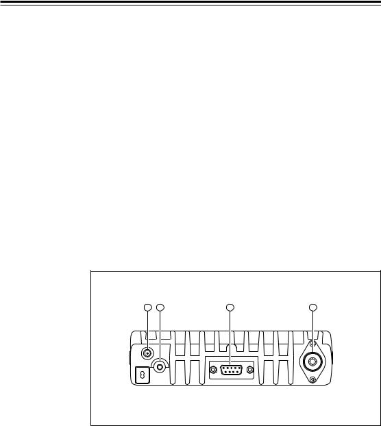
Rear Panel
1 |
2 |
3 |
4 |
No. |
Key |
Function |
1 |
Ext. Power jack |
Terminal for connecting optional EDC-37 for |
|
|
use with ignition key on/off function. |
2 |
External Speaker Terminal |
Terminal for optional external speaker |
|
|
|
3 |
DSUB-9 Connector |
Terminal where external TNC may be con- |
|
|
nected for packet use. With optional EJ-41U, |
|
|
connects internal TNC to the computer. |
4 |
Antenna Connector |
Connection for 50 ohm coaxial cable and |
|
|
antenna. |
10
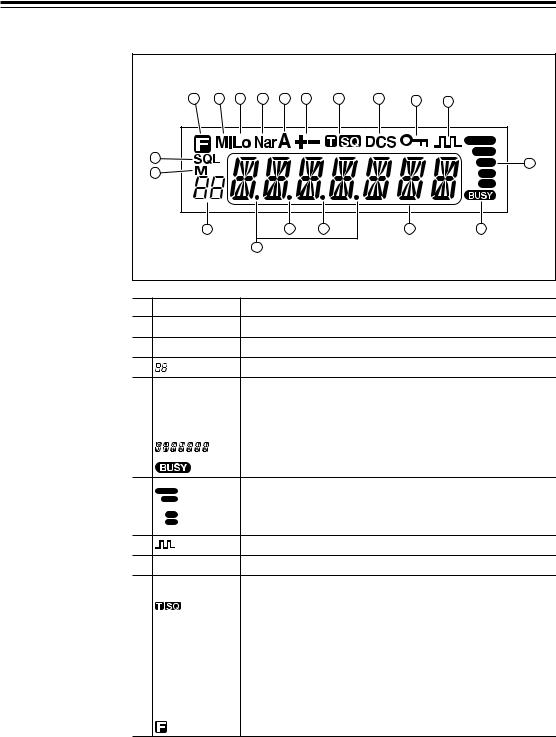
4. Part Name of Functions
Display
|
19 |
18 |
17 |
16 |
15 |
14 |
13 |
12 |
11 |
10 |
|
1 |
|
|
|
|
|
|
|
|
9 |
|
|
|
|
|
|
|
|
|
|
|
|
2 |
|
|
|
|
|
|
|
|
|
|
|
3 |
|
|
5 |
|
6 |
|
7 |
8 |
|
|
|
|
4 |
|
|
|
|
|
|
No. Key |
|
|
Function |
|
|
|
|
|
||
1 |
SQL |
|
|
Appears when setting the squelch level. |
||||||
2 |
M |
|
|
Appears when in memory mode. |
|
|||||
3 |
|
|
|
Indicates the memory channel number in memory mode. |
||||||
4 |
.Decimal point |
Appears when setting the theft alarm function. |
5 |
.Decimal point |
Appears when setting the skip level. |
|
|
|
6 |
.Decimal point |
Indicates the decimal point of frequency and the scanning function. |
|
|
|
7 |
|
Indicates the frequency or memory name. |
|
|
|
8 |
|
Appears when a signal is being received. |
9 S-meter Indicates the relative signal strength level of transmission / reception.
10 |
Appears when in packet mode. |
11  key lock Appears when setting the key lock.
12 |
DCS |
Appears when setting the DCS. |
13 |
|
Appears when setting the tone squelch. |
|
|
|
14 |
+- |
Appears when setting the shift. |
|
|
|
15 |
A |
Appears during AM reception. |
|
|
|
16 |
Nar |
Appears when in narrow band reception mode. |
|
|
|
17 |
Lo |
Appears when transmission power is set to LOW. |
|
|
|
18 |
Mi |
Appears when transmission power is set to MID. |
|
|
|
19 |
|
Appears when FUNC Key is pressed. |
11
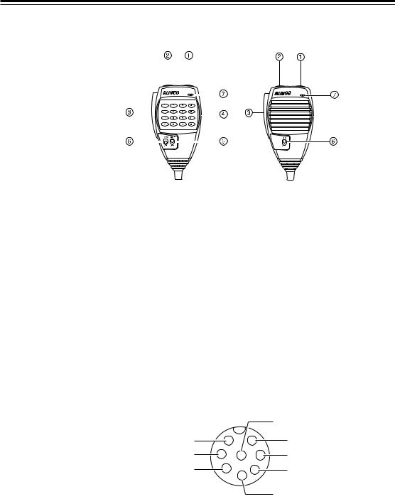
4. Part Names and Functions
Microphone
|
|
|
|
|
|
|
|
|
|
|
|
|
|
|
|
|
|
|
|
|
|
|
|
|
|
|
|
|
|
|
|
|
|
|
|
|
|
|
|
|
|
|
|
|
|
|
|
|
|
|
|
|
|
|
|
|
|
|
|
|
|
|
|
|
|
|
|
|
|
|
|
|
|
|
|
|
|
|
|
|
|
|
|
|
|
|
|
|
|
|
|
|
|
|
|
|
|
|
|
|
|
|
|
|
|
|
|
|
|
|
|
|
|
|
Standard |
Option |
|||||||||
|
|
|
|
|
|
|
|
|
|
|
|
|
|
|
|
|
|
||||||||||
No. |
Key |
Function |
|
||||||||||
1 |
UP |
Increase the frequency, memory channel number, or setting value. |
|||||||||||
2 |
DOWN |
Decrease the frequency, memory channel number, or setting value. |
|||||||||||
|
|
|
|||||||||||
3 |
PTT |
Press the PTT(Push-To-Talk)key to transmit. |
|||||||||||
|
|
|
|
||||||||||
4 |
DTMF |
DTMF tone keys |
|
||||||||||
|
DTMF / REMOTE |
Set to DTMF when you don’t want to operate remote con- |
|||||||||||
5 |
trol functions. So that DTMF keys do not function except |
||||||||||||
|
Switch |
||||||||||||
|
|
during transmit to send DTMF codes manually. |
|||||||||||
|
|
|
|
|
|
||||||||
|
|
|
|||||||||||
6 |
Lock Switch |
Locks out the UP and DOWN keys. |
|||||||||||
|
|
|
|||||||||||
7 |
MIC |
Speak here during transmission. |
|||||||||||
Mic. Connector Diagram (While looking in the front view of the con-
nector)
|
|
|
GND |
MIC |
1 |
7 |
MIC GND |
PTT |
2 |
8 6 |
Remote control |
DOWN |
3 |
5 |
DC 5V |
|
|
4 |
|
UP
12

5. Basic Operations
Turning the unit on and off
Press the power switch or turn the ignition key to ACC or ON position according to the option selected during installation. Press the power switch again or turn the ignition key to OFF position to turn off.
Audio Volume level setting
Rotate the VOL knob clockwise to increase the audio level, counterclockwise to decrease. Set it at the desired level.
Squelch level setting
A squelch eliminates white-noise (the background noise when a signal is not received).
Higher level settings will keep the squelch “closed” more tightly for quieter monitoring, but weak signals will not be heard. Lower settings allow weaker signals to “open” the squelch but noise may also cause it to open.
1. Press SQL key. SQL icon appears on the display and the squelch level will be shown at the position where the memory number is displayed. 21 levels, between 0 and 20, are available. “0” is the lowest setting.
2. By rotating the main dial or by using the UP/ DOWN keys on the microphone, adjust the squelch to the desired level. To return to normal use, press PTT or any key on the front panel; or if there are no operations within 5 seconds, the unit will store the setting and will return to its original status.
The new squelch level will be stored in the CPU until another adjustment is done.
PWR key
Minimum Maximum
volume volume
VOL knob
Squelch level
13
 Loading...