


A1.140220
ALINCO, INC.
Yodoyabashi Dai-bldg 13F
4-4-9 Koraibashi, Chuo-ku, Osaka 541-0043 Japan
Phone: +81-6-7636-2362 Fax: +81-6-6208-3802 http://www.alinco.com E-mail:export@alinco.co.jp
VHF/UHF FM Transceiver DR638
All EU and EFTA member states. Operator license is required.
FCC ID:PH3-DR638 IC:3070C-DR638
Copyright Alinco, lnc. PS0665A/FNEG-NI
Printed in China

VHF/UHF FM Transceiver
DR-638
Instruction Manual
Thank you for purchasing your new Alinco transceiver. Please read this manual carefully before using the product to ensure full performance, and keep this manual for future reference as it contains information on after-sales services. In case addendum or errata sheets are included with this product, please read those materials and keep them together with this instruction manual for future reference.
NOTE: DR-638 may be delivered to you after dealer-programming. In such cases, please ask your dealer about the available features in your unit and how to operate this unit.
Introduction
Thank you very much for purchasing this excellent Alinco transceiver. Our products are ranked among the finest in the world. This radio has been manufactured with state of the art technology and it has been tested carefully at our factory. It is designed to operate to your satisfaction for many years under normal use.
Please read this manual completely from the first page to the last, to learn all the functions the product offers. It is important to note that some of the operations may be explained in relation to information in previous chapters. By reading just one part of the manual, you may risk not understanding the complete explanation of the function.
Before transmitting
There are many radio stations operating in proximity to the frequency ranges this product covers. Be careful not to cause interference when transmitting around such radio stations.
■ Lightning
Please note that no car provides adequate protection of its passengers or drivers against lightning. Therefore, Alinco will not take responsibility for any danger associated with using its radios or inside the car during lightning.
■ For North American users
Due to strict rules, this product is blocked for operations before sales and only dealers can program the radio before delivery to consumers. Manufacturer is not aware of details of such dealer-programming therefore please kindly contact your dealer first in case technical-service may be necessary.
Conformity Symbols
Tested to comply MIL-STD-810G
-Shock: Method 514.6/I,IV -Vibration: Method 516.6/I
Conformity Information
In case the unit you have purchased is marked with a CE symbol,a copy of relative conformity certificate or docu-ment can be reviewed at http:// www.alinco.com/usa.html.Please see the back-cover for more details.
Copyright 2012 All rights reserved. NO part of this document may be reproduced, copied, translated or transcribed in any form or by any means without the prior writhout the prior written permission of Alinco.
Inc,Osaka, Japan, English Edition Printed in China.
Comformity information / Amateur radio version Manufacturer:
ALINCO, Inc. Electronics Division
Yodoyabashi Dai-bldg. 13F
4-4-9 Koraibashi, Chuo-ku,
Osaka 541-0043 Japan

FCC NOTICE / Compliance Information Statement
This equipment has been tested and found to comply with the limits for a
Class B digital device, pursuant to part 15 of the FCC Rules.
These limits are designed to provide reasonable protection against harmful interference in a residential installation.
This equipment generates, uses, and can radiate radio frequency energy and, if not installed and used in accordance with the instruction manual, may cause harmful interference to radio communications. However, there is no guarantee that interference will not occur in a particular installation. If this equipment does cause harmful interference to radio or television reception, which can be determined by turning the equipment off and on, the user is encouraged to try to correct the interference by one or more of the following measures:
•Reorient or relocate the receiving antenna.
•Increase the separation between the equipment and receiver.
•Connect the equipment into an outlet on a circuit different from that to which the receiver is connected.
•Consult the dealer or an experienced radio/TV technician for help.
Tested to Comply
With FCC Standards
FOR HOME OR OFFICE USE
Information in this document is subject to change without notice or obligation. All brand names and trademarks are the property of their respective owners. Alinco cannot be liable for pictorial or typographical inaccuracies. Some parts, options and/or accessories are unavailable in certain areas. Changes or modifications not expressly approved by the party responsible for compliance could void the user's authority to operate the equipment.
This device complies with Part 15 of the FCC Rules. Operation is subject to the following two conditions: (1) This device may not cause harmful interference, and (2)this device must accept any interference received, including interference that may cause undesired operation.
customers in Canada : MODEL: 3070C-DR638
Le présent appareil est conforme aux CNR d'Industrie Canada applicables aux appareils radio exempts de licence. L'exploitation est autorisée aux deux conditions suivantes :
(1)l'appareil ne doit pas produire de brouillage, et.
(2)l'utilisateur de l'appareil doit accepter tout brouillage radioélectrique subi, même si le brouillage est susceptible d'en compromettre le fonctionnement.
CE Conformity Information
This device is in compliance with the essential requirements of R&TTE
Directive 1999/5/EC.
A copy of the certificate by the notified body can be reviewed at http:// www.alinco.com/usa.html.
This device is authorized for use in all EU and EFTA member states.
An operator's license is required for this device.

Trash bin icon / Rohs Icon
IMPORTANT: This manual is common to amateur and commercial users.
Not all features are available to commercial users. Commercial-use units are programmed by the dealer before sales therefore features may be prohibited for manual access by the users.
Commercial-users should contact the dealer for any technical inquiry because the distributor and manufacturer are not aware of the details of dealer-programming.
Features like sclambling is not allowed for amateur radio communications.

SAFETY TRAINING INFORMATION Land-mobile version only
WARNING:
This radio generates RF electromagnetic energy during transmission. This radio is designed for and classified as “Occupational Use Only”, meaning it must be used only during the course of employment by individuals aware of the hazards, and the ways to minimize such hazards.This radio is NOT intended for use by the “GeneralPopulation” in an uncontrolled environment.
• For compliance with FCC and Industry Canada RF Exposure Requirements, the transmitter antenna installation shall comply with the following two conditions:
1.The transmitter antenna gain shall not exceed 0 dBi.
2.The antenna is required to be located outside of a vehicle and kept at a distance of 63 centimeters or more between the transmitting antenna of this device and any persons during operation.For small vehicle as worst case, the antenna shall be located on the roof top at any place on the centre line along the vehicle in order to achieve
63 centimeters separation distance. In order to ensure this distance is met, the installation of the antenna must be mounted at least 63 centimeters away from the nearest edge of the vehicle in order to protect against exposure to bystanders.
CAUTION:
To ensure that your exposure to RF electromagnetic energy is within the FCC allowable limits for occupational use, always adhere to the following guidelines:
•DO NOT operate the radio without a proper antenna attached, as this may damage the radio and may also cause you to exceed FCC RF
exposure limits. A proper antenna is the antenna supplied with this radio by the manufacturer or an antenna specifically authorized by the manufacturer for use with this radio.
• DO NOT transmit for more than 50% during the time of employment
(50% duty cycle or less). Transmitting excessive amount of time can cause RF exposure compliance requirements to be exceeded. Please carefully read this instruction manual to learn how to transmit and stop transmitting before starting to use it.
Electromagnetic Interference/Compatibility
During transmissions, your radio generates RF energy that can possibly cause interference with other devices or systems. To avoid such interference, turn off the radio in areas where signs are posted to do so. DO NOT operate the transmitter in areas that are sensitive to electromagnetic radiation such as hospitals, aircraft, and blasting sites.
Occupational/Controlled Use
This product is used in situations that users are exposed to RF as consequence of their employment provided those users are fully aware of the potential RF hazards and can exercise control over their exposure.
•This transceiver is NOT ATEX approved and NOT intended for the use in hazardous explosive atmospheres.
PC PROGRAMMING
NOTE: The utility software may be available to distributors/dealers only. USB programming cable is required. The manufacturer will not release the software to unauthorized party so please contact your dealer for details.

FCC INFORMATION / LAND-MOBILE VERSION ONLY
FOR CLASS B UNINTENTIONAL RADIATORS:
This equipment has been tested and found to comply with the limits for a Class B digital device, pursuant to part 15 of the FCC Rules.
These limits are designed to provide reasonable protection against harmful interference in a residential installation.
This equipment generates, uses and can radiate radio frequency energy and, if not installed and used in accordance with the instructions, may cause harmful interference to radio communications. However, there is no guarantee that interference will not occur in a particular installation.
If this equipment does cause harmful interference to radio or television reception, which can be determined by turning the equipment off and on, the user is encouraged to try to correct the interference by one or more of the following measures:
●● Reorient or relocate the receiving antenna.
●● Increase the separation between the equipment and receiver.
●● Connect the equipment into an outlet on a circuit different from that to which the receiver is connected.
●● Consult the dealer or an experienced radio/TV technician for help.
For CustOMERS in Canada :
Le présent appareil est conforme aux CNR d'Industrie Canada applicables aux appareils radio exempts de licence.
L'exploitATION est autORISée aux deux conditions suivANTES :
(1)l'appareil ne doit pas produire de brouillage, et
(2)l'utilisateur de l'appareil doit accepter tout brouillage radioélectrique subi, même si le brouillage est susceptible d'en compromettre le fonctionnement.
To prevent any hazard during operation of Alinco’s radio product, in this manual and on the product you may fi nd symbols shown below. Please read and understand the meanings of these symbols before starting to use the product.
This symbol is intended to alert the user to an Danger immediate danger that may cause loss of life and
property if the user disregards the warning.
This symbol is intended to alert the user to a possible Alert hazard that may cause loss of life and property if the
user disregards the warning.
This symbol is intended to alert the user a possible
Caution hazard that may cause loss of property or injure the user if the warning is disregarded.
Alert symbol. An explanation is given.
Warning symbol. An explanation is given.
Instruction symbol. An explanation is given.
 ALERT
ALERT
 Environment and condition of use:
Do not drive while handling the radio for your safety. It is recommended that you check local traffi c regulations regarding the use of radio equipment while driving.
Some countries prohibit the operation of transceiver while driving.
WARNING
Do not use this product in close proximity to other electronics devices, especially medical ones. It may cause interference to those devices.
Keep the radio out of the reach of children.
In case a liquid leaks from the product, do not touch it. It may damage your skin.
Rinse with plenty of cold water if the liquid contacted your skin.
Never operate this product in facilities where radio products are prohibited for use such as aboard aircraft, in airports, in ports, within or near the operating area of business wireless stations or their relay stations.
Use of this product may be prohibited or illegal outside of your country. Be informed in advance when you travel.
The manufacturer declines any responsibilities against loss of life and/or property due to a failure of this product when used to perform important tasks like life-guarding, surveillance, and rescue.
Do not use multiple radios in very close proximity. It may cause interference and/or damage to the product(s).
The manufacturer declines any responsibilities against loss of life and property due to a failure of this product when used with or as a part of a device made by third parties.
Use of third party accessory may result in damage to this product. It will void our warranty for repair.
 WARNING
 Handling this product:
Be sure to reduce the audio output level to minimum before using an earphone or a headset. Excessive audio may damage hearing.
Do not open the unit without permission or instruction from the manufacturer.
Unauthorized modification or repair may result in electric shock, fire and/or malfunction.
Do not operate this product in a wet place such as shower
 room. It may result in electric shock, fire and/or malfunction.
Do not place conductive materials, such as water or metal in close proximity to the product. A short-circuit to the product may result in electric shock, fire and/or malfunction.
Do not touch the heatsink (on/around the unit mostly found on mobile-base units) as it may become very hot during/after the operation that may risk burn your skin.
 About power-supply:
Use only appropriate, reliable and certified power supply of correct voltage and capacity.
Do not connect cables in reverse polarity. It may result in electric shock, fire and/or malfunction.
Do not plug multiple devices including the power-supply into a single wall outlet. It may result in overheating and/or fire.
Do not handle a power-supply with a wet hand. It may result in electric shock.
Do not plug the power-supply into the wall outlet if the contacts are dirty and/or dusty.
Shortcircuiting and/or overheating may result in fire, electric shock and/or damage to the product.
Do not modify or remove fuse-assembly from the DC-cable. It may result in f ire, electric shock and/or damage to the product.
 In case of emergency:
In case of the following situation(s), please turn off the product, switch off the source of power, then remove or unplug the power-cord. Please contact your local dealer of this product for service and assistance.
Do not use the product until the trouble is resolved. Do not try to troubleshoot the problem by yourself.
•When a strange sound, smoke and or strange odor comes out of the product.
•When the product is dropped or the case is broken or cracked.
•When a liquid penetrated inside.
•When a power-cord ( including DC-cables, AC-cables and adapters) is damaged.
For your safety, turn off then remove all related AC-lines to the product and its accessories including the antenna if a thunderstorm is likely.
Turn off the unit, remove the mobile antenna from its base and keep it in the vehicle if a thunderstorm is likely.
Please read cautions regarding the lightning-protection on page 9 also.
 Maintenance
Securely plug the power-supply to the wall outlet. Insecure installation may result in short-circuit, electronic shock and/or fire.
Do not open the unit and its accessories. Please consult with your local dealer of this product for service and assistance.
 CAUTION
 Environment and condition of use:
Do not use the product in proximity to a TV or a radio. It may cause interference or receive interference.
Do not install in a humid, dusty or insufficiently ventilated place. It may result in electric shock, fire and/or malfunction.
Do not install in an unstable or vibrating position. It may result in electric shock, fire and/or malfunction when/if the product falls to the ground.
Do not install the product in proximity to a source of heat and humidity such as a heater or a stove. Avoid placing the unit in direct sunlight.
Do not modify, dismantle, incinerate, or immerse the batteries that may be used in accessories you use with this product.
Please check your local regulations for details on recycling option or disposal of the batteries in your area.
 About transceiver
Do not connect devices other than specifi ed ones to the jacks and ports on the product.
It may result in damage to the devices.
Turn off and remove the power-source (AC cable, DC cable, battery, cigar-cable, charger adapter etc) from the product when the product is not in use for extended period of time or in case of maintenance.
Use a clean, dry cloth to wipe off dirt and condensation from the surface of the product.
Never use thinner or benzene for cleaning.
WARNING 
About power-supply
Always turn off the power supply when connecting or disconnecting the cables.
When using an external antenna, make sure that the antenna ground is not common with the ground of the power supply.
European users: When a transceiver is powered from an external DC power source (adapter, power supply, cigar-plug etc), make sure that this power supply has approval to the level of IEC/EN 60950-1.
CONTENTS
New and Innovative Features............................................... |
1 |
Supplied Accessories/Optional Accessories..................... |
2 |
Supplied Accessories....................................................................... |
2 |
Initial Installation................................................................... |
3 |
Mobile installation............................................................................. |
3 |
DC Power Cable Connection............................................................ |
4 |
Power supply voltage Display........................................................... |
6 |
Antenna Connection......................................................................... |
6 |
Accessories Connections................................................................. |
6 |
Getting Acquainted............................................................... |
8 |
Front panel....................................................................................... |
8 |
Rear panel........................................................................................ |
9 |
Display.............................................................................................. |
9 |
Microphone ...................................................................................... |
10 |
Basic Operations .................................................................. |
11 |
Switching the Power On/Off............................................................. |
11 |
Adjusting the Volume........................................................................ |
11 |
Squelch level setting......................................................................... |
11 |
Switch between VFO and memory mode......................................... |
11 |
Setting frequency.............................................................................. |
11 |
Setting channel................................................................................. |
11 |
Switch Between Main Band and Sub band...................................... |
12 |
Selecting the operating band............................................................ |
12 |
Receiving.......................................................................................... |
12 |
Squelch Off/Squelch Off Momentary................................................ |
12 |
Transmitting...................................................................................... |
13 |
Transmit DTMF/2TONE/5TONE signaling........................................ |
13 |
High/Mid/Low Power Setting............................................................ |
13 |
Frequency Reverse.......................................................................... |
13 |
CTCSS/DCS setting......................................................................... |
13 |
Call channel recalling....................................................................... |
13 |
CTCSS/DCS Scan............................................................................ |
14 |
Dual Watch....................................................................................... |
14 |
Emergency Alarm............................................................................. |
14 |
Channel/Frequency Scan................................................................. |
14 |
Channel Scan Skip........................................................................... |
14 |
Memory Channel Programming........................................................ |
14 |
Search Scan Range Setting............................................................. |
14 |
Channel Copy................................................................................... |
15 |
Channel Delete................................................................................. |
15 |
Memory Banks operation.................................................................. |
15 |
PARAMETER SETTING MODE(SET MODE)........................ |
16 |
Menu 01: APO (Automatic power off)............................................... |
16 |
Menu 02: Automatic offset................................................................ |
16 |
Menu 03: VFO Channel Step Setting............................................... |
16 |
Menu 04: VFO Band lockout............................................................ |
16 |
Menu 05: Beep Sound...................................................................... |
17 |
Menu 06: CPU Clock Frequency Setting.......................................... |
17 |
Menu 07: 2Tone Encode Select........................................................ |
17 |
Menu 08: 5Tone Encode Select........................................................ |
17 |
Menu 09: Add Optional Signaling..................................................... |
18 |
Menu 10: Tone Encode Setup.......................................................... |
18 |
Menu 11: Tone Decode Setup ......................................................... |
18 |
Menu 12: Sub Band Display............................................................. |
19 |
Menu 13: DTMF Encode Pre-Loading Timing.................................. |
19 |
Menu 14: DTMF Encode Transmitting Time..................................... |
19 |
Menu 15: DTMF Encode Setup........................................................ |
19 |

CONTENTS
Menu 16: Squelch Mode Setup........................................................ |
20 |
Menu 17: Compander....................................................................... |
20 |
Menu 18: Scrambler (Available to Commercial models only ).......... |
20 |
Menu 19: Tone Burst Tones.............................................................. |
20 |
Menu 20: Hyper................................................................................ |
21 |
Menu 21: Keypad Lockout................................................................ |
21 |
Menu 22: PTT Lockout..................................................................... |
21 |
Menu 23: TOT Penalty...................................................................... |
21 |
Menu 24: Talk Around....................................................................... |
21 |
Menu 25: SUB Band Mute................................................................ |
22 |
Menu 26: Editing Memory Name...................................................... |
22 |
Menu 27: Time-Out Timer(TOT)....................................................... |
22 |
Menu 28-31: Microphone PA,PB, PC,PD key setup ........................ |
22 |
Menu 32: RF Squelch....................................................................... |
23 |
Menu 33: Offset Direction................................................................. |
23 |
Menu 34: Scan Resume Condition................................................... |
23 |
Menu 35: Priority Channel Scan....................................................... |
24 |
Menu 36: Offset Frequency.............................................................. |
24 |
Menu 37: Display Mode.................................................................... |
24 |
Menu 38: Busy Channel Lockout(BCLO)......................................... |
24 |
Menu 39: DTMF Self ID Enquiry....................................................... |
24 |
Menu 40: 5-TONE Self ID Enquiry................................................... |
25 |
Menu 41: VFO Frequency Linkage................................................... |
25 |
Menu 42: Wide/Narrow FM Mode..................................................... |
25 |
Menu 43: Crossband Repeat (HE model not available)................... |
25 |
Menu 44-46: LCD backlight.............................................................. |
26 |
Menu 47: Keypad backlight brightness............................................. |
26 |
Menu 48: Calling Record.................................................................. |
26 |
Menu 49: AM Function...................................................................... |
26 |
Menu 50: Automatic AM function...................................................... |
26 |
Menu 51: VHF External speaker port .............................................. |
27 |
Menu 52: Beep Volume control ....................................................... |
27 |
Menu 53: Talk Around ...................................................................... |
27 |
Menu 54: Microphone Speaker........................................................ |
27 |
MENU 55: Memory Banks Enquiry................................................... |
27 |
MENU 56: Memory Banks Linking.................................................... |
28 |
Menu 64: Password Function........................................................... |
28 |
Microphone Operation.......................................................... |
29 |
Send DTMF signaling....................................................................... |
29 |
Main/Sub band switching.................................................................. |
29 |
Function operation through PA-PD keys.......................................... |
29 |
Main/Sub band switching.................................................................. |
29 |
Main/Sub band switching.................................................................. |
29 |
Cable Clone........................................................................... |
31 |
Resume Factory Default................................................................... |
31 |
Programming Software Installing and Starting (in windows |
|
XP syst1e0m)......................................................................... |
32 |
Install USB Cable Driver Programme............................................... |
32 |
Maintenance.......................................................................... |
33 |
Trouble Shooting.............................................................................. |
33 |
Specifications........................................................................ |
34 |
Appendix................................................................................ |
35 |
51 groups CTCSS Tone Frequency(Hz)........................................... |
35 |
1024 groups DCS Code................................................................... |
35 |

1 New and Innovative Features
758 memory channels, full duplex operation with independent volume and squelch controls
50 Watts of power output on the VHF band and 40 Watts on the UHF band with cross band repeater function.
UU, UV,VU,VV operations with full-dupe and wideband receive capability including Air band in AM and FM broadcast.
A large LCD with selectable backlit color, Keys and microphone keypads are also backlit and ensures comfortable operation in the dark.
CTCSS, DCS, 2-tones, 5-tones and tone-bursts for repeater access and sellective calling operations.
1Various scan functions including CTCSS/DCS Scan function.
Variety of signaling such as emergency alarm, ANI/DTMF, remotekill/revive features.
Multi groups of fix scrambling and 2 groups of self define scrambling.(commercial models)
Compander function to decrease the background noise and enhance audio clarity.(commercial models)
Theft alarm provides extra safety.
Operating Frequency Ranges
<Band 1> *For DR638
Tx: 136-174MHz 400-480MHz Rx: 108-180MHz 220-260MHz
350-399.995MHz
400-523MHz

Supplied Accessories 2
 SUPPLIED ACCESSORIES
Carefully unpack to make sure the following items are found in the package in addition to this manual:
Transceiver |
Microphone EMS-74 |
Mobile Mounting |
DC Power Cable with |
Hardware Kit for Bracket |
|
|
DR-638 |
(with DTMF keyboard) |
Bracket |
Fuse Holder |
Black screws |
Tapping screws |
S-Washer |
|
|
|
|
(M4X8mm) |
(M5X8mm) |
|
|
|
|
|
4PCS |
4PCS |
|
 Spare Fuses
2
The standard accessories may vary slightly depending on the version you have purchased. Please contact your local authorized Alinco dealer should you have any questions. Alinco and authorized dealers are not responsible for any typographical errors there may be in this manual. Standard accessories may change without notice.
Warranty Policy: Please refer to any enclosed warranty information or contact your authorized Alinco dealer / distributor for the warranty policy.
■In order to operate this product, a properly tuned antenna, its feedline with connectors and fixing hardware are necessary. Please consult with your dealer for details.
3 |
Initial Installation |
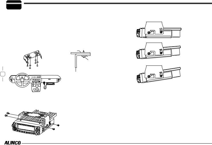
 MOBILE INSTALLATION
The transceiver may be installed in any position in your car, where the controls and microphone are easily accessible and it does not interfere with the safe operation of the vehicle. If your vehicle is equipped with air bags, be certain your radio will not interfere with their deployment. If you are uncertain about where to mount the unit, contact your vehicle's dealer.
1.Install the mounting bracket in the vehicle using the supplied selftapping screws (4pcs) and flat washers (4pcs).
Car body
Washer (M5) Tapping screw (M5x20mm)
3 |
Mounting bracket |
2.Position the transceiver, then insert and tighten the supplied hexagon SEMS screws.
Double check that all screws are tightened to prevent vehicle vibration from loosening the bracket or transceiver.
Caution:
Use only the provided screws otherwise you risk damaging the circuit board, components or falloff of the unit.
Determine the appropriate angle of the transceiver, using the 3 screw hole positions on the side of the mounting bracket.
 Loading...