


UHF FM TRANSCEIVER
DJ-S45 CQ/T/E
Instruction Manual
Thank you for purchasing this ALINCO FM transceiver. This instruction manual contains important safety and operating instructions.
Please read it carefully before using the transceiver and be sure to keep it for future reference.
ALINCO, INC.

Contents
Contents
NOTICE / Compliance Information Statement ..................... |
3 |
||
Before Operating the Transceiver ......................................... |
5 |
||
1.Functions and Features....................................................... |
6 |
||
1-1 |
Standard Accessories .............................................................. |
6 |
|
2.Accessories .......................................................................... |
7 |
||
2-1 Attaching and Detaching Accessories..................................... |
7 |
||
2-1-1 |
Antenna( DJ-S45 T/E only)............................................. |
7 |
|
2-1-2 |
Hand Strap ...................................................................... |
7 |
|
2-1-3 |
Belt Clip.......................................................................... |
7 |
|
2-2 |
Setting Batteries ...................................................................... |
8 |
|
2-3 Lithium Ion Battery Pack ........................................................ |
8 |
||
2-4 |
Battery Level Indicator ........................................................... |
9 |
|
3.Control Functions............................................................... |
10 |
||
3-1 Names and Operations of the Transceiver Controls ............. |
10 |
||
3-2 |
Key Operations...................................................................... |
12 |
|
3-3 |
Display .................................................................................. |
14 |
|
4.Basic Operations................................................................ |
15 |
||
4-1 Turning the Power ON .......................................................... |
15 |
||
4-2 Adjusting the Audio Volume ................................................ |
15 |
||
4-3 |
Operating Modes................................................................... |
16 |
|
4-4 |
LPD (VFO) Mode ................................................................. |
16 |
|
4-4-1 |
Frequency Setting ......................................................... |
17 |
|
4-5 |
PMR Mode( DJ-S45 CQ only) .............................................. |
17 |
|
4-5-1 |
Frequency Number Setting........................................... |
17 |
|
4-6 |
Memory Mode....................................................................... |
18 |
|
4-6-1 |
Memory Channel Programming ................................... |
18 |
|
4-6-2 Selecting a Memory Channel ....................................... |
19 |
||
4-6-3 Clearing a Memory Channel Data ................................ |
19 |
||
4-6-4 Programmable Items to Memory Channel.................... |
20 |
||
1

|
|
|
|
Contents |
|
|
|
|
|
4-7 |
Receiving .............................................................................. |
|
20 |
|
4-7-1 |
Adjusting Squelch Level .............................................. |
20 |
||
4-7-2 |
Monitor Function.......................................................... |
|
21 |
|
4-8 |
Transmitting .......................................................................... |
|
21 |
|
4-8-1 Switching of Transmission Output Level |
|
|||
|
|
( DJ-S45 T/E only) ........................................................ |
|
22 |
5.Parameter Setting Mode ................................................... |
|
23 |
||
5-1 |
Selectable Parameters............................................................ |
|
23 |
|
5-2 Selecting the Setting Mode ................................................... |
|
28 |
||
6.Advanced Operations ........................................................ |
|
30 |
||
6-1 |
Scanning................................................................................ |
|
30 |
|
6-1-1 |
LPD (VFO) Scan .......................................................... |
|
31 |
|
6-1-2 |
PMR Scan( DJ-S45 CQ |
only) ....................................... |
31 |
|
6-1-3 |
Memory Scan................................................................ |
|
32 |
|
6-1-4 |
Skip Channel................................................................. |
|
32 |
|
6-1-5 |
Tone Scan ..................................................................... |
|
33 |
|
6-2 |
Repeater( DJ-S45 T/E only)................................................... |
|
33 |
|
6-3 |
Key Lock............................................................................... |
|
34 |
|
6-4 Tone Call (Tone Burst) ......................................................... |
|
35 |
||
6-5 |
Channel Display Mode.......................................................... |
|
35 |
|
7.Selective Communicating ................................................. |
|
36 |
||
7-1 LPD (VFO) Tone Squelch .................................................... |
|
36 |
||
7-2 |
PMR Tone Squelch( DJ-S45 CQ only) ................................. |
38 |
||
8.Cloning / Packet Operation............................................... |
|
39 |
||
8-1 |
Cloning.................................................................................. |
|
39 |
|
8-2 |
Packet Operation( DJ-S45 T/E |
only) ..................................... |
42 |
|
9.Maintenance and Reference ............................................. |
|
43 |
||
9-1 |
Resetting................................................................................ |
|
43 |
|
9-2 |
Options .................................................................................. |
|
44 |
|
10.Specifications ................................................................... |
|
45 |
||
2

NOTICE / Compliance Information Statement
NOTICE / Compliance Information Statement
DJ-S45 T
This equipment has been tested and found to comply with the limits for a Class B digital device, pursuant to part 15 of the FCC Rules. These limits are designed to provide reasonable protection against harmful interference in a residential installation.
This equipment generates, uses, and can radiate radio frequency energy and, if not installed and used in accordance with the instruction manual, may cause harmful interference to radio communications. However, there is no guarantee that interference will not occur in a particular installation. If this equipment does cause harmful interference to radio or television reception, which can be determined by turning the equipment off and on, the user is encouraged to try to correct the interference by one or more of the following measures:
•Reorient or relocate the receiving antenna.
•Increase the separation between the equipment and receiver.
•Connect the equipment into an outlet on a circuit different from that to which the receiver is connected.
•Consult the dealer or an experienced radio/TV technician for help.
Tested to Comply
With FCC Standards
FOR HOME OR OFFICE USE
Information in this document is subject to change without notice or obligation. All brand names and trademarks are the property of their respective owners. Alinco cannot be liable for pictorial or typographical inaccuracies. Some parts, options and/or accessories are unavailable in certain areas. Changes or modifications not expressly approved by the party responsible for compliance could void the user's authority to operate the equipment.
3

NOTICE / Compliance Information Statement
UHF FM Transceiver DJ-S45 T
This device complies with Part 15 of the FCC Rules. Operation is subject to the following two conditions: (1) This device may not cause harmful interference, and (2) this device must accept any interference received, including interference that may cause undesired operation.
Manufacturer:
ALINCO, Inc Electronics Division
Shin-Dai Bldg 9F, 2-6, 1 Chome
Dojimahama, Kita-ku, Osaka 530-0004 JAPAN
DJ-S45 E DJ-S45 CQ
Conformity Information
In case the unit you have purchased is marked with a CE symbol, a copy of relative conformity certificate or document can be reviewed at http://www.alinco.com/usa.html.
Copyright © 2005 All rights reserved. No part of this document may be reproduced, copied, translated or transcribed in any form or by any means without the prior written permission of Alinco. Inc., Osaka, Japan, English Edition Printed in Japan.
4

Before Operating the Transceiver
 Caution
The use of transceiver in the following places is prohibited. •Aboard aircraft •In airports •In ports •Within or near the
operating area of business wireless stations or their relay stations.
Before using the transceiver in any of the above places, obtain any necessary permission from the proper authorities, and be mindful of the local laws that govern radio operation.
■ Points to Note for Using an External Power Supply
•When the power is supplied from a cigarette socket of a car, use the cigarette lighter cable (EDH-33).
•Turn the power off when connecting or disconnecting the DC cable.
•When using a commercial external antenna, install the antenna ground not to become common with the ground of the external power supply.
•This DC jack supports 3.0~6.0VDC, 2A or more external power source. Please use an appropriate, reliable power supply, and be mindful to the polarity (+ positive center).
•Use of non-genuine accessories will void ALINCO's factory warranty.
5

1.Functions and Features
1. Functions and Features |
1 |
■ 39 different Tone Squelch function (CTCSS) |
■TOT (Time Out Timer) function
■Tone Call function (ALT, 1750, 2100, 1000, 1450Hz)
■Reception Bell (Beeper) function
■DJ-S45 T/E 3 types of Scan function (VFO, Memory, Tone) DJ-S45 CQ 4 types of Scan function (LPD (VFO),
Memory, Tone, PMR)
■Cable Cloning
■Rain Proof
 Caution
Insert the rubber covers properly and firmly into the jacks of the external speaker, microphone, and power supply. Connecting optional accessories to the transceiver disables the rainproof function.
The DJ-S45 CQ/T/E is rainproof but NOT water resistant.
Therefore, NEVER rinse nor immerse it in water.
1-1 Standard Accessories
Belt Clip (with a screw)Hand StrapInstruction Manual
The accessory status may vary depending on the versions. Please consult with your local dealer for details.
6

2.Accessories
2. Accessories
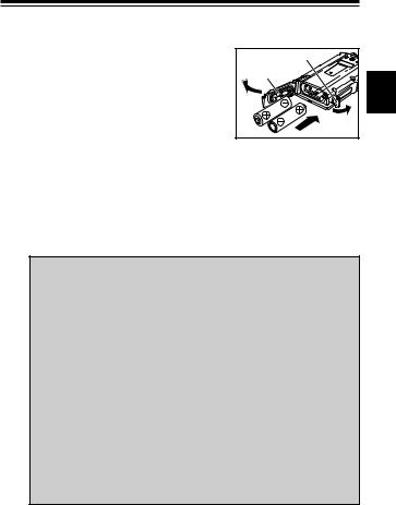
2-1 Attaching and Detaching Accessories
2 |
1. Hold the antenna by its base and turn it |
|
|
|
clockwise until it stops. |
|
Check to be sure the antenna is securely |
|
connected. |
|
2-1-1 Antenna( DJ-S45 T/E only) |
|
2. Turn the antenna counter-clockwise to |
|
detach it. |
|
Caution |
|
The DJ-S45 CQ takes fixed type antenna due to a legal |
|
requirement. NEVER try to detach it. |
2-1-2 Hand Strap
1.Attach the hand strap in the upper slot at the rear of the transceiver as shown in the illustration.
2-1-3 Belt Clip
1.Put the belt clip on the back of the transceiver.
2.Turn the screw clockwise until it stops. Check to be sure the clip is securely installed.
3.Turn the screw counter-clockwise to detach the belt clip.
Hand strap
Belt clip
7
2.Accessories
2-2 Setting Batteries
1.Open the cover latch and then open the cover.
2.Set two commercially available AA batteries in the +/- orientation marked at the internal front side.
3.Close the cover and then fix it with the cover latch.
Cover latch |
Cover |
2 |
2-3 Lithium Ion Battery Pack [EBP-60] (Option)
Please refer to the instruction manual that comes with the battery pack for operating and charging procedures.
 Caution
•Manganese batteries are not recommended as they may decrease the transmission output level.
•Be sure to observe proper orientation of the batteries polarity (+/-).
•Latest generation dry cells such as "Oxiride" batteries can be used.
•Ni-MH rechargeable cells are also usable. Please carefully read instructions of its manufacturer to properly use them. •Regardless of the type of battery you use, please:
1.Never mix the type, brand, or different status of use. 2.Never remove protective materials around cells. 3.Clean the contacts with a dry cloth once in a while to
obtain best performance.
4.Respect all the instructions given by battery manufacturer for safe and proper use.
8

2.Accessories
2-4 |
Battery Level Indicator |
|
|
|
|
|
|
•Battery consumption level may change |
|
|
|
|
|
depending on the surrounding temperature |
|
|
|
2 |
|
|
|
|
|
|
or the frequency of use. |
|
|
|
|
|
•Even if the battery icon appears to indicate |
Battery icon |
|
|
|
|
|
||||
|
|
the necessity of charging the battery, it can |
*When the battery level |
||
|
|
be used further if the usage is only for low |
becomes low, the battery icon |
||
|
|
appears. |
|||
output transmission or reception. |
Charge or replace the battery. |
|
•The default setting of the battery pack type is "bAt-1" which is for AA type cells. When using Lithium Ion battery pack, select the battery type setting to "bAt-2" in the Setting mode (page 26, ITEM No.16) to correctly indicate the battery level icon.
Reference : Due to the amplification circuitry used in this unit to obtain high output with only 2 batteries, it may happen that the unit cannot be turned on when the battery voltage is getting low (while the low-battery icon is on the display), but not completely discharged yet. This is not a defect but we recommend that:
•When the low-battery icon appears, recharge or replace the batteries.
•When the low-battery icon appears, try not to turn off the radio until fully use up the battery power.
When they are completely discharged the display will turn off.
9
3.Control Functions
3. Control Functions
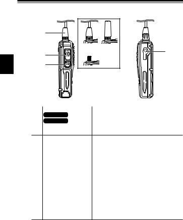
3-1 Names and Operations of the Transceiver Controls
■ Top and Front Views
|
|
|
|
|
|
|
3 |
|
|
|
|
|
|
|
|
|
|
|
|
|
|
|
|
|
|
|
|
|
|
|
|
No. |
Name |
Functions |
|
Power/Volume Dial |
Switches power ON/OFF, and also adjusts |
|
|
|
|
the audio volume. |
|
MIC Connector |
For connection of the optional external |
|
|
|
|
microphone (2k Ω) with 2.5 ø stereo plug. |
|
SP Connector |
For connection of the optional external |
|
|
|
|
speaker(8 Ω) with 3.5 ø monophonic plug. |
|
RX/TX Lamp |
Illuminates green when the squelch opens |
|
|
|
|
and red when transmitting. |
|
Speaker |
|
A thin speaker is built in. |
|
F key |
|
Use this key in combination with other keys to |
|
|
|
access various functions of the transceiver. |
|
|
|
Holding this key for 2 seconds activates the |
|
|
|
Setting mode where various settings are |
|
|
|
possible. |
|
Display (LCD) |
Refer to "Display" in this manual (page 14). |
|
|
Keypad |
|
Refer to "Key Operations" (page 12). |
|
Microphone |
Speak into microphone from a distance of |
|
|
|
|
approx. 5cm at normal tone of voice. |
|
10
3.Control Functions
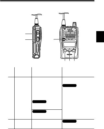
■ Side Views
|
|
|
|
|
|
3 |
|
|
|
|
|
|
|
|
Antenna side |
Dial side |
|
|
|
No. |
Name |
Functions |
DJ-S45 CQ |
Undetachable fixed type antenna. |
|
DJ-S45 T/E |
Install the included antenna. Choose an |
|
SMA Antenna Connector antenna which has low SWR (standing Wave
Ratio) if you purchase one.
PTT (press to talk) key |
While this key is held down, the transceiver |
|
|
transmits. When the key is released, |
the |
|
transceiver returns to the receive mode. |
|
MONI key |
When this key is pressed, the squelch opens |
|
|
and you can hear received signals. |
The |
|
squelch also opens when the tone squelch is |
|
|
set. If this key is pressed while "F" appears, |
|
|
the Key Lock function is activated. Pressing |
|
|
this key, while the PTT key is pressed and |
|
|
held, transmits the tone call signal. |
|
DC-IN |
Terminal for connecting an external power |
|
|
supply. Connect the optional cigarette lighter |
|
|
cable EDH-33 for mobile operation. Use a |
|
|
stable power supply with 3.0~6.0VDC, with a |
|
|
capacity of 2A or more. |
|
11
3.Control Functions
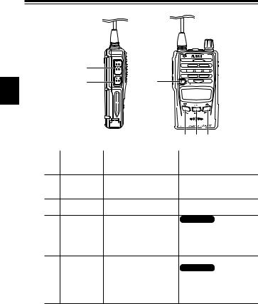
3-2 Key Operations
|
|
3 |
|
|
|
|
|
|
|
|
No. Name |
Independent operation |
After pressing F key |
PTT |
Transmits or completes the |
|
setting in the Setting mode.
MONI |
Activates |
the monitoring |
Switches the key lock |
|
function. |
|
ON/OFF (page 34). |
F/SET |
Accesses Various functions. |
DJ-S45 T/E |
|
|
|
|
Adjusts the frequency in |
|
|
|
1MHz step(page 17). |
▼/T SQL |
Decreases the frequency |
Sets the tone squelch function |
|
|
and memory channels. |
(page 36~38). |
|
V/M / MW |
DJ-S45 T/E |
Programs memory channels |
|
|
Switches |
VFO/Memory |
(page 18). |
modes.
DJ-S45 CQ
Switches LPD (VFO)/PMR/
Memory modes.
▲/RPT |
Increases the frequency |
DJ-S45 T/E |
|
and memory channels. |
Sets the repeater functions |
|
|
(page 33~34). |
12
3.Control Functions
|
|
3
|
|
|
|
|
|
No. Name |
Pressed for a while |
During transmission |
PTT |
Enables transmission while |
|
holding.
MONI |
Activates the monitor Transmits tone call signal |
operation while holding (page 21).
(page 21).
F |
Activates the Setting mode |
(page 28).
▼/T SQL |
Pressed shorter than 2 sec., DJ-S45 T/E |
starts downward scanning, Sets the transmission output
and pressed longer than 2 level low (page 22).
sec., decreases the value
continuously (page 30~33).
V/M / MW |
|
|
▲/RPT |
Pressed shorter than 2 sec., |
DJ-S45 T/E |
|
starts upward scanning, |
Sets the transmission output |
|
and pressed longer than 2 |
level high (page 22). |
|
sec., increases the value |
|
|
continuously (page 30~33). |
|
13
|
|
|
|
|
|
|
|
|
|
|
|
|
|
|
|
|
|
|
|
|
|
|
|
|
3.Control Functions |
|
|||||
|
|
|
|
|
|
|
|
|
|
|
|
|
|
|
|
|
|
|
|
|
|
|
|
|
|
|
|
|
|
||
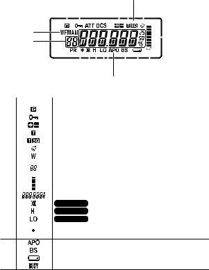
3-3 Display |
|
|
|
|
|
|
|
|
|
|
|
|
|
|
|
|
|
|
|
|
|
|
|
|
|
|
|
|
|
||
|
|
|
|
|
|
|
|
|
|||||||||||||||||||||||
|
|
|
|
|
|
|
|
|
|
|
|
|
|
|
|
|
|
|
|
|
|
|
|||||||||
|
|
|
|
|
|
|
|
|
|
|
|
|
|
|
|
|
|
|
|
|
|
|
|
|
|
|
|
|
|||
|
|
|
|
|
|
|
|
|
|
|
|
|
|
|
|
|
|
|
|
|
|
|
|
|
|
|
|||||
|
|
|
|
|
|
|
|
|
|
|
|
|
|
|
|
|
|
|
|
|
|
|
|
|
|
|
|||||
|
|
|
|
|
|
|
|
|
|
|
|
|
|
|
|
|
|
|
|
|
|
|
|
|
|
3 |
|||||
|
|
|
|
|
|
|
|
|
|
|
|
|
|
|
|
|
|
|
|
|
|
|
|
|
|
|
|||||
|
|
|
|
|
|
|
|
|
|
|
|
|
|
|
|
|
|
|
|
|
|
|
|
|
|
|
|
|
|||
|
|
|
|
|
|
|
|
|
|
|
|
|
|
|
|
|
|
|
|
|
|
|
|
|
|
|
|
|
|
||
|
|
|
|
|
|
|
|
|
|
|
|
|
|
|
|
|
|
|
|
|
|
|
|
|
|
|
|
|
|
|
|
|
|
|
|
|
|
|
|
|
|
|
|
|
|
|
|
|
|
|
|
|
|
|
|
|
|||||||
|
|
|
|
|
|
|
|
|
|
|
|
|
|
|
|
|
|
|
|
|
|
|
|
|
|
|
|
|
|
|
|
|
|
|
|
|
|
|
|
|
|
|
|
|
|
|
|
|
|
|
|
|
|
|
|
||||||||
|
|
|
|
|
|
|
|
|
|
|
|||||||||||||||||||||
|
|
|
|
|
|
|
|
|
|
|
|
|
|
|
|
|
|
|
|
|
|
|
|
|
|
|
|
|
|
|
|
|
No. Name |
|
|
|
|
|
|
|
|
|
|
Indication |
|
|
|
||||||||||||||||
|
|
Appears when the F key is pressed. |
|
|
|
||||||||||||||||||||||||||
|
|
Appears when keys are locked. |
|
|
|
||||||||||||||||||||||||||
|
|
Indicates the shift (+/-) direction. |
|
|
|
||||||||||||||||||||||||||
|
|
Appears when the tone encode (ENC) is set. |
|
|
|
||||||||||||||||||||||||||
|
|
Appears when the tone squelch is set. |
|
|
|
||||||||||||||||||||||||||
|
|
Appears when the bell function is ON. |
|
|
|
||||||||||||||||||||||||||
|
|
Blinks during memory writing mode. |
|
|
|
||||||||||||||||||||||||||
|
|
Indicates memory No. in the Memory mode and setting |
|
|
|
||||||||||||||||||||||||||
|
|
No. in the Setting mode. |
|
||||||||||||||||||||||||||||
|
|
Indicates the receiving level and the transmission output. |
|
|
|
||||||||||||||||||||||||||
|
|
|
|
|
|
|
|
|
|
|
|
|
|
|
|
|
|
|
|
|
|
|
|
|
|
|
|
|
|
|
|
|
|
Indicates the frequency and various setting status. |
|
|
|
||||||||||||||||||||||||||
|
|
DJ-S45 T/E Appears when the repeater function is set. |
|
|
|
||||||||||||||||||||||||||
|
|
|
DJ-S45 T/E |
Appears when transmission output level is high. |
|
|
|
||||||||||||||||||||||||
|
|
|
|
|
|
|
|
|
|
|
|
|
|
|
|
|
|
|
|
|
|
|
|
|
|
|
|
|
|
|
|
|
|
DJ-S45 T/E |
Appears when transmission output level is low. |
|
|
|
|||||||||||||||||||||||||
|
|
Divides MHz and kHz of the frequency. Blinks during |
|
|
|
||||||||||||||||||||||||||
scanning operation.
|
Appears while the Auto-Power-Off function is ON. |
|
Appears while the Battery-Save function is ON. |
|
Appears when the remaining battery level is low. |
|
Appears when the squelch opens. |
*Unexplained icons are not used on this transceiver.
14
 Loading...