


ALL MODE HF TRANSCEIVER
DX-SR8
Instruction Manual
ALINCO,INC.
Head Office: Yodoyabashi-Dai Building 13th Floor
4-9, 4-Chome, Koraibashi, Chuo-ku, Osaka 541-0043, Japan Phone: +81-6-7636-2362 Fax: +81-6-6208-3802 http://www.alinco.com/
E-mail: export@alinco.co.jp
Thank you for purchasing your new ALINCO transceiver.
This instruction manual (and addendum sheets) contains important safety and operating instructions.
Please read this manual carefully before using the product and keep it for future reference.
Printed in Japan
Copyright Alinco, Inc. PS0610
FNNM-EN

NOTICE / Compliance Information Statement
Conformity Information
Alinco, Inc. Electronics Division hereby declares on our sole responsibility that the product(s) listed below comply with the essential requirements of the Directive 1999/5/EC, The council of 3/9/99 on Radio Equipment and Tlecommunication Terminal Equipment and the mutual recognition of their conformity and with the provisions of Annex, after having performed the required measurements at Notified Bodies per Standards, and relative certificate(s) or document(s) can be reviewed at http://www.alinco.com/Ce/ .
DX-SR8E
SSB/CW/FM/AM HF TRANSCEIVER
European amateur radio bands between 1.8 MHz - 29 MHz as per specifications on page 94.
This device is authorized for use in all Eu and EFTA memeber states. An operator's license is required for this device.
Check with your local waste officals for details on recycling or proper disposal in your area.
RoHS
HF Transceiver DX-SR8T
The FCC Part 15 approval is not required for amateur-radio use of this device in USA/Canada.
Copyright © All rights reserved. No part of this document may be reproduced, translated or transcribed in any form or by any means without the prior permission of Alinco. Inc., Osaka, Japan, English Edition Printed in Japan.

Contents
Contents ........................................................................................... |
|
1 |
WARNING ......................................................................................... |
|
5 |
ALERT.................................................................................................................... |
|
5 |
Environment and condition of use:......................................................... |
5 |
|
Handling this product: ............................................................................ |
6 |
|
About power-supply: .............................................................................. |
6 |
|
In case of emergency: ............................................................................... |
7 |
|
Maintenance .......................................................................................... |
7 |
|
CAUTION ............................................................................................................... |
|
7 |
Environment and condition of use:......................................................... |
7 |
|
About transceiver ................................................................................... |
8 |
|
About power-supply ............................................................................... |
8 |
|
Before Operating the Transceiver .................................................. |
9 |
|
Attention ................................................................................................................. |
|
9 |
Notice to California resident users ............................................................ |
9 |
|
The transceiver has no protection against lightning. ................................. |
9 |
|
Limited Power Source................................................................................ |
9 |
|
Introduction.................................................................................... |
10 |
|
Chapter 1 |
Getting Started .......................................................... |
11 |
1.1 Features ......................................................................................................... |
11 |
|
DX-SR8 Features .................................................................................... |
11 |
|
1.2 Standard Accessories .................................................................................... |
12 |
|
Checking Accessories ............................................................................. |
12 |
|
1.3 Installation and Connection (For Base Station).............................................. |
13 |
|
Connection Diagram................................................................................ |
13 |
|
Procedure................................................................................................ |
13 |
|
1.4 Installation and Connection (For Mobile Operation)....................................... |
16 |
|
Connection Diagram................................................................................ |
16 |
|
Procedure................................................................................................ |
16 |
|
1.5 Controls, Connectors, and Display................................................................. |
18 |
|
Front Panel .............................................................................................. |
18 |
|
Front Panel (keypad) ............................................................................... |
19 |
|
Rear Panel............................................................................................... |
21 |
|
Microphone.............................................................................................. |
22 |
|
Display..................................................................................................... |
23 |
|
Chapter 2 |
Communications ....................................................... |
25 |
2.1 Reception Basics ........................................................................................... |
25 |
|
Introduction.............................................................................................. |
25 |
|
Procedure................................................................................................ |
25 |
|
Exercise................................................................................................... |
29 |
|
Direct Frequency Entry with Keypad ....................................................... |
30 |
|
Getting Familiar with Useful Functions .................................................... |
31 |
|
2.2 Transmission Basics....................................................................................... |
33 |
|
Introduction.............................................................................................. |
33 |
|
Procedure................................................................................................ |
33 |
|
2.3 SSB Operation ............................................................................................... |
35 |
|
Introduction.............................................................................................. |
35 |
|
1

Contents
|
Procedure................................................................................................ |
35 |
2.4 |
Practical Techniques for SSB Operation ........................................................ |
36 |
|
Introduction.............................................................................................. |
36 |
|
Eliminating Interference (QRM) ............................................................... |
36 |
|
Communicating in Bad Conditions .......................................................... |
37 |
|
Communicating with Off-frequency Stations ........................................... |
37 |
|
Communicating in Pile-ups...................................................................... |
37 |
2.5 |
AM Operation ................................................................................................. |
38 |
|
Procedure................................................................................................ |
38 |
2.6 |
General Coverage Receiver Operation .......................................................... |
39 |
|
Introducution............................................................................................ |
39 |
|
Procedure................................................................................................ |
39 |
2.7 |
FM Operation ................................................................................................. |
41 |
|
Introduction.............................................................................................. |
41 |
|
Procedure................................................................................................ |
41 |
2.8 |
Repeater Operation (QUICK OFFSET).......................................................... |
42 |
|
Introduction.............................................................................................. |
42 |
|
Procedure................................................................................................ |
42 |
2.9 |
CW Operation ................................................................................................ |
43 |
|
Introduction.............................................................................................. |
43 |
|
Procedure................................................................................................ |
43 |
2.10 Practical Techniques for CW Operation........................................................ |
44 |
|
|
Introduction.............................................................................................. |
44 |
|
Reducing Interference ............................................................................. |
44 |
|
Communicating in Bad Conditions .......................................................... |
44 |
|
Communicating in Pile-ups...................................................................... |
44 |
2.11 Split-Frequency Operation ........................................................................... |
45 |
|
|
Introduction.............................................................................................. |
45 |
|
Procedure................................................................................................ |
45 |
2.12 RTTY Packet Operation (FAX/SSTV) ........................................................... |
46 |
|
|
Introduction.............................................................................................. |
46 |
|
Connecting Additional Equipment ........................................................... |
46 |
|
Procedure................................................................................................ |
46 |
Chapter 3 Memory Features....................................................... |
47 |
|
3.1 |
Basics............................................................................................................. |
47 |
|
Features .................................................................................................. |
47 |
3.2 |
Simplex-VFO-Frequency Programming ......................................................... |
48 |
|
Procedure................................................................................................ |
48 |
3.3 |
Split-Frequency Programming Using Quick Offset Function .......................... |
49 |
|
Procedure................................................................................................ |
49 |
3.4 |
Split-frequency Programming......................................................................... |
50 |
|
Procedure................................................................................................ |
50 |
3.5 |
Memory Mode Operation ............................................................................... |
51 |
|
Procedure................................................................................................ |
51 |
3.6 |
Memory Channel Data Erasing ...................................................................... |
52 |
|
Erasing Data in a Selected Memory Channel ......................................... |
52 |
|
Erasing All Memory Channels (Memory reset) ....................................... |
52 |
3.7 |
Memory To VFO Data Transfer ....................................................................... |
53 |
|
Introduction.............................................................................................. |
53 |
|
Procedure................................................................................................ |
53 |
3.7 |
Channel Name (Alphanumeric) Registration Function................................... |
53 |
2

Contents
Chapter 4 |
Scann i ng .................................................................... |
55 |
4.1 Basics |
............................................................................................................. |
55 |
Introduction.............................................................................................. |
55 |
|
Scan ..............................................................................................Types |
55 |
|
Scanning ................................................................................conditions |
57 |
|
4.2 Band Scan...................................................................................................... |
58 |
|
4.3 Programmed .........................................................................................Scan |
59 |
|
4.4 Search ...................................................................................................Scan |
59 |
|
4.5 Memory .................................................................................................Scan |
60 |
|
4.6 Skip-channel ......................................................................................Setting |
60 |
|
4.7 Priority ...................................................................................................Scan |
61 |
|
Chapter 5 ...................................................... |
Spec i al Funct i ons |
62 |
5.1 Interference ....................................................................................Reducers |
62 |
|
Introduction.............................................................................................. |
62 |
|
IF ..................................................................................................SHIFT |
62 |
|
Narrow ............................................................................................Filter |
63 |
|
CW ................................................................................BFO REVERSE |
64 |
|
NB ..................................................................................(Noise Blanker) |
64 |
|
5.2 Other Useful ..................................................................................Functions |
65 |
|
RIT/TXIT ...................................................................................Function |
65 |
|
±' ...........................................................f (Plus-Minus Delta F) Function |
66 |
|
VFO ..................................................................................A=B Function |
66 |
|
MULTI .....................................................................FUNCTION Feature |
67 |
|
DIAL ...............................................................................LOCK Function |
68 |
|
KEY ................................................................................LOCK Function |
68 |
|
CABLE .......................................................................................CLONE |
69 |
|
Chapter 6 ........................Parameter Setting Mode (Set mode) |
70 |
|
A List of the .................................................................Setting Mode Parameters |
70 |
|
To Use the ....................................................................Parameter Setting Mode |
70 |
|
Menu 00. Frequency ...........................................Step of the [c/d] Keys Setting |
71 |
|
• SSB .............................................................................and CW Modes |
71 |
|
• AM ...............................................................................................Mode |
71 |
|
• FM ...............................................................................................Mode |
72 |
|
Menu 01. Memory ...............................................................Overwrite Protection |
72 |
|
Menu 02. Memory .................................................Frequency Access Protection |
73 |
|
Menu 03. Timer .............................................................................SCAN Setting |
73 |
|
Menu 04. Select .................................................................................Scan types |
74 |
|
Menu 05. Search ..................................................range setting for Search scan |
75 |
|
Menu 06. Memory ....................................................................scan skip Setting |
75 |
|
Menu 07. Dimmer................................................................................................. |
76 |
|
Menu 08. Beep ..........................................................................................Sound |
76 |
|
Menu 09. Automatic ..............................................................USB/LSB Selection |
77 |
|
Menu 10. Automatic .....................................................AGC-S/AGC-F Selection |
77 |
|
Menu 11. TXIT ...........................................................................Function Setting |
78 |
|
Menu 12. Electronic .......................................................................Keyer Setting |
78 |
|
Menu 13. Electronic ............................................................Keyer Speed Setting |
78 |
|
Menu 14. Electronic .........................................................Keyer Reverse Setting |
79 |
|
Menu 15. Sidetone ...............................................................(CW Offset) Setting |
79 |
|
Menu 16. Break .................................................-in Delay Time for CW operation |
79 |
|
• AT .............................................................................................(AUTO) |
80 |
|
3

Contents
• 1 to 7 ..................................................................................................... |
80 |
• FL (FULL).............................................................................................. |
80 |
Menu 17. Key ratio ............................................................................................... |
80 |
Menu 18. CTCSS Tone Encoding Setting ............................................................ |
81 |
Menu 19. Speech Compressor............................................................................. |
81 |
Menu 20. PTT Key Lock ....................................................................................... |
82 |
Menu 21. APO-Auto Power OFF .......................................................................... |
82 |
MENU 22. UP/DOWN keys function setting ......................................................... |
83 |
MENU 23. FUNC key resume timing setting ........................................................ |
83 |
Chapter 7 Maintenance.............................................................. |
84 |
7.1 Adjustment ..................................................................................................... |
84 |
Introduction.............................................................................................. |
84 |
Adjustment Item List................................................................................ |
84 |
Removing the FRONT unit ...................................................................... |
84 |
Removing the Covers .............................................................................. |
84 |
Procedure................................................................................................ |
85 |
7.2 Fuse replacement .......................................................................................... |
86 |
DC POWER CABLE FUSE REPLACEMENT ......................................... |
86 |
CIRCUITRY FUSE REPLACEMENT....................................................... |
86 |
7.3 Reset.............................................................................................................. |
87 |
Procedure................................................................................................ |
87 |
7.4 Cleaning ......................................................................................................... |
87 |
7.5 Troubleshooting .............................................................................................. |
88 |
Appendix ........................................................................................ |
90 |
Options................................................................................................................. |
90 |
About Mounting Bracket and Carrying Handle ..................................................... |
91 |
External Antenna Tuner (Optional) ....................................................................... |
92 |
ALINCO EDX-2 ....................................................................................... |
92 |
Specifications ....................................................................................................... |
93 |
4

WARNING
To prevent any hazard during operation of Alinco’s radio product, in this manual and on the product you may find symbols shown below. Please read and understand the meanings of these symbols before starting to use the product.
Danger |
This symbol is intended to alert the user to an immediate danger that may |
|
cause loss of life and property if the user disregards the warning. |
||
|
||
|
|
|
Alert |
This symbol is intended to alert the user to a possible hazard that may cause |
|
loss of life and property if the user disregards the warning. |
||
|
||
|
|
|
Caution |
This symbol is intended to alert the user a possible hazard that may cause loss |
|
of property or injure the user if the warning is disregarded. |
||
|
||
|
|
Alert symbol. An explanation is given.
Warning symbol. An explanation is given.
Instruction symbol. An explanation is given.
 ALERT
ALERT
Environment and condition of use:
Do not drive while handling the radio for your safety. It is recommended that you check local traffic regulations regarding the use of radio equipment while driving.
Some countries prohibit the operation of transceiver while driving.
Do not use this product in close proximity to other electronics devices, especially medical ones. It may cause interference to those devices.
 Keep the radio out of the reach of children.
In case a liquid leaks from the product, do not touch it. It may damage your skin. Rinse with plenty of cold water if the liquid contacted your skin.
Never operate this product in facilities where radio products are prohibited for use such as aboard aircraft, in airports, in ports, within or near the operating area of business wireless stations or their relay stations.
Use of this product may be prohibited or illegal outside of your country. Be informed in advance when you travel.
The manufacturer declines any responsibilities against loss of life and/or property due to a failure of this product when used to perform important tasks like life-guarding, surveillance, and rescue.
Do not use multiple radios in very close proximity. It may cause interference and/or damage to the product(s).
5
WARNING
Risk of explosion if battery is replaced with an incorrect type.
Dispose of, or recycle used batteries according to your local regulations.
The manufacturer declines any responsibilities against loss of life and property due to a failure of this product when used with or as a part of a device made by third parties.
Use of third party accessory may result in damage to this product. It will void our warranty for repair.
Handling this product:
Be sure to reduce the audio output level to minimum before using an earphone or a headset. Excessive audio may damage hearing.
Do not open the unit without permission or instruction from the manufacturer. Unauthorized modification or repair may result in electric shock, fire and/or malfunction.
Do not operate this product in a wet place such as shower room. It may result in electric shock, fire and/or malfunction.
Do not place the product in a container carrying conductive materials, such as water or metal in close proximity to the product. A short-circuit to the product may result in electric shock, fire and/or malfunction.
Do not touch the heatsink (on/around the unit mostly found on mobile-base units) as it may become very hot during/after the operation that may risk burn your skin.
About power-supply:
 Use only appropriate, reliable power supply of correct voltage and capacity.
Do not connect cables in reverse polarity. It may result in electric shock, fire and/or malfunction.
Do not plug multiple devices including the power-supply into a single wall outlet. It may result in overheating and/or fire.
Do not handle a power-supply with a wet hand. It may result in electric shock.
Securely plug the power-supply to the wall outlet. Insecure installation may result in short-circuit, electronic shock and/or fire.
Do not plug the power-supply into the wall socket if the contacts are dirty. Shortcircuiting and/or overheating may result in fire, electric shock and/or damage to the product.
Do not modify or remove fuse-assembly from the DC-cable. It may result in fire, electric shock and/or damage to the product.
6
WARNING
In case of emergency:
In case of the following situation(s), please turn off the product, switch off the source of power, then remove or unplug the power-cord. Please contact your local dealer of this product for service and assistance. Do not use the product until the trouble is resolved. Do not try to troubleshoot the problem by yourself.
•When a strange sound, smoke and or strange odor comes out of the product.
•When the product is dropped or the case is broken or cracked.
•When a liquid penetrated inside.
•When a power-cord ( including DC-cables, AC-cables and adapters) is damaged.
For your safety, turn off then remove all related AC-lines to the product and its accessories from the wall outlet if a thunderstorm is likely.
Turn off the unit, remove the mobile antenna from its base and keep it in the vehicle if a thunderstorm is likely.
Please read cautions regarding the lightning-protection on page 7 also.
Maintenance
Do not open the unit and its accessories. Please consult with your local dealer of this product for service and assistance.
 CAUTION
Environment and condition of use:
Do not use the product in proximity to a TV or a radio. It may cause interference or receive interference.
Do not install in a humid, dusty or insufficiently ventilated place. It may result in electric shock, fire and/or malfunction.
Do not install in an unstable or vibrating position. It may result in electric shock, fire and/or malfunction when/if the product falls to the ground.
Do not install the product in proximity to a source of heat and humidity such as a heater or a stove. Avoid placing the unit in direct sunlight.
Do not modify, dismantle, incinerate, or immerse the batteries.
Please check your local regulations for details on recycling option or disposal of the batteries in your area.
7

WARNING
About transceiver
Do not connect devices other than specified ones to the jacks and ports on the product. It may result in damage to the devices.
Turn off and remove the power-source (AC cable, DC cable, battery, cigar-cable, charger adapter etc) from the product when the product is not in use for extended period of time or in case of maintenance.
Never pull the cord alone when you unplug AC cable from the wall outlet.
Use a clean, dry cloth to wipe off dirt and condensation from the surface of the product. Never use thinner or benzene for cleaning.
About power-supply
Use only reliable power supply of specific DC output range and be mindful of the polarity of the cables and DC jack.
Always turn off the power supply when connecting or disconnecting the cables.
When using an external antenna, make sure that the antenna ground is not common with the ground of the power supply.
European users: When a transceiver is powered from an external DC power source (adapter, power supply, cigar-plug etc), make sure that this power supply has approval to the level of IEC/EN 60950-1.
8
Before Operating the Transceiver
Attention
•Do not remove the case or touch the interior components. Tampering can cause equipment trouble.
•Do not use or keep the transceiver where it is exposed to direct sunlight, dusty places, or near sources of heat.
•Keep the transceiver away from TV’s or other equipment when it interferes with reception.
• When transmitting for long periods of time at high power, the transceiver might overheat.
•Turn the power off immediately if the transceiver emits smoke or strange odors. Ensure the transceiver is safe, then bring it to the nearest Alinco service center.
•An operator’s license is required for this device.
Notice to California resident users
The product that comes with this manual is free from dangerous material such as lead and cadmium as per RoHS order of EU.
The transceiver has no protection against lightning.
The user is responsible for providing adequate protection if he uses the device at home and installs the antenna outdoor. Be aware that any outdoor antenna creates a direct path for lighting current (more than 10kA) to the transceiver. This path exists whether the device is turned ON or OFF.
Any vehicle does not present a safe environment during lightning. This environment becomes much more dangerous if an outdoor antenna is installed on the car. Move the antenna and its cable into the car at the first sight of forthcoming thunderstorm and lightning.
Limited Power Source
Please note that the transceiver enclosure only provides mechanical protection for its internal parts; it will not contain a fire within the device if the fire starts under certain fault conditions. Alinco will not take responsibility for any fire hazard associated with powering the transceiver or charging its batteries using a power source that does not belong to the limited power source in the meaning of EN60950-1.
9

Introduction
Thank you very much for purchasing this excellent Alinco transceiver. Our products are ranked among the finest in the world. This radio has been manufactured with state of the art technology and it has been tested carefully at our factory. It is designed to operate to your satisfaction for many years under normal use.
PLEASE READ THIS MANUAL COMPLETELY TO LEARN ALL THE FUNCTIONS THE PRODUCT OFFERS. WE MADE EVERY ATTEMPT TO WRITE THIS MANUAL TO BE AS COMPREHENSIVE AND EASY TO UNDERSTAND AS POSSIBLE. IT IS IMPORTANT TO NOTE THAT SOME OF THE OPERATIONS MAY BE EXPLAINED IN RELATION TO INFORMATION IN PREVIOUS CHAPTERS. BY READING JUST ONE PART OF THE MANUAL, YOU RISK NOT UNDERSTANDING THE COMPLETE EXPLANATION OF THE FUNCTION.
10

Chapter 1 Getting Started
1.1 Features
DX-SR8 Features
DX-SR8
Covers HF (1.8 MHz to 28 MHz) amateur radio bands in SSB, AM, FM, and CW modes.
General coverage receiver
Covers 135 kHz to 30 MHz in all modes.
Direct frequency input
Provided with numerical keys to input frequency directly without using the dial.
Front control unit separation with the optional EDS-17
Completely detachable front control panel with large LCD.
Front speaker
Powerful and clear audio with 2 W Audio Amplifier.
Front jacks
Connecting easily with an external speaker and headphones.
Versatile interference eliminators
The IF SHIFT function; Built-in audio filter as standard for CW; and RF attenuator, all effectively help to reject unwanted signals.
Powerful CW operation with internal electronic keyer
Enables you to receive CW signals from either the upper or lower side of the carrier frequency.
Selectable sidetone and pitch, FULL BREAK-IN (QSK), SEMI BREAK-IN (7 steps), and AUTO BREAK-IN (delay time automatically adjusted with keying speed).
600 memory channels
A total of 600 channels can be registered in three banks: 200 channels per bank.
Each stores mode, filter, split frequencies, AGC, attenuator (or pre-amp), noise-blanker settings and more.
Computer control
The DX-SR8 can be controlled by a personal computer through the serial interface. Settings of frequency, mode, power, and memory channel can be controlled. (Optional PC interface cable required)
11
Chapter 1 Getting Started
1.2 Standard Accessories
Checking Accessories
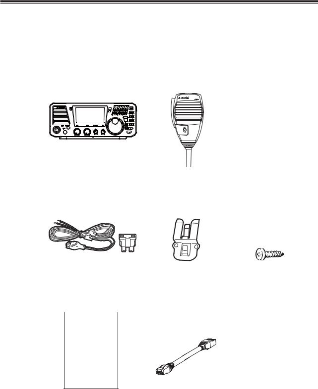
Carefully unpack to make sure the following items are found in the package.
• Transceiver |
|
|
• Microphone EMS-53 |
(DX-SR8) |
||
|
|
|
|
|
EMS-64 |
(DX-SR8T/E) |
|
|
|
|
|
|
|
|
|
|
|
|
|
|
|
|
|
|
|
|
|
• DC power cable with fuse |
• Mic Hanger Unit |
holder (UA0083) |
Mic Hanger (EBC-7) Tapping screws |
With spare fuses (2 pcs.) |
(M3.5×10 mm) 2pcs. |
|
(AJ0025) for EBC-7 |
(30A)
• Instruction manual |
[Spare-part / pre-installed] |
|
(PS0610) |
• Standard front unit cable used between main |
|
|
|
and front units. |
|
|
|
|
|
(UX1412) |
|
DX-SR8 |
|
Manual
The standard accessories may vary slightly depending on the version you have purchased. Please contact your local authorized Alinco dealer should you have any questions. ALINCO and authorized dealers are not responsible for any typographical errors there may be in this manual. Standard accessories may change without notice.
Warranty Policy:
Please refer to any enclosed warranty information or contact your authorized Alinco dealer/distributor for the warranty policy before purchase.
12
Chapter 1 Getting Started
1.3 Installation and Connection (For Base Station)
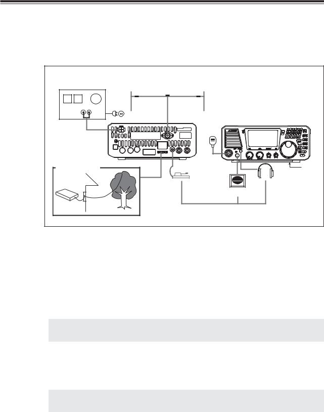
Connection Diagram
This diagram shows the connections for a base station.
13.8V DC regulated |
|
|
power supply |
HF band antenna |
|
|
Microphone |
|
EDX-2 (optional) |
|
Stand |
|
Key |
Headphone |
|
|
|
|
Speaker |
|
Long-wire |
|
|
antenna |
optional |
|
|
|
|
Procedure |
|
|
1. Connecting an antenna and ground cable
•Antenna connection
Use a properly-adjusted (low SWR) antenna to obtain optimum performance from the transceiver. A 50 ohm impedance coaxial with PL-259 connector is required for this connection.
NOTE: It is recommended to use an optional automatic antenna tuner (EDX-2) for proper
antenna matching.
•Ground connection
To prevent electric shock hazard and audio interference with other electronic appliances, bury a copper rod or plate under the ground and connect it to the transceiver GND terminal. Use a heavy gauge, short cable for this connection.
IMPORTANT: Do not ground the equipment on gas pipes, electrical conduits, or plastic
water pipes.
13
Chapter 1 Getting Started
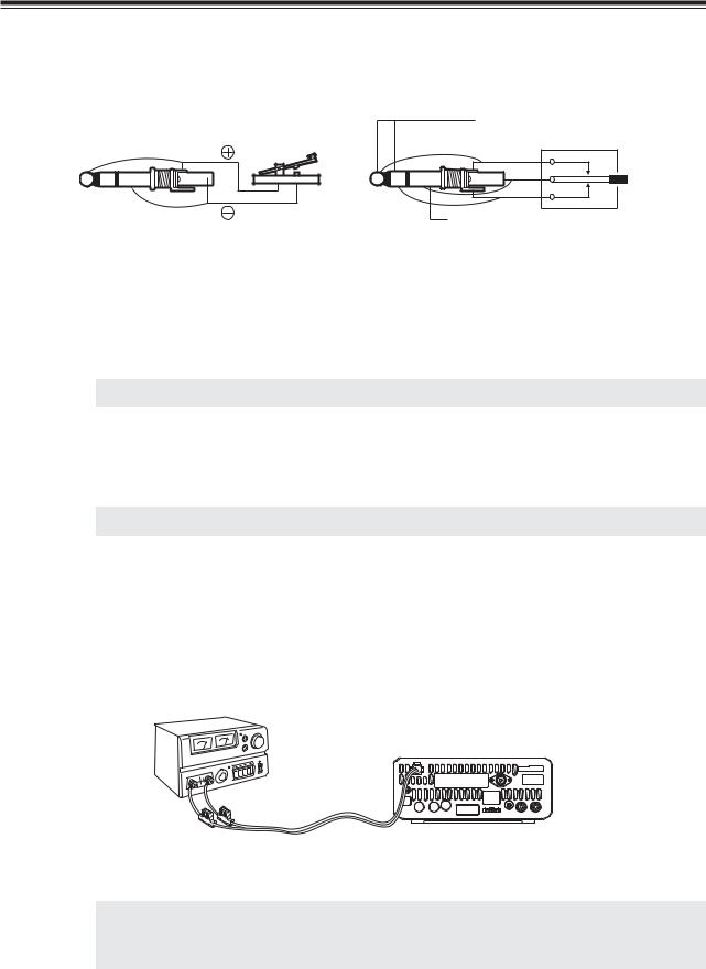
2. Connecting a telegraph key
Connect a 3.5 mm diameter stereo plug to the KEY jack on the rear panel. If using an electronic-keyer, pay attention to the polarity of the plug.
|
|
5V(+) |
|
|
Contact current: 1 to 2 mA |
( |
) |
(dash) |
|
|
(com) |
|
|
(dot) |
( |
) |
GND(-) |
|
|
|
When connecting a straight key |
When connecting a paddle |
|
3. Connecting an external speaker (if not using the internal speaker)
Connect a 3.5 mm diameter mono plug to the SPEAKER jack on the front panel. Use a 3 W or higher external speaker with 8 ohm impedance.
NOTE: When an external speaker is used, no sound is heard from the internal speaker.
4. Connecting headphones
Connect a 3.5 mm diameter mono or stereo plug to the PHONES jack on the front panel.
NOTE: When headphones are used, no sound is heard from the speaker.
5. Connecting a regulated DC power supply
The Transceiver requires a 12-13.8VDC negative grounded power source. Use a regulated power supply capable of providing continuous current of 30A or more. Power supplies that do not meet those specifications may cause malfunction and/or damage to the radio and will void the warranty. Alinco offers excellent communication-grade power supplies as optional accessories. Please contact your local authorized Alinco dealer.
*
Red to positive
Black to negative
IMPORTANT: Before connecting, be sure to turn off the transceiver and DC power supply.
*When a transceiver is powered from an external DC power source, make sure that this power supply has approval to the level of IEC/EN 60950-1.
14

Chapter 1 Getting Started
6. Installing the control panel and body separately
IMPORTANT: Be sure to disconnect the power cable before carrying out this procedure.
1. |
Remove 2 screws above the main unit to |
|
separate the front-control panel. Disconnect |
|
the cable |
2. |
Remove other 2 screws at the bottom of the |
|
main unit. |
3. |
Passing the separate-cable (5m) through the |
|
|
hole of the cover in advance, connect the |
|
|
cable to the main unit. |
|
|
|
4. |
Fix the cover to the main unit using those 4 |
|
screws. |
5. Fix the bracket using provided hardware, and connect another end of the cable to the front-control panel.
NOTE: Please be sure to keep the short, original cable in order to make it back to the original condition in future. Provided ferrite-beads on the separate cable are to eliminate the RF feed back. The position of beads may affect to the condition of RF feed back. See page 89 for troubleshooting.
15

Chapter 1 Getting Started
1.4 Installation and Connection (For Mobile Operation)
Connection Diagram
This diagram shows the connections for mobile operation.
DX-SR8
Co-ax
Control cable
Grounded Mobile whip antenna |
Grounded Mobile-base |
Automatic antenna tuner |
Single wire (Not Co-ax cable) |
EDX-2 (Options; see appendix-1)
Procedure
1. Installing an antenna
Use a properly-adjusted (low SWR) antenna to obtain optimum performance.
1. |
Secure a commercially-available antenna base in a proper position on your car. |
|
2. |
|
Ground the antenna base if necessary. |
|
|
|
|
|
IMPORTANT: A ground is indispensable for most HF antennas. |
|
|
Please refer to the instruction of the antenna before installation. |
3. |
|
|
|
Connect the antenna and transceiver using an appropreate cable that the antenna |
|
system requires.
IMPORTANT: After installing your antenna, ensure that you have the best possible SWR reading.
High RF environments can cause severe damage to your unit. Ensure that you are not in a high RF environment when operating the transceiver.
IMPORTANT: RF Hazard Warning
The electro-magnetic (radio Frequency) exposure level of this device may exceed the European standards of the hazard level when transmitting at the high-power setting while connected to a unity gain antenna at a distance of 63cm or less from the operator. Furthermore, the hazardous RF exposure level depends on the conditions of the combination of the antenna gain, distance from the operator, output setting and installation environment, therefore the operator may be exposed to stronger RF even at a distance of more than 63cm. For safety purpose, it is recommended that the antenna be installed outside of, and as far as possible from, the operator’s area. Avoid using an excessively high-gained antenna in case the distance between the operator and the antenna is very limited. Always use the minimum necessary output power for communications.
16
Chapter 1 Getting Started
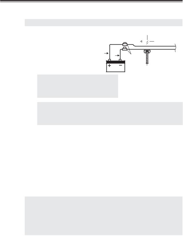
2. Connecting the power cable
IMPORTANT: Use a 12 V car battery to operate the transceiver.
1. |
Connect the supplied power cable directly to |
|
the car battery. |
Chassis
To engine room

 To passanger cabin
Red
Black
Fuse |
Transceiver |
Chassis
NOTE: If threading the cable through wiring holes, use grommets to prevent the cable from coming in contact with the car chassis.
IMPORTANT: • If using a 24 V car battery, be sure to convert the voltage to 12 V DC with a DC/DC converter.
•Never connect the power cable to a cigarette lighter connector because the available current is too low.
3. Connecting the accessories
Please refer to:
•Microphone, page 20
•Telegraph key, page 14
•External speaker, page 14
4. Installing the control panel and body separately (optional)
To detach the control panel from the body, refer to P.15.
Install the control panel in a location that is easily accessible using the separate angle bracket, and be sure as well to install the body in a proper location, such as under a seat.
IMPORTANT: • Be sure to disconnect the power cable before detaching the control panel
from the body.
•Give the first priority to the safety of driving. Do not install anything that could obstacle the controls of your vehicle in driver’s area.
•Mounting antenna and other accessories outside of your vehicle may be prohibited or restricted in some countries. Please check your local regulations before the installation.
17
Chapter 1 Getting Started
1.5 Controls, Connectors, and Display
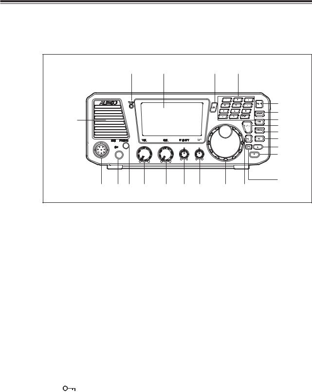
Front Panel
(22) |
(23) |
(12) |
(11) |
|
|
|
(1) |
|
|
|
(2) |
(21) |
(3) |
|
(4) |
|
(5) |
|
|
|
|
|
|
|
(7) |
|
|
|
|
|
|
|
(8) |
|
|
|
|
|
|
|
(9) |
|
|
|
|
|
|
|
(10) |
(20) |
(19) (18) |
(17) |
(16) |
(15) |
(14) |
(13) |
(6) |
No. |
Key |
|
Principal Function |
(1) |
POWER SWITCH |
Turns the power on/off. |
|
|
[PWR] |
|
|
(2) |
[MODE] key |
Press to select the USB, LSB, CWU, CWL, AM, or FM modes. |
|
(3) |
[V/M] key |
Switches between VFO mode and memory mode. |
|
(4) |
[FUNC] key |
Press and hold this key for 1 second to access the Set mode. |
|
(5) |
[M/KHz] key |
Switches the cursor position between MHz and kHz. |
|
(6) |
[RIT] key |
Press to turn the RIT or TXIT function on/off. |
|
(7) |
[RF] key |
Press to adjust receiver’s front-end gain by switching between the |
|
|
(preamplifier/attenuator) |
preamplifier and attenuator. Pressing this key will change gains |
|
|
|
|
as follows: +10 dB, 0 dB, -10 dB, and -20 dB. After pressing the |
|
|
|
[FUNC] key, press this key to select a narrow filter in the SSB, |
|
|
|
CW and AM mode. |
(8) |
[Ÿ] key |
Press to select memory channels and amateur radio bands, and to |
|
|
|
|
change frequency in 1 MHz and 100 kHz increments. Also used to |
|
|
|
select the transceiver’s settings in the Set mode. |
(9) |
[ź] key |
Press to select memory channels and amateur radio bands, and to |
|
|
|
|
change frequency in 1 MHz and 100 kHz decrements. Also used to |
|
|
|
select the transceiver’s settings in the Set mode. |
(10) |
[ |
] key |
Enables the dial and key locks. |
(11) |
KEYPAD |
The keypad can be used for several functions as described later. |
|
(12) |
MULTI FUNC [MF] key |
Press to access the multifunction. |
|
(13) |
MAIN tuning dial |
Rotate to select transmit/receive frequencies. |
|
(14) |
RIT control knob [RIT] |
Fine-tunes the reception frequency within a range of ±l.2 kHz. |
|
(15) |
IF SHIFT control knob |
Rotate to eliminate the interference by shifting the receiver IF pass |
|
|
[IF SHIFT] |
band (±1.5 kHz). |
|
(16) |
SQL control knob [SQL] |
Rotate to eliminate noise when no signal is received. |
|
(17) |
AF gain control knob |
Rotate to adjust audio level. |
|
|
[VOL] |
|
|
18
|
|
|
Chapter 1 Getting Started |
|
|
|
|
|
|
|
|
|
|
|
|
|
No. |
Key |
Principal Function |
(18) |
PHONE jack [PHONE] |
For connecting external headphones. Takes 8 to 32 ohm impedance |
|
|
|
|
headphones. |
(19) |
SPEAKER jack [SP] |
For connecting an external speaker. Takes 8 to 16 ohm impedance |
|
|
|
|
speakers. |
|
|
|
Connect optional ERW-4C or ERW-7 cable for PC-interface. |
(20) |
Microphone connector |
For connecting a microphone. |
|
|
|
[MIC] |
|
|
(21) |
Internal Speaker |
Received signals are heard from here. |
(22) |
TX/RX LED |
Lights red when transmitting the signal. |
|
|
|
|
Lights green when signals are received or squelch is open |
|
|
|
(unmuted). |
|
(23) |
LCD Display |
Shows operating and setting information. |
Front Panel (keypad)
(24) |
(25) |
(26) |
(27) |
(28) |
(29) |
(30) |
(31) |
(32) |
(33) |
(34) |
(35) |
|
|
|
|
|
|
|
|
|
|
No. |
Key |
Function |
||
(24) |
1 |
To recall 1.8 MHz Band (Freq. direct input 1) |
||
(25) |
2 |
To recall 3.5 MHz Band (Freq. direct input 2) |
||
(26) |
3 |
To recall 5.3 MHz Band* (Freq. direct input 3) |
||
(27) |
4 |
To recall 7 MHz Band (Freq. direct input 4) |
||
(28) |
5 |
To recall 10 MHz Band (Freq. direct input 5) |
||
(29) |
6 |
To recall 14 MHz Band (Freq. direct input 6) |
||
(30) |
7 |
To recall 18 MHz Band (Freq. direct input 7) |
||
(31) |
8 |
To recall 21 MHz Band (Freq. direct input 8) |
||
(32) |
9 |
To recall 24 MHz Band (Freq. direct input 9) |
||
(33) |
. |
Enters a frequency direct input 100 kHz (Freq. direct input decimal) |
||
(34) |
0 |
To recall 28 MHz Band (Freq. direct input 0) |
||
(35) |
ENT |
Enters a frequency direct input |
||
*5 channels allocated to the amateur-radio services can be transmitted on T version. Please refer Page 94 for details.
19
Chapter 1 Getting Started
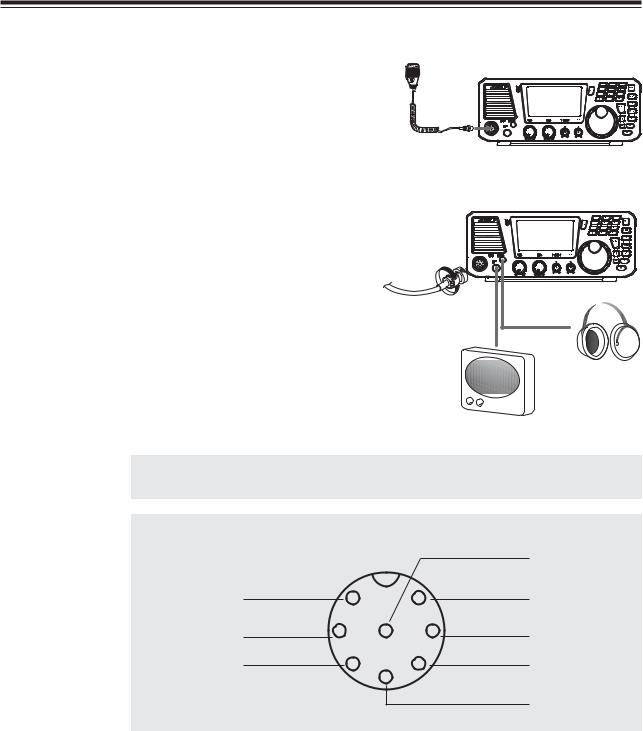
Connecting the Microphone
1. |
Plug the microphone into the microphone |
|
connector on the body. |
2. |
Tighten the screw on the connector to secure |
|
the connection. |
Microphone
Headphone
Speaker
NOTE: Please be sure that the connector is securely tightened, and check the
connection from time to time. Loose connection may cause noise on TX signals.
REFERENCE: Connector pin assignment
|
|
|
|
GND |
MIC |
1 |
|
7 |
MIC GND |
|
|
|
||
PTT |
2 |
8 |
6 |
NC |
DOWN |
3 |
|
5 |
DC 5V |
|
|
|
||
|
|
4 |
|
|
UP
(Front view)
20
Chapter 1 Getting Started
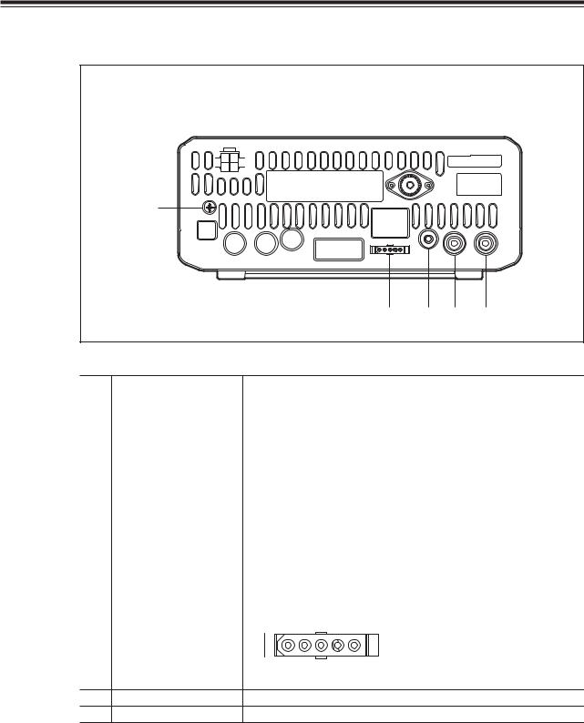
Rear Panel
|
|
|
(6) |
|
(1) |
||||||
|
|
|
|
|
|
|
|
|
|
|
|
|
|
|
|
|
|
|
|
|
|
|
|
(7)
(5) |
(4) |
(3) |
(2) |
No. |
Key |
Function |
|||||||||||
(1) |
ANTENNA connector |
For connecting an HF band antenna. Takes a 50 ohm impedance |
|||||||||||
|
|
coaxial cable with PL-259 connector. |
|||||||||||
(2) |
RELAY (external relay) |
For connecting external equipment such as a linear amplifier for |
|||||||||||
|
jack |
switching between reception and transmission. Takes a phono- |
|||||||||||
|
|
plug. |
|||||||||||
(3) |
External ALC input jack |
For connecting the phono-plug from the amplifier ALC circuit |
|||||||||||
|
|
when a linear amplifier is used. The ALC input voltage must be |
|||||||||||
|
|
from 0 to -3 V DC. |
|||||||||||
(4) |
CW-KEY jack |
For connecting a telegraph key or manipular paddle for internal |
|||||||||||
|
|
electronic-keyer |
|||||||||||
(5) |
ACC (accessory) |
For connecting optional EDX - 2 antenna tuner. |
|||||||||||
|
connector |
|
[Pin configuration] |
||||||||||
|
|
|
|||||||||||
|
|
TUNE1 TUNE2 13.8VDC (1A) |
|||||||||||
|
|
|
|
|
|
|
|
|
|
|
|
|
|
|
|
|
|
|
|
|
|
|
|
|
|
|
|
|
|
|
|
|
|
|
|
|
|
|
|
|
|
|
|
|
|
|
|
|
|
|
|
|
|
|
|
|
|
|
|
|
|
|
|
|
|
|
|
|
|
TKEY GND
For connecting the supplied DC power cable.
For connecting a ground cable.
21

Chapter 1 Getting Started
Microphone
(2) (1)
(5); EMS-53
(3)
(5); EMS-64
(4)
No. |
Key |
Function |
(1) |
UP |
Increase the frequency, memory channel number, or setting |
|
|
channel. |
(2) |
DOWN |
Decrease the frequency, memory channel number, or setting |
|
|
channel. |
(3) |
PTT |
Press the [PTT (Push-To-Talk)] key to transmit. |
(4) |
Lock Switch |
Locks out the [UP] and [DOWN] keys. |
(5) |
MIC element |
Speak here during transmission. |
*The [UP/DOWN] keys of the microphone function as the [Ÿ/ź] keys of the control panel.
22

Chapter 1 Getting Started
Display |
|
|
|
|
|
(1) |
(3) |
(9) |
(5) |
(7) |
(8) |
(2) |
|
|
|
|
|
(4) |
|
|
|
|
(6) |
|
|
|
|
|
(10) |
(12) |
|
|
|
|
(14) |
(11) |
|
|
|
|
(16) |
(13) |
|
|
|
|
(15) |
(17) |
(18) |
|
|
(19) |
|
No. |
Key |
Function |
||||||||||||||||||||||||
(1) |
|
|
|
|
|
|
|
|
|
|
|
|
|
|
|
|
|
|
|
|
|
|
|
|
|
Appears in the MEMORY mode, indicating the selected memory |
|
|
|
|
|
|
|
|
|
|
|
|
|
|
|
|
|
|
|
|
|
|
|
|
|
|
channel. |
(2) |
|
|
|
|
|
|
|
|
|
|
|
|
|
|
|
|
|
|
|
|
|
|
|
|
|
Indicates the selected VFO mode A or B. |
|
|
|
|
|
|
|
|
|
|
|
|
|
|
|
|
|
|
|
|
|
|
|
|
|
|
|
(3) |
|
|
|
|
|
|
|
|
|
|
|
|
|
|
|
|
|
|
|
|
|
|
|
|
|
Appears while the external automatic antenna tuner is being |
|
|
|
|
|
|
|
|
|
|
|
|
|
|
|
|
|
|
|
|
|
|
|
|
|
|
tuned. |
(4) |
|
|
|
|
|
|
|
|
|
|
|
|
|
|
|
|
|
|
|
|
|
|
|
|
|
Appears in the split-frequency operation. |
|
|
|
|
|
|
|
|
|
|
|
|
|
|
|
|
|
|
|
|
|
|
|
|
|
||
|
|
|
|
|
|
|
|
|
|
|
|
|
|
|
|
|
|
|
|
|
|
|
|
|
|
|
(5) |
|
|
|
|
|
|
|
|
|
|
|
|
|
|
|
|
|
|
|
|
|
|
|
|
|
AGC parameter, S for slow, F for fast. |
|
|
|
|
|
|
|
|
|
|
|
|
|
|
|
|
|
|
|
|
|
|
|
|
|
|
(not in FM mode) |
(6) |
|
|
|
|
|
|
|
|
|
|
|
|
|
|
|
|
|
|
|
|
|
|
|
|
|
Indicates the receiver’s front-end gain or attenuation level. |
|
|
|
|
|
|
|
|
|
|
|
|
|
|
|
|
|
|
|
|
|
|
|
|
|
||
|
|
|
|
|
|
|
|
|
|
|
|
|
|
|
|
|
|
|
|
|
|
|
|
|
||
|
|
|
|
|
|
|
|
|
|
|
|
|
|
|
|
|
|
|
|
|
|
|
|
|
||
|
|
|
|
|
|
|
|
|
|
|
|
|
|
|
|
|
|
|
|
|
|
|
|
|
|
|
|
|
|
|
|
|
|
|
|
|
|
|
|
|
|
|
|
|
|
|
|
|
|
|
|
|
|
(7) |
|
|
|
|
|
|
|
|
|
|
|
|
|
|
|
|
|
|
|
|
|
|
|
|
|
Appears when a Multi-function key is activated. |
(8) |
|
|
|
|
|
|
|
|
|
|
|
|
|
|
|
|
|
|
|
|
|
|
|
|
|
Indicates the selected mode, including LSB, USB, CWL, CWU, |
|
|
|
|
|
|
|
|
|
|
|
|
|
|
|
|
|
|
|
|
|
|
|
|
|
|
FM, AM and SET. |
(9) |
|
|
|
|
|
|
|
|
|
|
|
|
|
|
|
|
|
|
|
|
|
|
|
|
|
This cursor notifies of the position you can change using the [M/ |
|
|
|
|
|
|
|
|
|
|
|
|
|
|
|
|
|
|
|
|
|
|
|
|
|
|
KHz] key. |
|
|
|
|
|
|
|
|
|
|
|
|
|
|
|
|
|
|
|
|
|
|
|
|
|
|
Appears above the frequency digit you can change with the [UP/ |
|
|
|
|
|
|
|
|
|
|
|
|
|
|
|
|
|
|
|
|
|
|
|
|
|
|
DOWN] or [Ÿ/ź] keys. |
(10) |
|
|
|
|
|
|
|
|
|
|
|
|
|
|
|
|
|
|
|
|
|
|
|
|
|
Indicates the transmit/receive frequency. |
|
|
|
|
|
|
|
|
|
|
|
|
|
|
|
|
|
|
|
|
|
|
|
|
|
|
|
(11) |
|
|
|
|
|
|
|
|
|
|
|
|
|
|
|
|
|
|
|
|
|
|
|
|
|
Appears when a function key is activated. |
(12) |
|
|
|
|
|
|
|
|
|
|
|
|
|
|
|
|
|
|
|
|
|
|
|
|
|
Appears when the DIAL or key LOCK function is activated. |
(13) |
|
|
|
|
|
|
|
|
|
|
|
|
|
|
|
|
|
|
|
|
|
|
|
|
|
“LOW” appears when the output power is set to low. |
|
|
|
|
|
|
|
|
|
|
|
|
|
|
|
|
|
|
|
|
|
|
|
|
|
||
|
|
|
|
|
|
|
|
|
|
|
|
|
|
|
|
|
|
|
|
|
|
|
|
|
|
“S-LOW” appears when the output power is set to supper low. |
(14) |
|
|
|
|
|
|
|
|
|
|
|
|
|
|
|
|
|
|
|
|
|
|
|
|
|
Appears when the NB (noise blanker) is activated. |
(15) |
|
|
|
|
|
|
|
|
|
|
|
|
|
|
|
|
|
|
|
|
|
|
|
|
|
Appears when the narrow filter is used in the SSB, CW and AM |
|
|
|
|
|
|
|
|
|
|
|
|
|
|
|
|
|
|
|
|
|
|
|
|
|
|
modes. |
(16) |
|
|
|
|
|
|
|
|
|
|
|
|
|
|
|
|
|
|
|
|
|
|
|
|
|
Appears during the tone encode operation. (FM mode only) |
(17) |
|
|
|
|
|
|
|
|
|
|
|
|
|
|
|
|
|
|
|
|
|
|
|
|
|
Appears when squelch is unmuted. |
(18) |
|
|
|
|
|
|
|
|
|
|
|
|
|
|
|
|
|
|
|
|
|
|
|
|
|
S meter: Indicates relative received signal strength |
|
|
|
|
|
|
|
|
|
|
|
|
|
|
|
|
|
|
|
|
|
|
|
|
|
|
RF meter: Indicates relative output power level. |
|
|
|
|
|
|
|
|
|
|
|
|
|
|
|
|
|
|
|
|
|
|
|
|
|
|
|
(19) |
|
|
|
|
|
|
|
|
|
|
|
|
|
|
|
|
|
|
|
|
|
|
|
|
|
Indicates the TXIT or RIT shift frequency. |
|
|
|
|
|
|
|
|
|
|
|
|
|
|
|
|
|
|
|
|
|
|
|
|
|
||
|
|
|
|
|
|
|
|
|
|
|
|
|
|
|
|
|
|
|
|
|
|
|
|
|
|
|
|
|
|
|
|
|
|
|
|
|
|
|
|
|
|
|
|
|
|
|
|
|
|
|
|
|
|
|
|
|
|
|
|
|
|
|
|
|
|
|
|
|
|
|
|
|
|
|
|
|
|
|
|
|
23

Chapter 1 Getting Started
Quick Reference of Control keys
There are 3 types of key operations; simply press it, press it after [FUNC] key, or press and hold it for more than 1 second (*).
NOTE: |
FUNC + this key: Press [FUNC] key, then press this key. |
|
|
(P.xx) refers to the page this operation is mentioned in this manual. |
|
|
|
|
|
|
|
|
This key only |
FUNC + this key (See NOTE) |
FUNC |
Accesses the FUNC mode. |
– |
|
* Accesses Parameter setting mode. (P.70) |
|
V/M |
Switches between VFO Mode and Memory Mode. |
Switches to memory bank. |
|
* Activates VFO A = B function (P.66) |
* Program memory channels. |
M/KHz |
Changes cursor position for setting band/ |
Switches between AGC-S and AGC-F. |
|
memory/frequency with [UP/DOWN] keys. |
|
|
(P.27) |
|
MODE |
Selects the USB, LSB, CWU, CWL, AM, |
Switches between UT and LT. (P.46) |
|
FM modes. |
|
|
* The mode UP/DOWN operation is |
|
|
available. (P.26) |
|
RF |
Changes RF gain. |
Switches between narrow filter ON/OFF. |
|
* Monitors transmit frequency. (P.45) |
(P.64) |
LOCK |
Locks main dial tuning. (P.68) |
Locks keys and main dial tuning. (P.68) |
MULTI |
Accesses the Multifunction. (P.67) |
The allotment setting of the [MULTI] key. |
Ÿ |
UP of MHz, kHz, BAND and Memory. |
– |
|
* Changes automatically while the key is |
|
|
pressed. |
|
ź |
DOWN of MHz, kHz, BAND and Memory. |
– |
|
* Changes automatically while the key is |
|
|
pressed. |
|
RIT |
Switches TXIT/RIT function ON/OFF. (P.65) |
±'f function of TXIT/RIT. (P.66) |
1 |
To recall the 1.8 MHz BAND. |
Switches between VFO A and VFO B. |
|
Frequency direct input “1”. |
Switches between memories bank A, B and blank. |
2 |
To recall the 3.5 MHz BAND. |
Transfers memory to VFO. (P.53) |
|
Frequency direct input “2”. |
|
3 |
To recall the 5.3 MHz BAND. |
Erases memory channel. (P.52) |
|
Frequency direct input “3”. |
|
4 |
To recall the 7 MHz BAND. |
Switches CTCSS tone ON/OFF. (P.42) |
|
Frequency direct input “4”. |
(FM Mode only) |
5 |
To recall the 10 MHz BAND. |
SPLIT function ON/OFF. (P.45) |
|
Frequency direct input “5”. |
|
6 |
To recall the 14 MHz BAND. |
PRIORITY function ON/OFF. (P.61) |
|
Frequency direct input “6”. |
|
7 |
To recall the 18 MHz BAND. |
QUICK OFFSET function. (P.42) |
|
Frequency direct input “7”. |
|
8 |
To recall the 21 MHz BAND. |
The scan starts. (P.57) |
|
Frequency direct input “8”. |
|
9 |
To recall the 24 MHz BAND. |
NB (noise blanker) ON/OFF. (P.64) |
|
Frequency direct input “9”. |
|
0 |
To recall the 28 MHz BAND. |
Changes RF output power. (P.34) |
|
Frequency direct input “0”. |
|
. |
Enters a frequency direct input 100 kHz. |
Starts tuning an external automatic antenna |
|
Frequency direct input decimal |
tuner. (Option) |
ENT |
Enters a frequency direct input. |
Channel name (Alphanumeric) registration |
|
|
function. (Only in Memory Mode) (P.53) |
24
Chapter 2 Communications
2.1 Reception Basics
Introduction
Reception is a basic transceiver operation. In this section, you can familiarize yourself with the operation of controls used for reception.
Procedure
1. Turning the unit power on and off.
NOTE: Make sure that all antenna and power connections are correct before turning the power
on.
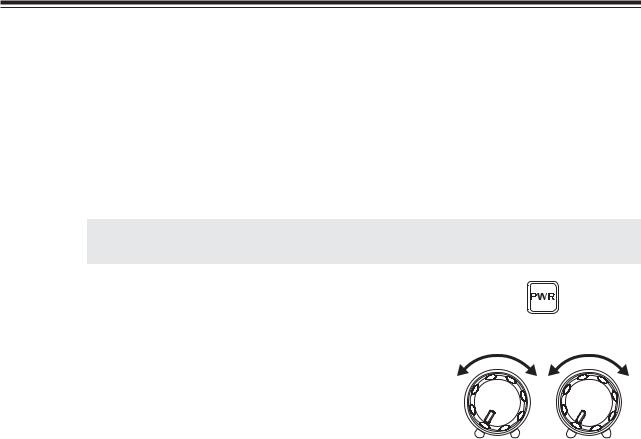
1. |
By pressing the [PWR] key the power turns |
|
on. By pressing the [PWR] key again, the |
|
power turns off. |
2. Audio Volume level setting.
•Turn the VOL knob clockwise to increase the audio volume.
•Turn the VOL countclockwise to decrease the audio volume.
VOL |
SQL |
3. Squelch level setting
Adjust threshold level of the squelch. A squelch eliminates the background noise when a signal is not received.
1. |
Turn the SQL knob clockwise until white- |
|
noise (the background noise when a signal is |
not received) just disappears.
• The SQL should be turned fully countclockwise when receiving weak or unstable signals. The RX LED lights green while the squelch is open (unmuted).
25
Chapter 2 Communications
4. Selecting mode (modulation)
Press the [MODE] key to change the mode as below.
USB  LSB
LSB  AM
AM  FM
FM  CWL
CWL  CWU
CWU
Hold down the [MODE] key more than 1 second to flash the displayed mode.
Select a mode by pressing the [Ÿ/ź] keys, or [UP/DOWN] keys on the microphone.
 USB
USB 
 LSB
LSB 
 AM
AM 
 FM
FM 
 CWL
CWL 
 CWU
CWU 
The flashing display stops at the next key operation.
NOTE: • The SSB mode is most frequently used in HF bands.
Usually, the LSB mode is used below 10 MHz amateur band, and the USB mode is used above 14 MHz amateur band.
•The AM is commonly used to listen to MW and SW broadcasts.
•The FM mode occcupies a wide bandwidth: this will allow reproduction of high quality
sound that is less affected by noise. The FM mode is used in 29 MHz.
•The CW mode is used in Morse communications.
•DX-SR8 remembers the last used mode.
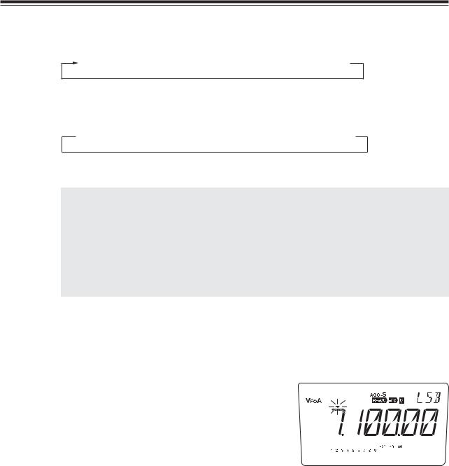
5. Selecting amateur radio bands
Amateur radio bands are frequency bands that hams are allowed to use. DX-SR8 covers all amateur radio bands ranging from 1.8 MHz to 29 MHz.
1. |
Press the [M/KHz] key repeatedly until the |
|
cursor ź flashing appear above the MHz |
frequency indication.
2. |
Press the [Ÿ/ź] keys or push the [UP/ |
|
|
DOWN] key of the microphone to select the |
|
|
desired band. |
|
|
|
|
|
NOTE: |
When you select a band, the LCD will |
|
|
display the last-used frequency in that |
|
|
band. |
|
|
|
|
|
|
|
NOTE: |
When a band is changed, you might |
|
|
hear the clicking noise of relays but |
|
|
this is not a defect. |
|
|
|
26
Chapter 2 Communications
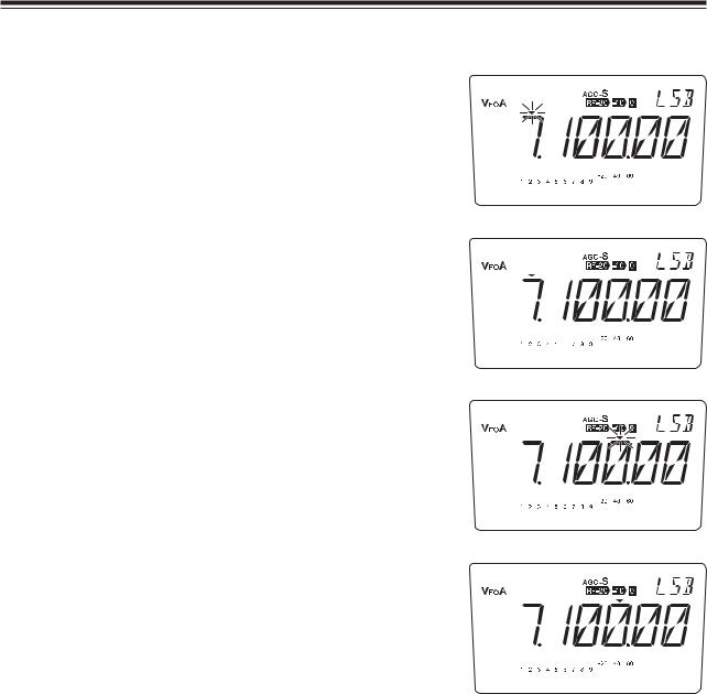
Ɣ Each time the [M/KHz] key is pressed, ź shifts in the following manner:
źflashing above MHz frequency indication.
Changes the BAND.
ź above MHz frequency indication.
Changes the 1 MHz digit.
ź flashing above 1 kHz frequency indication.
Changes the 100 kHz digit.
ź above kHz frequency indication.
Changes by minimum steps.
• Default settings (Default band, frequency and mode for both VFO A and B)
Keypad |
Band (MHz) |
default (Mode) |
Keypad |
Band (MHz) |
default (Mode) |
1 |
1.8 |
1.900.00 MHz (LSB) |
6 |
14 |
14.100.0 MHz (USB) |
2 |
3.5 |
3.600.00 MHz (LSB) |
7 |
18 |
18.100.0 MHz (USB) |
3 |
5.3 |
5.330.50 MHz (USB) |
8 |
21 |
21.100.0 MHz (USB) |
4 |
7 |
7.100.00 MHz (LSB) |
9 |
24 |
24.900.0 MHz (USB) |
5 |
10 |
10.100.0 MHz (USB) |
0 |
28 |
28.100.0 MHz (USB) |
27

Chapter 2 Communications
6. Tuning to a desired frequency
Using VFO's
Press the [FUNC] key, then press the [1] key will switch between the VFO A and VFO B. Select either VFO.
NOTE: DX-SR8 has the VFO and MEMORY modes (see page 51). In the VFO mode, different frequencies and settings can be set in each individual VFO A and VFO B.
Using the main tuning dial
•Turn the main tuning dial clockwise to increase the frequency.
•Turn the main tuning dial counterclockwise to decrease the frequcency.
NOTE: In the SSB and CW modes, rotating the dial will change the frequency in 10 Hz steps (One full rotation will change frequency by 500 Hz). In the AM and FM modes, rotating the dial will change the frequency in 100 Hz steps (One full rotation will change frequency by 5 kHz).
Using the [Ÿ/ź] key ( or using the [UP/DOWN] keys on the microphone)
1. |
Move the cursor to desired position by pressing the [M/KHz] key. |
2. |
Press the [Ÿ] key to increase the frequency. |
|
Press the [ź] key to decrease the frequency. |
NOTE: • Frequency step is different by mode. The step can be selected in the set mode
(see page71,72). The default is 0.1 kHz for SSB and CW, 1 kHz for AM, and 2.5 kHz for FM.
• In mobile operation, the selected frequency may be accidentally changed by
the vibration, etc. To prevent this, use [ |
] key for lock features. (see page |
68) |
|
In "dial-lock" status, tuning is still possible with the [Ÿ/ź] key and RIT control knob.
28
 Loading...