


Abit IS7-M, IS7-V2, IS7-E2, IS7-E, IS7-G Manual
...IS7 Series
(IS7-G, IS7, IS7-E, IS7-E2, IS7-M, IS7-V2)
Intel Pentium 4 System Board
Socket 478
User’s Manual
4200-0375-09 Rev. 1.05

Copyright and Warranty Notice
The information in this document is subject to change without notice and does not represent a commitment on part of the vendor, who assumes no liability or responsibility for any errors that may appear in this manual.
No warranty or representation, either expressed or implied, is made with respect to the quality, accuracy or fitness for any particular part of this document. In no event shall the manufacturer be liable for direct, indirect, special, incidental or consequential damages arising from any defect or error in this manual or product.
Product names appearing in this manual are for identification purpose only and trademarks and product names or brand names appearing in this document are the property of their respective owners.
This document contains materials protected under International Copyright Laws. All rights reserved. No part of this manual may be reproduced, transmitted or transcribed without the expressed written permission of the manufacturer and authors of this manual.
If you do not properly set the motherboard settings, causing the motherboard to malfunction or fail, we cannot guarantee any responsibility.
IS7 Series

Table Of Contents
............................................................................................ |
2 |
|||
........................................................................ |
4 |
|||
Schneller Installation Führer .................................................................. |
6 |
|||
Guide Rapide d'Installation .................................................................... |
8 |
|||
Быстро Направляющий выступ Установки ................................... |
10 |
|||
Guida Rapida Dell'Installazione ........................................................... |
12 |
|||
Chapter 1. |
Introduction .......................................................................... |
1-1 |
||
1-1. |
Features & Specifications ........................................................................ |
1-1 |
||
1-2. |
Layout Diagram (IS7-G/IS7/IS7-E)......................................................... |
1-4 |
||
1-3. |
Layout Diagram (IS7-E2) ........................................................................ |
1-5 |
||
1-4. |
Layout Diagram (IS7-M) ......................................................................... |
1-6 |
||
1-5. |
Layout Diagram (IS7-V2)........................................................................ |
1-7 |
||
Chapter 2. |
Hardware Setup.................................................................... |
2-1 |
||
2-1. |
Install The Motherboard........................................................................... |
2-1 |
||
2-2. Install Pentium® 4 CPU and Heatsink Supporting-Base.......................... |
2-2 |
|||
2-3. |
Install System Memory ............................................................................ |
2-3 |
||
2-4. Connectors, Headers and Switches .......................................................... |
2-6 |
|||
|
(1). |
|
ATX Power Input Connectors........................................................ |
2-6 |
|
(2). |
|
FAN Power Connectors ................................................................. |
2-7 |
|
(3). |
|
CMOS Memory Clearing Header .................................................. |
2-8 |
|
(4). |
|
Wake-up Header............................................................................. |
2-9 |
|
(5). |
|
Front Panel Audio Connection Header ........................................ |
2-10 |
|
(6). |
|
Front Panel Switches & Indicators Headers ................................ |
2-12 |
|
(7). |
|
Infrared Device Header................................................................ |
2-14 |
|
(8). |
|
Additional IEEE1394 Port Headers ............................................. |
2-15 |
|
(9). |
|
Additional USB Port Headers...................................................... |
2-16 |
|
(10). |
System Management Bus Headers............................................... |
2-17 |
|
|
(11). |
Internal Audio Connectors ........................................................... |
2-18 |
|
|
(12). |
Accelerated Graphics Port Slot.................................................... |
2-20 |
|
|
(13). |
Floppy Disk Drive Connector...................................................... |
2-21 |
|
|
(14). |
IDE Connectors............................................................................ |
2-22 |
|
|
(15). |
Serial ATA Connectors ................................................................. |
2-23 |
|
|
(16). |
Status Indicator ............................................................................ |
2-25 |
|
|
(17). |
Back Panel Connectors ................................................................ |
2-27 |
|
User’s Manual

Chapter 3. |
BIOS Setup............................................................................ |
3-1 |
|
3-1. |
SoftMenu Setup........................................................................................ |
3-2 |
|
3-2. |
Standard CMOS Features......................................................................... |
3-4 |
|
3-3. |
Advanced BIOS Features......................................................................... |
3-7 |
|
3-4. |
Advanced Chipset Features.................................................................... |
3-10 |
|
3-5. |
Integrated Peripherals ............................................................................ |
3-12 |
|
3-6. |
Power Management Setup ..................................................................... |
3-19 |
|
3-7. |
PnP/PCI Configurations......................................................................... |
3-22 |
|
3-8. |
PC Health Status .................................................................................... |
3-24 |
|
3-9. |
Load Fail-Safe Defaults ......................................................................... |
3-25 |
|
3-10. |
Load Optimized Defaults ....................................................................... |
3-25 |
|
3-11. |
Set Password .......................................................................................... |
3-25 |
|
3-12. |
Save & Exit Setup .................................................................................. |
3-25 |
|
3-13. |
Exit Without Saving............................................................................... |
3-25 |
|
Appendix A. |
Install Intel Chipset Software Utility............................................... |
A-1 |
|
Appendix B. |
Install Intel Application Accelerator RAID (IS7-G, IS7) .............. |
B-1 |
|
Appendix C. |
Install Audio Driver ......................................................................... |
C-1 |
|
Appendix D. |
Install LAN Driver ........................................................................... |
D-1 |
|
Appendix E. |
Install Silicon Serial ATA RAID Driver (IS7-G) ........................... |
E-1 |
|
Appendix F. |
Install VGA Driver (IS7-M) ............................................................ |
F-1 |
|
Appendix G. |
Install USB 2.0 Driver ..................................................................... |
G-1 |
|
Appendix H. |
ABIT EQ (The Hardware Doctor Utility) ....................................... |
H-1 |
|
Appendix I. |
FlashMenu (BIOS Update Utility) ................................................... |
I-1 |
|
Appendix J. |
Troubleshooting (Need Assistance?)................................................ |
J-1 |
|
Appendix K. |
How to Get Technical Support ........................................................ |
K-1 |
|
IS7 Series

1
User’s Manual
2 |
|
|
|
|
|
已包覆在隨本主機板所附的驅動程式與應用光碟之中。
(Zero Insertion Force, ZIF) Socket 478 Intel® Pentium® 4 CPUCPU Pentium® 4 Socket 478
1.Socket 478
Pentium® 4
2.90
3. 到散熱片完全地蓋住處理器為止。
5. 孔扣上。
IS7 Series
|
3 |
|
|
|
|
您可以使用塑膠墊片來讓螺絲與主機板的PCB
1.DIMM
2.DIMM
3.DIMM
4.DIMMDIMM
DIMMDIMM
5.DIMM DIMM DIMM
SCSI AGP
ATX12V
ATX ATX12V
BIOS
BIOS
User’s Manual
4 |
|
|
|
|
|
ーズマニュアルはこのマザーボードに付属するドライバとユーティリティCD
CPU
ZIF () Socket 478 Intel® Pentium® 4 CPU CPU Pentium® 4 Socket 478
1.478 ZIF
Pentium® 4 PCB
2.CPU90 CPUCPUCPU CPU
3.CPU
のリテンションロックが、4
IS7 Series
|
5 |
|
|
|
|
RAM
1.DIMM
2.DIMM 2
DIMM DIMM
5.DIMM 2
ります。これらの手順を開始する前に、アースされた金属物体に軽く触れて静電気を必ず放電し てください。
プラグは、通常マザーボードにあるコネクタに1 1 SCSI AGP
ATX12V
ATX12V
BIOS
BIOS Setup
User’s Manual

6 |
Schneller Installation Führer |
|
|
Schneller Installation Führer
Beziehen Sie sich bitte für detaillierte Informationen über diese Hauptplatine auf die vollständige Version des Benutzerbuchs. Diese Schnellinstallationsanleitung ist für erfahrene Systemaufbauer gedacht. Ist es Ihr erster Versuch ein Computersystem aufzubauen, dann empfehlen wir Ihnen zuerst das vollständige Benutzerhandbuch zu lesen oder einen Techniker zum Aufbauen des Systems zu Hilfe zu holen. (Ein komplettes Handbuch finden Sie auf der CD mit den Treibern und Hilfsprogrammen, die diesem Motherboard beiliegt.)
Installation von CPU-Kühlblech & Lüftereinheit
Dieses Motherboard verfügt über einen ZIF (Zero Insertion Force) Sockel 478 zur Installation eines Intel® Pentium® 4 CPU. Ihre CPU sollte über ein Kühlblech und einen Lüfter verfügen. Wenn dies nicht der Fall ist, kaufen Sie bitte diese Teile speziell für den Pentium® 4 Sockel 478.
1.Finden Sie den 478-polige ZIF-Sockel auf dem Motherboard. Befestigen Sie die Basis des Haltemoduls auf dem Motherboard.
Achtung: Wenn Sie ein speziell für den Pentium® 4 konstruiertes Gehäuse verwenden, achten Sie bitte auf die Lage der Metallbolzen bzw. Abstandhalter, wenn sie schon im Gehäuse installiert sind. Achten Sie darauf, dass kein Kontakt zwischen Metallbolzen bzw. Abstandhalter und den gedruckten Schaltkreisen bzw. leitfähigen Teilen auf dem PCB entsteht.
2.Ziehen Sie den Hebel des Prozessorsockels seitwärts vom Sockel und dann im 90 Grad-Winkel nach oben. Setzen Sie den Prozessor mit der korrekten Ausrichtung hinein. Wenden Sie keine Gewalt beim Einsetzen des Prozessors ein; er passt nur in eine Ausrichtung hinein. Drücken Sie den Sockelhebel wieder herunter, während Sie den Prozessor heruntergedrückt halten.
3.Setzen Sie das Kühlblech mit der Oberseite nach unten auf den Prozessor, bis es den Prozessor völlig abdeckt.
4.Setzen Sie die Kühlblechabdeckung und die Haltemechanismus-Einheit auf das Kühlblech. Vergewissern Sie sich, dass alle vier Halteklammern zu jeder Seite der Abdeckung in die Haltelöcher greifen.
5.Drücken Sie den Halteclip auf beiden Seiten von
Lüfter und Haltemechanismuseinheit nieder, bis er in die Basis des Haltemoduls einschnappt.
6.Lüfter und Haltemechanismus-Einheit und die Basis des Haltemoduls sollten nun fest miteinander verriegelt sein und das Kühlblech sich in ihrem Innern befinden..
IS7 Series
Schneller Installation Führer |
7 |
|
|
Achtung: Vergessen Sie nicht, die korrekte Busfrequenz und -Multiplikator für Ihren Prozessor einzustellen.
Installieren der Hauptplatine im Gehäuse
Nach der Installation des Prozessors können Sie anfangen die Hauptplatine im Computergehäuse zu befestigen. Die meisten Gehäuse haben eine Bodenplatte, auf der sich eine Reihe von Befestigungslöcher befinden, mit deren Hilfe Sie die Hauptplatine sicher verankern können und zugleich Kurzschlüsse verhindern. Verwenden Sie entweder die Dübeln oder die Abstandhalter, um die Hauptplatine auf der Bodenplatte des Gehäuses zu befestigen.
Installation der RAM-Module
1.Finden Sie den DIMM-Steckplatz auf dem Board.
2.Halten Sie ie beiden Ränder des DIMM-Moduls vorsichtig fest, wobei Sie darauf achten, nicht die Anschlüsse zu berühren.
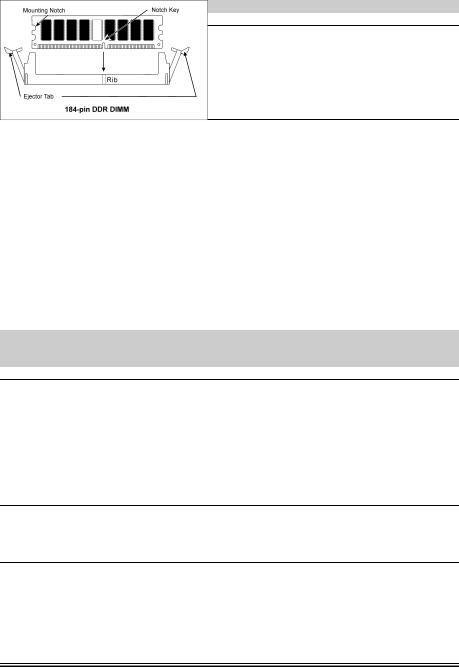
3.Richten Sie die Nut am Modul mit der Erhöhung am Steckplatz aus.
4.Drücken Sie das Modul fest in die Steckplätze, bis die Auswurflaschen zu beiden Seiten des Steckplatzes automatisch in die
Befestigungskerbe einschnappen. Wenden Sie keine Gewalt beim Einsetzen des DIMM-Moduls an; es paßt nur in eine Richtung hinein.
5.Zum Ausbau der Module drücken Sie die beiden Auswurflaschen auf dem Steckplatz nach außen zusammen und ziehen das Modul heraus.
Anschlüsse, Sockel, Schalter und Adapter
Im Inneren des Gehäuses findet man in jedem Computer viele Kabel und Stecker, die angeschlossen werden müssen. Diese Kabel und Stecker werden normalerweise einzeln mit den Anschlüssen auf der Hauptplatine verbunden. Sie müssen genau auf die Anschlussorientierung der Kabel achten und, wenn vorhanden, sich die Position des ersten Pols des Anschlusses merken. Wenn Sie Adapter wie z.B. SCSI-Adapter, AGP-Adapter usw. installieren, befestigen Sie bitte die Adapter immer mit Hilfe der Schrauben auf die Rückseite des Computergehäuses.
Für detaillierte Informationen beziehen Sie sich bitte auf das vollständige Benutzerhandbuch.
Verbinden der Netzstecker mit dem ATX12V-Anschluss
Denken Sie daran, den Anschluss des ATX-Netzteils fest in das Ende mit dem ATX12V-Anschluss zu drücken, um eine feste Verbindung zu garantieren.
BIOS-Setup
Schalten Sie nach der vervollständigten Hardwareinstallation den Computer ein und gehen zur Option im BIOS, um die Prozessorparameter einzustellen. Für detaillierte Informationen beziehen Sie sich bitte auf das vollständige Benutzerhandbuch.
User’s Manual
8 |
Guide Rapide d'Installation |
|
|
Guide Rapide d'Installation
Pour des informations relatives à cette carte mère plus détaillées, veuillez vous référer à notre version complète du manuel utilisateur. Ce guide d’installation rapide est créé pour les assembleurs système expérimentés. S’il s’agit de votre premier essai pour installer un ordinateur, nous vous suggérons de lire d’abord le manuel en version complète ou de demander l’aide d’un technicien pour vous aider à configurer le système ordinateur. (Un manuel de l'utilisateur complet est disponible en naviguant dans le CD des pilotes et utilitaires fournis avec la carte mère.)
Installer le Dissipateur de Chaleur du CPU et l’Assemblage du Ventilateur
Cette carte mère fournit un support ZIF (Zero Insertion Force) Socket 478 permettant d'installer le Microprocesseur Intel® Pentium® 4. Le microprocesseur que vous achetez doit être muni d'un système de refroidissement avec dissipateur thermique et ventilateur. Dans le cas contraire, veuillez en acheter un, conçu spécialement pour les microprocesseurs Pentium® 4 Socket 478.
1.Localisez le socle ZIF 478-broches sur la carte-mère. Serrez la Base du Module de Rétention sur la carte.
Attention: Si vous utilisez un châssis spécialement conçu pour Pentium® 4, veuillez faire attention à l’emplacement des Clous en Métal ou des Espaceurs installés sur le châssis. Ne laissez jamais les Clous en Métal ou les Espaceurs entrer en contact des circuits imprimés ou des composants sur le PCB.
2.Tirez le levier du socle CPU sur les côtés jusque sur un angle d’environs 90. Insérez le CPU avec l’orientation correcte. N’utilisez pas trop de force pour insérer le CPU; il n’ira que selon une seule orientation. Refermez ensuite le levier du socle tout en maintenant le CPU.
3.Placez le dissipateur de chaleur face vers le bas dans le CPU jusqu’à ce qu’il recouvre celui-ci complètement.
4.Placez le Ventilateur et l’Assemblage du Mécanisme de Retient dans le dissipateur de chaleur. Assurez-vous que les quatre Verrous de Retient sur chaque côté du Ventilateur et du Mécanisme de Retient dans les Trous de Retient.
5.Pressez le Verrou de Retient sur les deux côtés du Ventilateur et du Mécanisme de Retient pour verrouiller ensemble avec la Base du Module de Retient.
6.Le Ventilateur, le Mécanisme de Retient et la Base du Module de Retient doivent maintenant être verrouillés l’un sur l’autre avec le dissipateur de chaleur à l’intérieur.
IS7 Series
Guide Rapide d'Installation |
9 |
|
|
Attention: N’oubliez pas de programmer la fréquence de bus correcte et le multiple pour votre processeur.
Installer la Carte Mre dans le Châssis
Une fois que vous aurez installé le processeur sur la carte mère, vous pourrez commencer à fixer la carte mère sur le châssis. Tout d’abord, vous avez besoin de fixer la carte mère sur le châssis. La plupart des châssis d’ordinateur possèdent une base sur laquelle il y a nombreux trous de montage permettant à la carte mère d’être fixée fermement, et en même temps d’éviter les court-circuits. Utilisez les talons ou les entretoises fixés sur le châssis pour fixer la carte mère.
Installer des Modules RAM
1.Localisez le socle DIMM sur la carte.
2.Maintenez les deux bords du module DIMM avec précaution, en évitant de toucher ses connecteurs.
3.Alignez la touche du cran avec la ligne sur le socle.
4.Pressez fermement le module dans les socles jusqu’à ce que les languettes d’éjection sur les deux côtés du socle aillent automatiquement dans le cran de montage. Ne forcez pas à l’excès sur le module DIMM car celui-ci ne peut aller que selon une seule orientation.
5.Pour enlever des modules DIMM, pressez simultanément les deux languettes d’éjection sur le socle, puis sortez le module DIMM.
Attention: L’électricité statique risque d’endommager les composants électroniques de l’ordinateur ou des cartes optionnelles. Avant de commencer ces procédures, assurez-vous de bien décharger toute l’électricité statique en touchant rapidement un objet métallique relié au sol.
Connecteurs, Socles de connexion, Interrupteurs et Adaptateurs
A l’intérieur du boîtier de n’importe quel ordinateur il y a plusieurs câbles et prises qui doivent être connectés. Ces câbles et prises sont habituellement connectés les uns après les autres aux connecteurs situés sur la carte mère. Vous avez besoin de faire attention au sens de connexion des câbles et, s’il y a lieu, remarquez la position de la première broche du connecteur. Vous installerez certains adaptateurs pour des besoins spéciaux, tels adaptateurs SCSI, adaptateurs AGP, etc. Lorsque vous les installez dans les emplacements situés sur la carte mère, veuillez les fixer sur le panneau arrière du châssis à l'aide des vis.
Pour les informations détaillées, veuillez vous référer au manuel utilisateur en version complète.
Brancher les connecteurs d'alimentation dans les connecteurs ATX12V
Souvenez-vous que vous devez pousser le connecteur de votre alimentation fermement dans le connecteur ATX12V pour assurer une bonne connexion.
Configuration du BIOS
Une fois le matériel installé complètement, démarrez l'ordinateur et allez sur l'item dans le BIOS pour configurer les paramètres du processeur. Pour les informations détaillées, veuillez vous référer à la version complète du manuel utilisateur.
User’s Manual
10 |
Быстро Направляющий выступ Установки |
|
|
Быстро Направляющий выступ Установки
Более подробные сведения о материнской плате приведены в руководстве пользователя. Краткое руководство по установке предназначено для опытных специалистов. Если вы собираете компьютер впервые, ознакомьтесь сперва с руководством пользователя или попросите техника помочь в настройке компьютерной системы.
Установка радиатора и вентилятора охлаждения процессора
На этой системной плате используется гнездо ZIP (с нулевым усилием установки) типа 'Socket 478' для процессора Intel® Pentium® 4. В комплект приобретаемого процессора должны входить радиатор и вентилятор. В противном случае следует приобрести радиатор и вентилятор, предназначенные для процессора Pentium® 4 с разъемом 'Socket 478'.
1.Найдите на системной плате 478-выводной разъем типа ZIF. Закрепите основание радиатора на системной плате.
Внимание: Устанавливая плату в корпус, разработанный специально для Pentium® 4, обратите внимание на уже установленный крепеж (металлические стойки, зажимы). Убедитесь, что установленный крепеж не касается системной платы или ее выводов.
2.Оттяните рычаг фиксации процессора в сторону и поднимите его на 90 градусов вверх. Расположив процессор соответствующим образом, вставьте его в разъем. Не прилагайте излишних усилий, чтобы вставить процессор. Процессор легко устанавливается, если вы правильно совместили его с разъемом. Установив процессор, опустите рычаг фиксации процессора на место.
3.Положите на процессор радиатор так, чтобы он полностью накрывал процессор.
4.Положите на радиатор вентилятор и фиксирующий механизм. Убедитесь, что все четыре фиксатора вентилятора и фиксирующего механизма вошли в предназначенные отверстия и защелкнулись.
5.Зафиксируйте вентилятор на основании радиатора, опустив рычажки, расположенные с обеих сторон фиксирующего механизма.
6.Вентилятор, фиксирующий механизм и основание радиатора должны быть надежно закреплены вместе с вентилятором.
IS7 Series

Быстро Направляющий выступ Установки |
11 |
|
|
Внимание: Установите соответствующие частоту и кратность шины процессора.
Установка материнской платы в корпус
После установки процессора на материнскую плату можно начинать установку материнской платы в корпус. Большая часть корпусов оборудована основанием, в котором проделаны монтажные отверстия, которые позволяют надежно закрепить материнскую плату и предотвратить короткие замыкания. Для крепления материнской платы к основанию используются винты и прокладки.
Установка модулей памяти
1.Найдите на системной плате разъем для модулей памяти DIMM.
2.Аккуратно, за два конца, возьмите модуль памяти, не касаясь контактов.
3.Совместите выемку в модуле памяти с выступом в разъеме.
4.Нажмите на модуль так, чтобы лепестки выталкивателя с обеих сторон разъема
автоматически защелкнулись и вошли в пазы. Не применяйте при установке излишнюю силу. Модуль входит в разъем только в одном положении.
5.Для извлечения модулей памяти DIMM одновременно нажмите на лепестки выталкивателя и вытащите модуль.
Внимание: Статическое электричество может стать причиной выхода из строя электронных компонентов компьютера. Перед началом данной процедуры снимите с себя статический заряд, коснувшись заземленного металлического предмета.
Разъемы, переключатели и адаптеры
Внутри корпуса компьютера необходимо расположены несколько кабелей и вилок, которые необходимо подключить. Обычно эти кабели подключаются к разъемам, расположенным на материнской плате. При подключении любого кабеля необходимо обращать внимание на расположение первого контакта разъема. Для особых целей могут потребоваться специальные адаптеры, например, адаптер SCSI, адаптер AGP и т.п.. При установке адаптеров в гнезда материнской платы закрепите их на задней панели с помощью винтов.
За более подробной информацией обращайтесь к полному руководству пользователя.
Подключение кабелей питания к разъемам ATX12V
Обратите внимание, разъем блока питания ATX необходимо вставить в разъем ATX12V до упора, чтобы обеспечить надежное соединение.
Настройка BIOS
По окончании установки аппаратуры включите питание и перейдите в меню BIOS Setup, чтобы настроить параметры процессора. За более подробной информацией обращайтесь к руководству пользователя.
User’s Manual
12 |
Guida Rapida Dell'Installazione |
|
|
Guida Rapida Dell'Installazione
Per maggiori e dettagliate informazioni su questa scheda madre si prega di fare riferimento alla versione integrale del Manuale utente. Questa guida all’installazione veloce è intesa per costruttori esperi di sistemi. Se questa è la prima volta che si cerca di installare un sistema, si consiglia di leggere, innanzi tutto, la versione integrale del manuale oppure di chiedere aiuto ad un tecnico per l’installazione.
Installare il dispersore di calore CPU ed il gruppo della ventolina
Questa scheda madre fornisce una presa “Socket 478” ZIF (Zero Insertion Force – forza d’inserimento zero) per installare il processore Intel® Pentium® 4. Il processore acquistato dovrebbe essere fornito di dispersore di calore e ventolina per il raffreddamento. In caso contrario acquistare un dispersore di calore specifico per la presa Socket 478 Pentium®.
1.Ubicare la presa ZIF a 478 pin sulla scheda madre. Stringere la base del modulo di trattenimento sulla scheda madre.
Attenzione: Se si impiega un telaio progettato specificatamente per il processore Pentium® 4, si prega prestare attenzione all’ubicazione delle guarnizioni metalliche o degli spaziatori, nel caso in cui siano già installati sul telaio. Assicurarsi di non permettere alle guarnizioni metalliche od agli spaziatori di entrare in contatto con il cavo o con le parti del circuito sul PCB.
2.Tirare di lato la leva della presa CPU, allontanandola dalla presa; poi sollevarla di 90 gradi. Inserire la CPU con l’orientamento corretto. Non sforzare per inserire la CPU poiché si adatta solamente in un dato orientamento. Chiudere la leva della presa trattenendo la CPU.
3.Mettere il dispersore di calore a faccia in giù sulla CPU finché la copre completamente.
4.Mettere la ventolina ed il gruppo del meccanismo di trattenimento sul dispersore di calore. Assicurarsi che tutti i quattro fermi di trattenimento, su ciascun lato della ventolina e del gruppo del meccanismo di trattenimento, scattino in posizione nei fori ti trattenimento.
5.Spingere verso il basso i fermi di trattenimento su
entrambi i lati della ventolina e del gruppo del meccanismo di trattenimento per fissarli con la base del modulo di trattenimento.
6.La ventolina, il gruppo del meccanismo di trattenimento e la base del modulo di trattenimento ora dovrebbero essere fissati gli uni agli altri trattenendo al loro interno il dispersore di calore.
IS7 Series
Guida Rapida Dell'Installazione |
13 |
|
|
Attenzione: Non dimenticare di impostare la corretta frequenza multipla e BUS per il processore.
Installazione della scheda madre sul telaio
Dopo avere installato il processore sulla scheda madre si può iniziare a fissare la scheda madre sul telaio. Innanzi tutto è necessario fissare la scheda madre al telaio. La maggior parte dei telai ha una base sulla quale sono presenti diversi fori di montaggio che permettono di fissare in modo accurato la scheda madre e, allo stesso tempo, di prevenire corto circuiti. Impiegare le borchie o gli spaziatori attaccati al telaio per fissare la scheda madre.
Installare i moduli RAM
1.Ubicare gli alloggiamenti DIMM sulla scheda.
2.Tenere con delicatezza i lati del modulo DIMM senza toccare i connettori.
3.Allineare la tacca sul modulo con la nervatura dell’alloggiamento.
4.Premere con fermezza il modulo nell’alloggiamento finché le linguette d’espulsione su entrambi i lati dell’alloggiamento
scattano sulla tacca di montaggio. Non forzare eccessivamente il modulo DIMM perché quest’ultimo si adatta solamente in una direzione.
5.Per rimuovere i moduli DIMM spingere contemporaneamente le due linguette d’espulsione sull’alloggiamento, poi estrarre il modulo DIMM.
Attenzione: L’elettricità statica può danneggiare i componenti elettronici del computer o delle schede. Prima di iniziare queste procedure, assicurarsi di avere scaricato completamente l’elettricità statica toccando brevemente un oggetto metallico con massa a terra.
Connettori, collettori, interruttori ed adattatori
All’interno della copertura di ogni computer ci sono diversi cavi e prese che devo essere collegati. Questi cavi e prese sono solitamente collegati uno ad uno ai connettori situati sulla scheda madre. E’ necessario prestare particolare attenzione a qualunque orientamento del collegamento che possono avere i cavi e, se necessario, notare la posizione del primo pin del connettore. Si installeranno alcuni adattatori per particolari necessità quali l’adattatore SCSI, AGP, eccetera. Quando si installano gli adattatori sugli slot della scheda madre, si ricorda di fissarli con le viti anche sul pannello posteriore del telaio.
Per informazioni dettagliate si prega di fare riferimento alla versione integrale del Manuale utente.
Collegamento dei connettori d’alimentazione ai connettori ATX12V
Ricordarsi che è necessario spingere con fermezza fino in fondo il connettore della sorgente d’alimentazione ATX al connettore ATX12V, assicurando così un buon collegamento.
Impostazione BIOS
Quando l’hardware è stato installato completamente, accendere il computer ed andare alla voce BIOS per impostare i parametri del processore. Per informazioni dettagliate si prega di fare riferimento alla versione integrale del Manuale utente.
User’s Manual

14
IS7 Series

Introduction |
1-1 |
|
|
Chapter 1. Introduction
1-1. Features & Specifications
1.CPU
•Supports Intel Pentium 4 Socket 478 processor with 800MHz, 533MHz, and 400MHz (for Northwood only) System Data Bus
•Supports Intel Hyper-Threading Technology
2.Chipset
•Intel 82865PE (MCH) + 82801ER (ICH5R) (IS7-G/IS7)
•Intel 82865PE (MCH) + 82801EB (ICH5) (IS7-E/IS7-E2)
•Intel 82865G (MCH) + 82801EB (ICH5) (IS7-M)
•Intel 82848P (MCH) + 82801EB (ICH5) (IS7-V2)
•Supports Hi-Speed Universal Serial Bus (USB 2.0)
•Supports Ultra ATA/100/66/33 mode
•Integrated Intel “Extreme Graphics 2” graphics controller (IS7-M)
3.Memory
•Supports 4 DIMM single/dual channel DDR 400/333/266 (Max. 4GB)
(IS7-G/IS7/IS7-E/IS7-M)
•Supports 2 DIMM single/dual channel DDR 400/333/266 (Max. 2GB) (IS7-E2)
•Supports 2 DIMM single channel DDR 400/333/266 (Max. 2GB) (IS7-V2)
4.AGP
•Accelerated Graphics Port connector supports AGP 8X/4X Interface (0.8V/1.5V)
5.LAN
•Onboard 10/100/1000M LAN Controller (IS7-G)
•Onboard 10/100M LAN Controller (IS7/IS7-E/IS7-M/IS7-E2/IS7-V2)
6.Serial ATA RAID
•Onboard 2 channels of Serial ATA 150MB/s data transfer rate with RAID function (RAID 0/RAID 1) via ICH5R South Bridge (IS7-G/IS7)
•Onboard 2 channels of Serial ATA 150MB/s data transfer rate with RAID function (RAID 0/RAID 1) via Silicon Image PCI Chip (IS7-G)
•Onboard 2 channels of Serial ATA 150MB/s data transfer rate via ICH5 South Bridge
(IS7-E/IS7-M/IS7-E2/IS7-V2)
7.USB 2.0
•8x USB 2.0 ports support 480 Mb/s data transfer rate
8.IEEE 1394
•Supports IEEE 1394a at 400/200/100 Mb/s data transfer rate (IS7-G/IS7)
User’s Manual

1-2 |
Chapter 1 |
|
|
9.Audio
•Onboard 6-Channel AC 97 CODEC
•Professional digital audio interface supports S/PDIF In/Out (IS7-G/IS7/IS7-E)
10.ABIT Engineered
•ABIT SoftMenu™ Technology
•ABIT EQ™
•ABIT FANEQ™ (IS7-G/IS7/IS7-E/IS7-M/IS7-E2)
•ABIT FlashMenu™
11.Internal I/O Connectors
•1x AGP slot
•5x PCI slots
•1x Floppy port supports up to 2.88MB
•2x Ultra ATA/100/66/33 connectors
•4x Serial ATA 150 connectors (IS7-G)
•2x Serial ATA 150 connectors (IS7/IS7-E/IS7-M/IS7-E2/IS7-V2)
•2x USB 2.0 headers
•2x IEEE 1394a headers (IS7-G/IS7)
•1x CD-IN header
•1x AUX-IN header (IS7-G/IS7/IS7-E/IS7-M)
•1x IrDA header (IS7-G/IS7/IS7-E/IS7-M)
12.Back Panel I/O
•1x PS/2 Keyboard, 1x PS/2 mouse
•1x Serial port connectors, 1x Parallel port connector
•1x S/PDIF In connector (IS7-G/IS7/IS7-E)
•1x S/PDIF Out connector (IS7-G/IS7/IS7-E)
•1x VGA Out connector (IS7-M)
•1x AUDIO1 connector
•1x AUDIO2 connector (IS7-G/IS7/IS7-E/IS7-M)
•2x USB 2.0, 1x IEEE 1394 Connector (IS7-G/IS7)
•2x USB 2.0 Connectors (IS7-E/IS7-M/IS7-E2/IS7-V2)
•2x USB 2.0, 1x RJ-45 LAN Connector
13.Miscellaneous
•ATX form factor
•Hardware Monitoring – including Fan Speed, Voltages, CPU and system temperature
•Supports Wake Up by LAN, Modem Ring, RTC Alarm, Keyboard and Mouse Power On
•Supports STR (Suspend to RAM)
IS7 Series
Introduction |
1-3 |
|
|
14. Order Information
Model |
Chipset |
LAN |
SB SATA |
PCI SATA |
IEEE 1394 |
|
|
|
|
|
|
IS7-G |
865PE + ICH5R |
10/100/1000M |
RAID 0/1 |
RAID 0/1 |
3 Ports |
IS7 |
865PE + ICH5R |
10/100M |
RAID 0/1 |
- |
3 Ports |
IS7-E |
865PE + ICH5 |
10/100M |
2 Ports |
- |
- |
|
|
|
|
|
|
IS7-E2 |
865PE + ICH5 |
10/100M |
2 Ports |
- |
- |
IS7-M |
865G + ICH5 |
10/100M |
2 Ports |
- |
- |
IS7-V2 |
848P + ICH5 |
10/100M |
2 Ports |
- |
- |
The Switching Power Supply must meet ATX 2.03 specification with ATX12V and AUX Power connectors.
Supports Wake On LAN, Modem, but your ATX power supply 5V standby power must be able to provide at least a 720mA current capacity. Otherwise, the functions may not work normally.
Specifications and information contained herein are subject to change without notice.
User’s Manual

1-4 |
Chapter 1 |
|
|
1-2. Layout Diagram (IS7-G/IS7/IS7-E)
IS7 Series
Introduction |
1-5 |
|
|
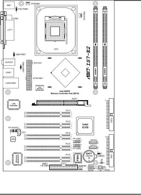
1-3. Layout Diagram (IS7-E2)
User’s Manual
1-6 |
Chapter 1 |
|
|
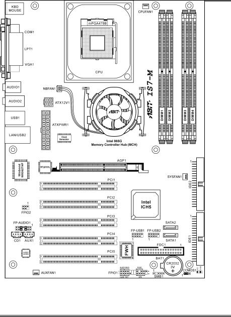
1-4. Layout Diagram (IS7-M)
IS7 Series
Introduction |
1-7 |
|
|
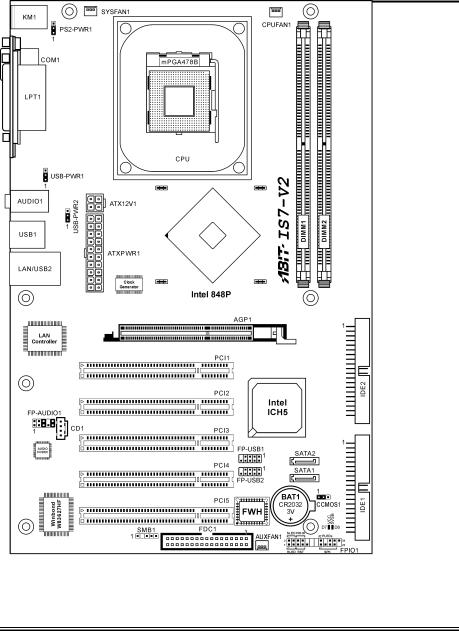
1-5. Layout Diagram (IS7-V2)
User’s Manual

1-8 |
Chapter 1 |
|
|
IS7 Series
Hardware Setup |
2-1 |
|
|
Chapter 2. Hardware Setup
Before the Installation: Turn off the power supply switch (fully turn off the +5V standby power), or disconnect the power cord before installing or unplugging any connectors or add-on cards. Failing to do so may cause the motherboard components or add-on cards to malfunction or damaged.
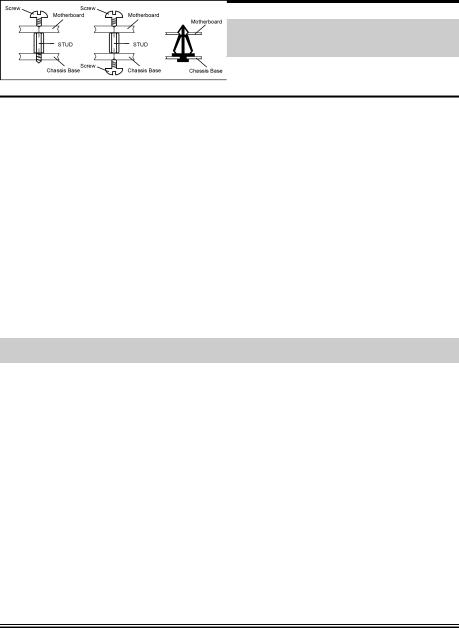
2-1. Install The Motherboard
Most computer chassis have a base with many mounting holes to allow motherboard to be securely attached on and at the same time, prevented from short circuits. There are two ways to attach the motherboard to the chassis base:
1.use with studs
2.or use with spacers
In principle, the best way to attach the board is to use with studs. Only if you are unable to do this should you attach the board with spacers. Line up the holes on the board with the mounting holes on the chassis. If the holes line up and there are screw holes, you can attach the board with studs. If the holes line up and there are only slots, you can only attach with spacers. Take the tip of the spacers and insert them into the slots. After doing this to all the slots, you can slide the board into
position aligned with slots. After the board has been positioned, check to make sure everything is OK before putting the chassis back on.
ATTENTION: To prevent shorting the PCB circuit, please REMOVE the metal studs or spacers if they are already fastened on the chassis base and are without mounting-holes on the motherboard to align with.
User’s Manual
2-2 |
Chapter 2 |
|
|
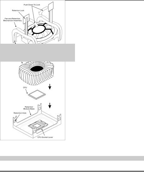
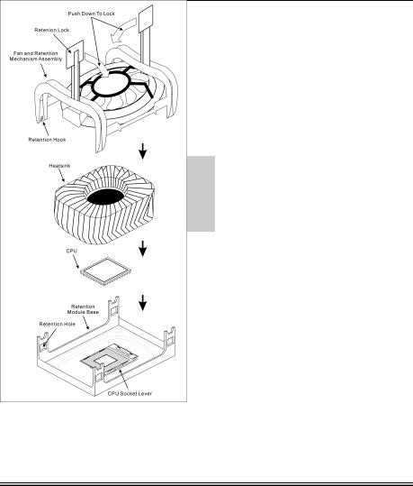
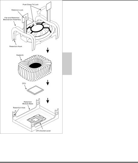
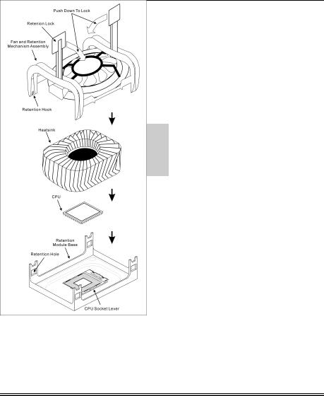
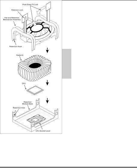
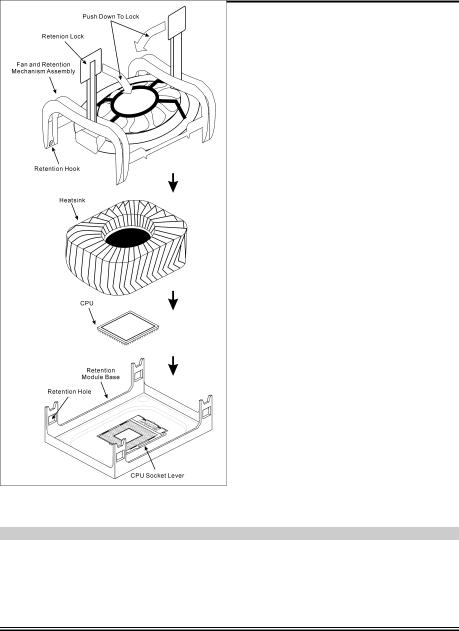
2-2. Install Pentium® 4 CPU and Heatsink Supporting-Base
This motherboard provides a ZIF (Zero Insertion Force) Socket 478 to install Intel® Pentium® 4 CPU. The CPU you bought should have a kit of heatsink and cooling fan along with. If that’s not the case, buy one specially designed for Pentium® 4 Socket 478.
1.Locate the 478-pin ZIF socket on the motherboard. Fasten the Retention Module Base onto the motherboard.
ATTENTION: If you are using chassis specially designed for Pentium® 4, please pay attention to the location of metal studs or spacers if they are already installed on the chassis. Be careful not let the metal studs or spacers contact the printed circuit wire or parts on the PCB.
2.Pull the CPU socket lever sideways away from the socket and then upwards to 90 degree. Insert the CPU with the correct orientation. Do not use extra force to insert CPU; it only fits in one orientation. Close down the socket lever while holding down the CPU.
3.Put the heatsink faces down onto the CPU until it completely covers the CPU.
4.Put the Fan and Retention Mechanism Assembly onto the heatsink. Make sure all the four Retention Locks at each side of the Fan and Retention Mechanism Assembly snap into the Retention Holes.
5.Push down the Retention Lock at both sides of the Fan and Retention Mechanism Assembly to lock up together with the Retention Module Base.
6.The Fan and Retention Mechanism Assembly and Retention Module Base should now
firmly lock up with each other with the heatsink inside.
ATTENTION: Do not forget to set the correct bus frequency and multiple for your processor.
IS7 Series
Hardware Setup |
2-3 |
|
|
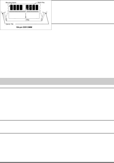
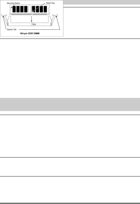
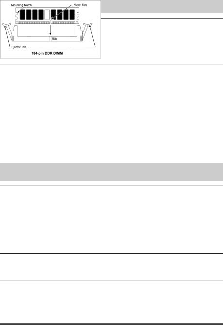
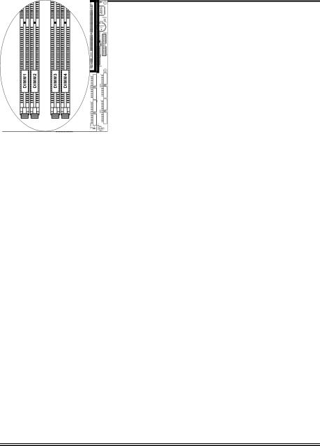
2-3. Install System Memory
IS7-G/IS7/IS7-E/IS7-M:
This motherboard provides four 184-pin DDR DIMM slots for Single/Dual Channel DDR 400/333/266 memory modules with memory expansion size up to 4GB.
To reach the performance of Dual Channel DDR, the following rules must be obeyed:
•When installing TWO DIMM modules: Install DIMM modules of the same type and size for slots [DIMM1]+[DIMM3] or slots [DIMM2]+[DIMM4].
•When installing FOUR DIMM modules: Install DIMM modules of the same type and size for slots [DIMM1]+[DIMM3], and slots [DIMM2]+[DIMM4].
IS7-G/IS7/IS7-E: IS7-M:
Bank |
|
Memory Module |
Total Memory |
|
|
|
|
Bank 0, 1 (DIMM1) |
|
128, 256, 512MB, 1GB |
128MB ~ 1GB |
|
|
|
|
Bank 2, 3 (DIMM2) |
|
128, 256, 512MB, 1GB |
128MB ~ 1GB |
|
|
|
|
Bank 4, 5 (DIMM3) |
|
128, 256, 512MB, 1GB |
128MB ~ 1GB |
|
|
|
|
Bank 6, 7 (DIMM4) |
|
128, 256, 512MB, 1GB |
128MB ~ 1GB |
|
|
|
|
|
Total System Memory |
128MB ~ 4GB |
|
|
|
|
|
User’s Manual
2-4 |
Chapter 2 |
|
|
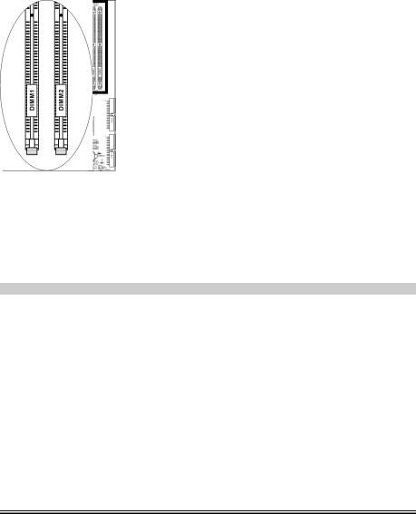
IS7-E2/IS7-V2:
This motherboard provides 2 184-pin DDR DIMM sites for memory expansion available from minimum 128MB to maximum 2GB.
IS7-E2: IS7-V2:
Bank |
|
Memory Module |
Total Memory |
|
|
|
|
Bank 0, 1 (DIMM1) |
|
128, 256, 512MB, 1GB |
128MB ~ 1GB |
|
|
|
|
Bank 2, 3 (DIMM2) |
|
128, 256, 512MB, 1GB |
128MB ~ 1GB |
|
|
|
|
|
Total System Memory |
128MB ~ 2GB |
|
|
|
|
|
NOTE: No hardware or BIOS setup required after adding or removing memory modules.
IS7 Series
 Loading...