


 Loading...
ABIT AN8, AN8 SLI, AN8 ULTRA, AN8 V2.0, AN8-3 EYE User Manual
...AN8 Series
(AN8 SLI/AN8 Ultra/AN8-3rd Eye
/AN8 V2.0/AN8/AN8-V)
AMD Athlon 64/64FX System Board
Socket 939
User’s Manual
4200-0438-11 Rev. 1.04

Copyright and Warranty Notice
The information in this document is subject to change without notice and does not represent a commitment on part of the vendor, who assumes no liability or responsibility for any errors that may appear in this manual.
No warranty or representation, either expressed or implied, is made with respect to the quality, accuracy or fitness for any particular part of this document. In no event shall the manufacturer be liable for direct, indirect, special, incidental or consequential damages arising from any defect or error in this manual or product.
Product names appearing in this manual are for identification purpose only and trademarks and product names or brand names appearing in this document are the property of their respective owners.
This document contains materials protected under International Copyright Laws. All rights reserved. No part of this manual may be reproduced, transmitted or transcribed without the expressed written permission of the manufacturer and authors of this manual.
If you do not properly set the motherboard settings, causing the motherboard to malfunction or fail, we cannot guarantee any responsibility.
AN8 Series

Table of Contents
Chapter 1. Introduction .......................................................................... |
1-1 |
|
1-1. |
Features & Specifications ........................................................................ |
1-1 |
1-2. Layout Diagram (AN8 SLI) ...................................................................... |
1-3 |
|
1-3. Layout Diagram (AN8 Ultra)................................................................... |
1-4 |
|
1-4. |
Layout Diagram (AN8-3rd Eye/AN8)........................................................ |
1-5 |
1-5. |
Layout Diagram (AN8 V2.0) .................................................................... |
1-6 |
1-6. |
Layout Diagram (AN8-V)......................................................................... |
1-7 |
Chapter 2. |
Hardware Setup.................................................................... |
2-1 |
|
2-1. |
Install The Motherboard........................................................................... |
2-1 |
|
2-2. Install CPU, Heatsink and Fan Assembly................................................ |
2-2 |
||
2-3. |
Install System Memory ............................................................................ |
2-4 |
|
2-4. Install two Graphics Cards with NVIDIA SLI Technology (AN8 SLI) ... |
2-7 |
||
2-5. Connectors, Headers and Switches ........................................................ |
2-10 |
||
|
(1). ATX Power Input Connectors...................................................... |
2-10 |
|
|
(2). |
FAN Power Connectors ............................................................... |
2-12 |
|
(3). CMOS Memory Clearing Header ................................................ |
2-13 |
|
|
(4). Front Panel Switches & Indicators Headers ................................ |
2-14 |
|
|
(5). Additional USB Port Headers...................................................... |
2-15 |
|
|
(6). Additional IEEE1394 Port Headers ............................................. |
2-16 |
|
|
(7). |
Wake-up Header........................................................................... |
2-17 |
|
(8). GURU Clock Connection Header................................................ |
2-19 |
|
|
(9). Floppy and IDE Disk Drive Connectors...................................... |
2-20 |
|
|
(10). Serial ATA Connectors ................................................................. |
2-22 |
|
|
(11). Status Indicators........................................................................... |
2-23 |
|
|
(12). POST Code Display ..................................................................... |
2-24 |
|
|
(13). PCI Express x16 Slot ................................................................... |
2-25 |
|
|
(14). PCI Express x1 Slots.................................................................... |
2-26 |
|
|
(15). SLI Switchboard Slot (AN8 SLI).................................................. |
2-26 |
|
|
(16). AUDIOMAX Slot........................................................................ |
2-27 |
|
|
(17). Front Panel Audio Connection Header ........................................ |
2-36 |
|
|
(18). Internal Audio Connectors ........................................................... |
2-37 |
|
|
(19). Back Panel Connectors ................................................................ |
2-38 |
|
User’s Manual

Chapter 3. |
BIOS Setup............................................................................ |
3-1 |
|
3-1. |
µGuru™ Utility ......................................................................................... |
3-2 |
|
3-2. |
Standard CMOS Features....................................................................... |
3-10 |
|
3-3. |
Advanced BIOS Features....................................................................... |
3-13 |
|
3-4. |
Advanced Chipset Features.................................................................... |
3-15 |
|
3-5. |
Integrated Peripherals ............................................................................ |
3-18 |
|
3-6. |
Power Management Setup ..................................................................... |
3-23 |
|
3-7. |
PnP/PCI Configurations......................................................................... |
3-25 |
|
3-8. |
Load Fail-Safe Defaults ......................................................................... |
3-27 |
|
3-9. |
Load Optimized Defaults ....................................................................... |
3-27 |
|
3-10. |
Set Password .......................................................................................... |
3-27 |
|
3-11. |
Save & Exit Setup .................................................................................. |
3-27 |
|
3-12. |
Exit Without Saving............................................................................... |
3-27 |
|
Appendix A. |
Install nVidia nForce Chipset Driver ............................................. |
A-1 |
|
Appendix B. |
Install Realtek Audio Driver............................................................ |
B-1 |
|
Appendix C. |
Install USB 2.0 Driver ..................................................................... |
C-1 |
|
Appendix D. |
Install AMD64 Processor Driver..................................................... |
D-1 |
|
Appendix E. |
Install ABIT µGuru Utility .............................................................. |
E-1 |
|
Appendix F. |
AN8 NVRaid Floppy Disk ............................................................... |
F-1 |
|
Appendix G. |
POST Code Definition ..................................................................... |
G-1 |
|
Appendix H. |
Troubleshooting (Need Assistance?)............................................... |
H-1 |
|
Appendix I. |
How to Get Technical Support ......................................................... |
I-1 |
|
AN8 Series

Introduction |
1-1 |
|
|
Chapter 1. Introduction
1-1. Features & Specifications
1.CPU
•Supports AMD Athlon 64/64FX 939-pin K8 CPU with 2GHz system bus using Hyper Transport Technology
•Supports AMD K8 CPU Cool ‘n’ Quiet Technology
2.Memory
•Four 184-pin DIMM sockets
•Supports 4 DIMM Dual DDR 400/333/266 non-ECC un-buffered memory
•Supports maximum memory capacity up to 4GB
3.Chipset
•NVIDIA nForce4 single chip (AN8-3rd Eye/AN8/AN8 V2.0/AN8-V)
•NVIDIA nForce4 SLI single chip (AN8 SLI)
•NVIDIA nForce4 Ultra single chip (AN8 Ultra)
•Integrated NVIDIA Gigabit Ethernet and NVIDIA Firewall
4.NVIDIA SLI Technology (AN8 SLI)
•Two PCI-Express X16 slots support NVIDIA Scalable Link Interface
•Increase bandwidth of the PCI Express™ bus providing 60x the bandwidth of PCI
5.NV SATA RAID
•Supports SATA150 RAID 0/1/0+1 JBOD
•Support SATA 1.5Gbps data transfer rate. (AN8 3rd Eye/AN8/AN8 V2.0/AN8-V)
•Supports SATA 3Gbps data transfer rate (AN8 SLI/AN8 Ultra)
6.NV GbE LAN
•NVIDIA Gigabit Ethernet Controller
•NVIDIA Secure Networking Engine
7.NV Firewall
•Native NVIDIA Firewall
8.IEEE 1394 (AN8 SLI/AN8 Ultra/AN8-3rd Eye/AN8 V2.0/AN8)
•Supports IEEE 1394 at 100/200/400 Mb/s transfer rate
9.Audio
•5.1-channel AudioMAX Card (AN8-3rd Eye/AN8/AN8 V2.0/AN8-V)
•7.1-channel AC97 AudioMAX Acoustic Solution (AN8 SLI/AN8 Ultra)
•Professional digital audio interface supports S/PDIF In/Out
•Supports auto jack sensing
User’s Manual

1-2 |
Chapter 1 |
|
|
10.ABIT Engineered
•ABIT uGuru Technology
•ABIT OTES Technology (AN8 SLI/AN8 Ultra/AN8-3rd Eye/AN8 V2.0/AN8)
•ABIT AudioMAX Technology
•ABIT CPU ThermalGuard Technology
11.Internal I/O Connectors
•1x PCI-E X16 slot (AN8 Ultra/AN8 3rd Eye/AN8/AN8 V2.0/AN8-V)
•2x PCI-E X16 slot (AN8 SLI)
•2x PCI-E X1 slots
•3x PCI slots (AN8 Ultra/AN8 3rd Eye/AN8/AN8 V2.0/AN8-V)
•2x PCI slots (AN8 SLI)
•1x Audio daughter card port
•1x Floppy port supports up to 2.88MB
•2x Ultra DMA 133/100/66/33 IDE connectors
•4x SATA 150 connectors (AN8-3rd Eye/AN8/AN8 V2.0/AN8-V)
•4x SATA 3G connectors (AN8 SLI/AN8 Ultra)
•3x USB 2.0 headers
•1x IEEE 1394 header (AN8 SLI/AN8 Ultra/AN8-3rd Eye/AN8 V2.0/AN8)
12.Back Panel I/O
•1x IEEE 1394 Connector (AN8 SLI/AN8 Ultra/AN8-3rd Eye/AN8 V2.0/AN8)
•1x PS/2 keyboard, 1x PS/2 mouse
•4x USB 2.0, 1x RJ-45 LAN Connector
•1x OTES (AN8 SLI/AN8 Ultra/AN8-3rd Eye/AN8 V2.0/AN8)
13.Miscellaneous
•ATX form factor: 305 x 245 mm
14.Order Information
Model |
Features |
|
|
AN8 SLI |
NF4 SLI, SATA 3Gbps, IEEE 1394, Q-OTES, OTES SLIpstream |
|
|
AN8 Ultra |
NF4 Ultra, SATA 3Gbps, IEEE 1394, Q-OTES |
|
|
AN8-3rd Eye |
NF4, SATA 1.5Gbps, IEEE 1394, Dual OTES, Guru Clock |
AN8 |
NF4, SATA 1.5Gbps, IEEE 1394, Dual OTES |
|
|
AN8 V2.0 |
NF4, SATA 1.5Gbps, IEEE 1394, Q-OTES |
|
|
AN8-V |
NF4, SATA 1.5Gbps |
|
|
!Specifications and information contained herein are subject to change without notice.
AN8 Series

Introduction |
1-3 |
|
|
1-2. Layout Diagram (AN8 SLI)
User’s Manual
1-4 |
Chapter 1 |
|
|
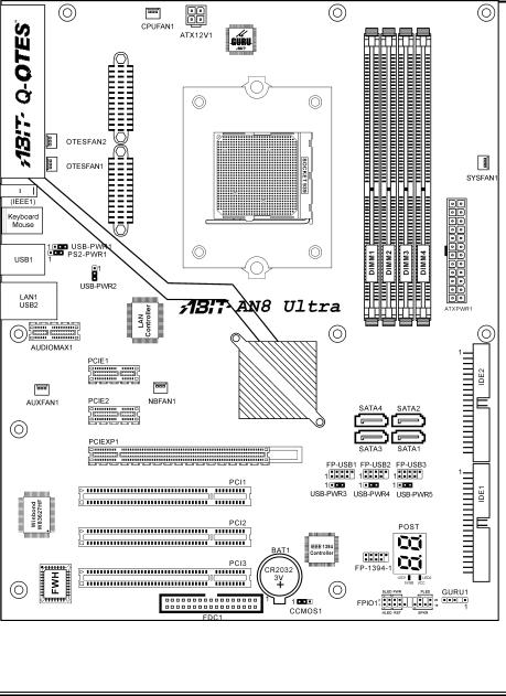
1-3. Layout Diagram (AN8 Ultra)
AN8 Series
Introduction |
1-5 |
|
|
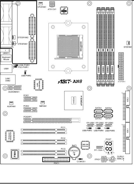
1-4. Layout Diagram (AN8-3rd Eye/AN8)
User’s Manual
1-6 |
Chapter 1 |
|
|
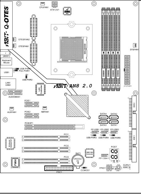
1-5. Layout Diagram (AN8 V2.0)
AN8 Series
Introduction |
1-7 |
|
|
1-6. Layout Diagram (AN8-V)
User’s Manual

1-8 |
Chapter 1 |
|
|
AN8 Series
Hardware Setup |
2-1 |
|
|
Chapter 2. Hardware Setup
Before the Installation: Turn off the power supply switch (fully turn off the +5V standby power), or disconnect the power cord before installing or unplugging any connectors or add-on cards. Failing to do so may cause the motherboard components or add-on cards to malfunction or damaged.
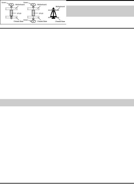
2-1. Install The Motherboard
Most computer chassis have a base with many mounting holes to allow a motherboard to be securely attached and at the same time, prevented from short circuits. There are two ways to attach the motherboard to the chassis base:
1.use with studs
2.or use with spacers
In principle, the best way to attach the board is to studs. Only if you are unable to do this should you attach the board with spacers. Line up the holes on the board with the mounting holes on the chassis. If the holes line up and there are screw holes, you can attach the board with studs. If the holes line up and there are only slots, you can only attach with spacers. Take the tip of the spacers and insert them into the slots. After doing this to all the slots, you can slide the board into
position aligned with slots. After the board has been positioned, check to make sure everything is OK before putting the chassis back on.
ATTENTION: To prevent shorting the PCB circuit, please REMOVE the metal studs or spacers if they are already fastened on the chassis base and are without mounting-holes on the motherboard to align with.
User’s Manual
2-2 |
Chapter 2 |
|
|
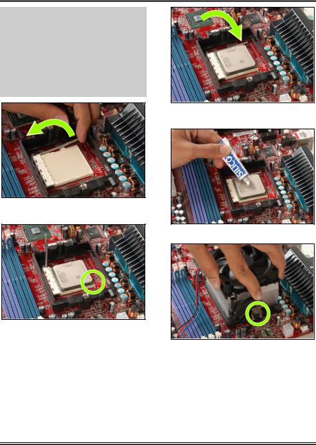
2-2. Install CPU, Heatsink and Fan Assembly
Please pay attention to the following notices before installing the CPU and heatsink/fan assembly.
1.Always use the processor with the Heatsink and Fan Assembly installed.
2.Do not touch the pins on the processor.
3.If you ever need to reinstall the Heatsink and fan Assembly, please clean the heatsink surface and apply new thermal interface material first.
1. Pull out the socket locking lever slightly, then lift it up.
2. Align the corner with triangle mark of the processor with the marking on the motherboard, and then place the processor vertical down into the socket.
3. Lower the locking lever to the fully locked position.
4.Apply thermal interface material.
5. Place the heatsink and fan assembly onto the retention frame. Match the heatsink clip with the socket mounting lug. Hook the spring clip to the mounting lug.
AN8 Series
|
Hardware Setup |
2-3 |
|
|
|
|
|
|
|
|
|
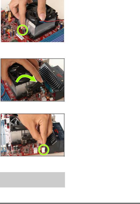
6. On the other side, push the retention clip straight down to lock into the plastic lug on the retention frame.
7. Turn the cam lever to lock into the retention frame.
8. Attach the four-pin power plug from the heatsink and fan assembly to the CPU FAN connector.
For detailed information on how to install your heatsink and fan assembly, please refer to the instruction manual that came packed with the heatsink and fan assembly you bought.
User’s Manual

2-4 |
Chapter 2 |
|
|
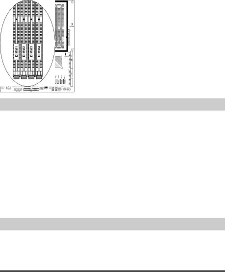
2-3. Install System Memory
This motherboard provides four 184-pin DDR DIMM slots for Single/Dual Channel DDR 400/333/266 memory modules with memory expansion size up to 4GB.
Table 2-1. Valid Memory Configurations
Bank |
Memory Module |
Total Memory |
|
|
|
Bank 0, 1 (DIMM1) |
256, 512MB, 1GB |
256MB ~ 1GB |
|
|
|
Bank 2, 3 (DIMM2) |
256, 512MB, 1GB |
256MB ~ 1GB |
|
|
|
Bank 4, 5 (DIMM3) |
256, 512MB, 1GB |
256MB ~ 1GB |
|
|
|
Bank 6, 7 (DIMM4) |
256, 512MB, 1GB |
256MB ~ 1GB |
|
|
|
|
Total System Memory |
256MB ~ 4GB |
|
|
|
Table 2-2. Unbuffered DIMM Support For AMD 939-pin Processor
Data Bus |
DIMM1 |
DIMM2 |
DIMM3 |
DIMM4 |
Default |
|
Setting |
||||||
|
|
|
|
|
||
|
|
|
|
|
|
|
|
Single rank |
N/A |
Empty |
N/A |
DDR400 |
|
|
|
|
|
|
|
|
|
Double rank |
N/A |
Empty |
N/A |
DDR400 |
|
|
|
|
|
|
|
|
|
Empty |
N/A |
Single rank |
N/A |
DDR400 |
|
64-bits |
|
|
|
|
|
|
Empty |
N/A |
Double rank |
N/A |
DDR400 |
||
(Single |
|
|
|
|
|
|
Single rank |
N/A |
Single rank |
N/A |
DDR400 |
||
Channel) |
||||||
|
Single rank |
N/A |
Double rank |
N/A |
DDR400 |
|
|
|
|
|
|
|
|
|
Double rank |
N/A |
Single rank |
N/A |
DDR400 |
|
|
|
|
|
|
|
|
|
Double rank |
N/A |
Double rank |
N/A |
DDR333 |
|
|
|
|
|
|
|
|
|
Single rank |
Single rank |
Empty |
Empty |
DDR400 |
|
|
|
|
|
|
|
|
|
Double rank |
Double rank |
Empty |
Empty |
DDR400 |
|
|
|
|
|
|
|
|
|
Empty |
Empty |
Single rank |
Single rank |
DDR400 |
|
128-bits |
|
|
|
|
|
|
Empty |
Empty |
Double rank |
Double rank |
DDR400 |
||
(Dual |
|
|
|
|
|
|
Single rank |
Single rank |
Single rank |
Single rank |
DDR400 |
||
Channel) |
||||||
|
Single rank |
Single rank |
Double rank |
Double rank |
DDR400 |
|
|
|
|
|
|
|
|
|
Double rank |
Double rank |
Single rank |
Single rank |
DDR400 |
|
|
|
|
|
|
|
|
|
Double rank |
Double rank |
Double rank |
Double rank |
DDR333 |
|
|
|
|
|
|
|
AN8 Series
Hardware Setup |
2-5 |
|
|
To reach the performance of Dual Channel DDR, the following rules must be obeyed:
•When installing TWO DIMM modules: Install DIMM modules of the same type and size for slots [DIMM1]+[DIMM2] or slots [DIMM3]+[DIMM4].
•When installing FOUR DIMM modules: Install DIMM modules of the same type and size for slots [DIMM1]+[DIMM2], and slots [DIMM3]+[DIMM4].
AN8 Ultra/AN8 3rd Eye/AN8/AN8 V2.0/AN8-V
NOTE: This illustration is based on the model AN8 Ultra. All other models except for AN8 SLI share the same connector, header and jumper positions.
AN8 SLI
NOTE: Usually there is no hardware or BIOS setup requires after adding or removing memory modules, but you will have to clear the CMOS memory first if any memory module related problem occurs.
User’s Manual
2-6 |
Chapter 2 |
|
|
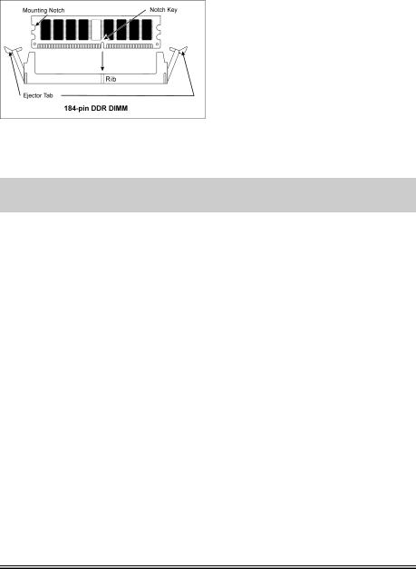
Power off the computer and unplug the AC power cord before installing or removing memory modules.
1.Locate the DIMM slot on the board.
2.Hold two edges of the DIMM module carefully, keep away of touching its connectors.
3.Align the notch key on the module with the rib on the slot.
4.Firmly press the module into the slots until the ejector tabs at both sides of the slot automatically snaps into the mounting notch. Do not force the DIMM module in with extra
force as the DIMM module only fit in one direction.
5.To remove the DIMM modules, push the two ejector tabs on the slot outward simultaneously, and then pull out the DIMM module.
ATTENTION: Static electricity can damage the electronic components of the computer or optional boards. Before starting these procedures, ensure that you are discharged of static electricity by touching a grounded metal object briefly.
AN8 Series
Hardware Setup |
2-7 |
|
|
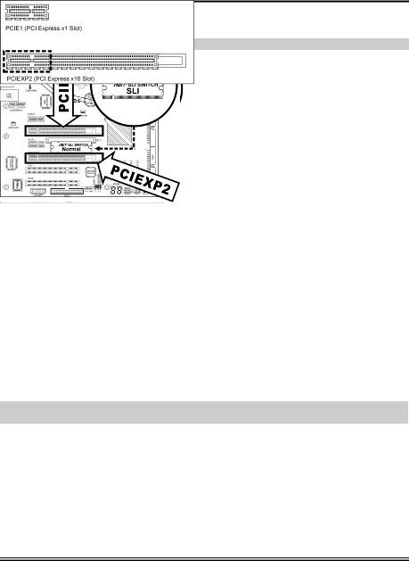
2-4. Install two Graphics Cards with NVIDIA SLI Technology
(AN8 SLI)
This motherboard supports the NVIDIA SLI (Scalable-Link-Interface) technology, allowing the operation of two identical (the same model from the same manufacturer) PCI Express x16 graphics cards.
NOTE: The NVIDIA SLI technology currently supports the Windows XP operating system only.
Normal Mode: Leave the SLI Switch to its default Normal mode and insert the graphics card into PCIEXP1 slot. The PCIEXP2 slot functions as a PCIE x1 slot under this mode.
SLI Mode: Switch the SLI Switch to SLI Mode and insert the SLI-ready graphics cards into PCIEXP1 and PCIEXP2 slots.
NOTE: When PCIEXP2 slot functions as a PCIE x1 slot under Normal mode, insert the PCIE x1 card into the marked area of PCIEXP2 slot.
This motherboard is factory pre-installed with an ABIT SLI switchboard. By the default “Normal” mode, this motherboard is set for one single graphics card operation. To operate two graphics cards on this motherboard, you will have to set the switchboard to “SLI” mode in advance.
•Prepare two identical NVIDIA certified, SLI-ready PCI Express x16 graphics cards.
•Make sure the graphics card driver supports the NVIDIA SLI technology. Download the latest driver form NVIDIA website (www.nvidia.com).
•Make sure your power supply unit is sufficient to provide the minimum power required.
User’s Manual
2-8 |
Chapter 2 |
|
|
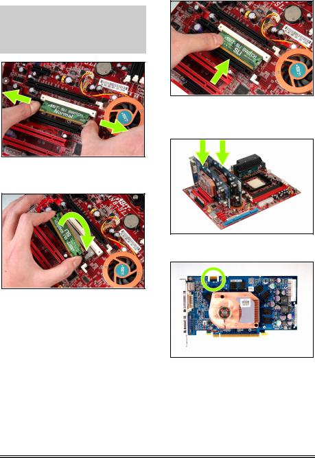
Please follow the instructions below to set the system to SLI mode and install your graphics cards.
NOTE: Please handle the switchboard with caution. Watch out for the sharp edges.
1. Simultaneously push the two retention clips at both ends outward to release the switchboard. Carefully pull the switchboard out of the slot.
2. Flip the switchboard over to the side labeled with “SLI”. Carefully insert the switchboard into the slot.
3. Slightly push down the switchboard until the retention clip snap into places. Make sure the switchboard is completely inserted into the slot.
4. Insert the two graphics cards into PCIEXP1 and PCIEXP2 slots on the motherboard.
5. There are goldfingers on your SLI Graphics Cards reserved for the SLI Bridge Connector.
AN8 Series
Hardware Setup |
2-9 |
|
|
6. Insert the SLI Bridge Connector into the SLI goldfingers on each graphics card.
7. The SLI bracket included in the package is used for supporting the SLI bridge connector and the two SLI graphics cards.
8. Insert the SLI bracket into the bracket slot between the graphics cards. Secure the SLI bracket and the graphics cards to the chassis with screws.
NOTE: The OTES SLIpstream that packed in the package is optional. Please refer to the Quick Installation Guide of the OTES SLIpstream if you wish to install it.
IMPORTANT: Please disable the following items in BIOS setup while running under SLI mode: All the “FanEQ controls” (CPU, NB, SYS, OTES1, OTES2 and AUX FanEQ Control) and “Cool ’n’ Quiet Technology”. The system may be unstable without doing so. Detail information about these items will be described in “Chapter 3. BIOS Setup”.
User’s Manual
2-10 |
Chapter 2 |
|
|
2-5. Connectors, Headers and Switches
Here we will show you all of the connectors, headers and switches, and how to connect them. Please read the entire section for necessary information before attempting to finish all the hardware installation inside the computer chassis. A complete enlarged layout diagram is shown in Chapter 1 for all the positions of connectors and headers on the board that you may refer to.
WARNING: Always power off the computer and unplug the AC power cord before adding or removing any peripheral or component. Failing to do so may cause severe damage to your motherboard and/or peripherals. Plug in the AC power cord only after you have carefully checked everything.
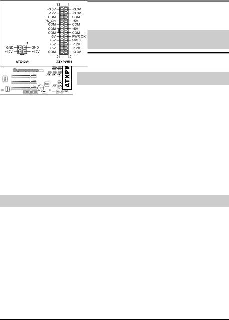
(1). ATX Power Input Connectors
This motherboard provides two power connectors to connect ATX12V power supplier.
NOTE: This 24-pin power connector “ATXPWR1” is compliant to the former 20-pin type. Pay attention to the orientation when attaching the power cord. (Pin-11, 12, 23, and 24 should be left un-connected).
AN8 Ultra/AN8 3rd Eye/AN8/AN8 V2.0/AN8-V
NOTE: This illustration is based on the model AN8 Ultra. All other models except for AN8 SLI share the same connector, header and jumper positions.
AN8 Series
Hardware Setup |
2-11 |
|
|
AN8 SLI
Note: It is recommended to connect to a power with 350W, 20A +5VDC capacity at least for heavily loaded system, and a 2A +5VSB capacity at least for supporting wake-up features.
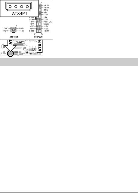
The auxiliary 12V power connector [ATX4P1] provides an additional power source for devices added on PCI Express slots. It is highly recommended to attach 12V power from the power supplier for the best system stability.
User’s Manual
2-12 |
Chapter 2 |
|
|
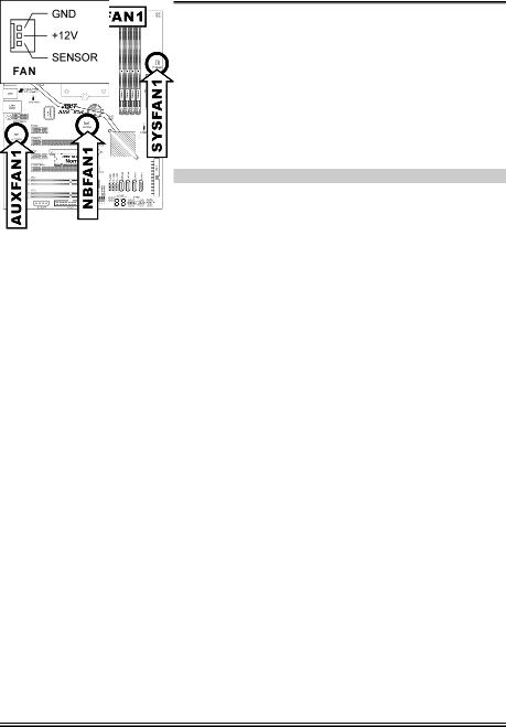
(2). FAN Power Connectors
These connectors each provide power to the cooling fans installed in your system.
•CPUFAN1: CPU Fan Power Connector
•SYSFAN1: System Fan Power Connector
•AUXFAN1: Auxiliary Fan Power Connector
•NBFAN1: Chipset Fan Power Connector
•OTESFAN1, OTESFAN2: OTES Fan Power Connector
WARNING: These fan connectors are not jumpers. DO NOT place jumper caps on these connectors.
AN8 Ultra/AN8 3rd Eye/AN8/AN8 V2.0/AN8-V |
AN8 SLI |
AN8 Series

Hardware Setup |
2-13 |
|
|
(3). CMOS Memory Clearing Header
This header uses a jumper cap to clear the CMOS memory.
•Pin 1-2 shorted (default): Normal operation.
•Pin 2-3 shorted: Clear CMOS memory.
WARNING: Turn the power off first (including the +5V standby power) before clearing the CMOS memory. Failing to do so may cause your system to work abnormally or malfunction.
AN8 Ultra/AN8 3rd Eye/AN8/AN8 V2.0/AN8-V
AN8 SLI
User’s Manual
2-14 |
Chapter 2 |
|
|
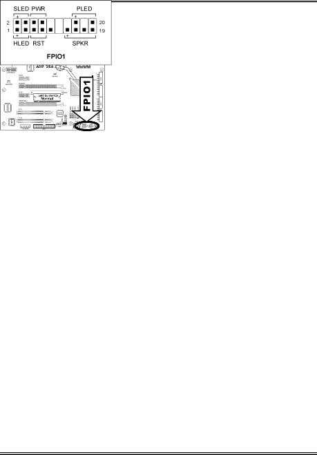
(4). Front Panel Switches & Indicators Headers
This header is used for connecting switches and LED indicators on the chassis front panel.
Watch the power LED pin position and orientation. The mark “+” aligning to the pin in the figure below stands for positive polarity for the LED connection. Please pay attention to connect these headers. A wrong orientation will simply cause the LED to not light, but a wrong connection of the switches could cause system malfunction.
AN8 Ultra/AN8 3rd Eye/AN8/AN8 V2.0/AN8-V AN8 SLI
•HLED (Pin 1, 3):
Connects to the HDD LED cable of chassis front panel.
•RST (Pin 5, 7):
Connects to the Reset Switch cable of chassis front panel.
•SPKR (Pin 13, 15, 17, 19):
Connects to the System Speaker cable of chassis.
•SLED (Pin 2, 4):
Connects to the Suspend LED cable (if there is one) of chassis front panel.
•PWR (Pin 6, 8):
Connects to the Power Switch cable of chassis front panel.
•PLED (Pin 16, 18, 20):
Connects to the Power LED cable of chassis front panel.
AN8 Series

Hardware Setup |
2-15 |
|
|
(5). Additional USB Port Headers
These headers each provide 2 additional USB 2.0 ports connection through a USB cable designed for USB 2.0 specifications.
AN8 Ultra/AN8 3rd Eye/AN8/AN8 V2.0/AN8-V
Pin |
Pin Assignment |
Pin |
Pin Assignment |
|
|
|
|
1 |
VCC |
2 |
VCC |
|
|
|
|
3 |
Data0 - |
4 |
Data1 - |
|
|
|
|
5 |
Data0 + |
6 |
Data1 + |
7 |
Ground |
8 |
Ground |
|
|
|
|
9 |
NC |
10 |
NC |
|
|
|
|
AN8 SLI
Pin |
Pin Assignment |
Pin |
Pin Assignment |
|
|
|
|
1 |
VCC |
2 |
VCC |
|
|
|
|
3 |
Data0 - |
4 |
Data1 - |
|
|
|
|
5 |
Data0 + |
6 |
Data1 + |
7 |
Ground |
8 |
Ground |
|
|
|
|
9 |
NC |
10 |
NC |
|
|
|
|
User’s Manual

2-16 |
Chapter 2 |
|
|
(6). Additional IEEE1394 Port Headers
This header provides one additional IEEE1394 port connection through an extension cable and bracket.
AN8 Ultra/AN8 3rd Eye/AN8/AN8 V2.0
Pin |
Pin Assignment |
Pin |
Pin Assignment |
|
|
|
|
1 |
TPA0 + |
2 |
TPA0 - |
|
|
|
|
3 |
GND |
4 |
GND |
|
|
|
|
5 |
TPB0 + |
6 |
TPB0 - |
7 |
+12V |
8 |
+12V |
|
|
|
|
9 |
NC |
10 |
GND |
|
|
|
|
AN8 SLI
Pin |
Pin Assignment |
Pin |
Pin Assignment |
1 |
TPA0 + |
2 |
TPA0 - |
|
|
|
|
3 |
GND |
4 |
GND |
|
|
|
|
5 |
TPB0 + |
6 |
TPB0 - |
|
|
|
|
7 |
+12V |
8 |
+12V |
9 |
NC |
10 |
GND |
|
|
|
|
AN8 Series
Hardware Setup |
2-17 |
|
|
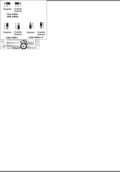
(7). Wake-up Header
These headers use a jumper cap to enable/disable the wake-up function.
AN8 Ultra/AN8 3rd Eye/AN8/AN8 V2.0/AN8-V
AN8 SLI
•PS2-PWR1:
Pin 1-2 shorted: Disable wake-up function support at Keyboard/Mouse port.
Pin 2-3 shorted (default): Enable wake-up function support at Keyboard/Mouse port.
•USB-PWR1:
Pin 1-2 shorted: Disable wake-up function support at USB1 port.
Pin 2-3 shorted (default): Enable wake-up function support at USB1 port.
•USB-PWR2:
Pin 1-2 shorted: Disable wake-up function support at USB2 port.
Pin 2-3 shorted (default): Enable wake-up function support at USB2 port.
User’s Manual

2-18 |
Chapter 2 |
|
|
•USB-PWR3:
Pin 1-2 shorted: Disable wake-up function support at FP-USB1 port.
Pin 2-3 shorted (default): Enable wake-up function support at FP-USB1 port.
•USB-PWR4:
Pin 1-2 shorted: Disable wake-up function support at FP-USB2 port.
Pin 2-3 shorted (default): Enable wake-up function support at FP-USB2 port.
•USB-PWR5:
Pin 1-2 shorted: Disable wake-up function support at FP-USB3 port.
Pin 2-3 shorted (default): Enable wake-up function support at FP-USB3 port.
AN8 Series
Loading...