


 Loading...
KV8-MAX3
Socket 754 System Board
User’s Manual
4200-0389-13 Rev. 1.02

Copyright and Warranty Notice
The information in this document is subject to change without notice and does not represent a commitment on part of the vendor, who assumes no liability or responsibility for any errors that may appear in this manual.
No warranty or representation, either expressed or implied, is made with respect to the quality, accuracy or fitness for any particular part of this document. In no event shall the manufacturer be liable for direct, indirect, special, incidental or consequential damages arising from any defect or error in this manual or product.
Product names appearing in this manual are for identification purpose only and trademarks and product names or brand names appearing in this document are the property of their respective owners.
This document contains materials protected under International Copyright Laws. All rights reserved. No part of this manual may be reproduced, transmitted or transcribed without the expressed written permission of the manufacturer and authors of this manual.
If you do not properly set the motherboard settings, causing the motherboard to malfunction or fail, we cannot guarantee any responsibility.
KV8-MAX3

Table Of Contents
KV8-MAX3 ...................................................................... |
2 |
|||
KV8-MAX3 ...................................... |
4 |
|||
KV8-MAX3 Schnellinstallationsanleitung............................................. |
6 |
|||
KV8-MAX3 Guide d’Installation Rapide .............................................. |
8 |
|||
Краткое руководство по установке KV8-MAX3 ............................. |
10 |
|||
Guida all’installazione veloce Scheda madre KV8-MAX3................. |
12 |
|||
Chapter 1. |
Introduction .......................................................................... |
1-1 |
||
1-1. |
Features & Specifications ........................................................................ |
1-1 |
||
1-2. |
Layout Diagram ....................................................................................... |
1-3 |
||
Chapter 2. |
Hardware Setup.................................................................... |
2-1 |
||
2-1. |
Install The Motherboard........................................................................... |
2-1 |
||
2-2. Install CPU and Heatsink......................................................................... |
2-2 |
|||
2-3. |
Install System Memory ............................................................................ |
2-3 |
||
2-4. Connectors, Headers and Switches .......................................................... |
2-5 |
|||
|
(1). |
|
ATX Power Input Connectors........................................................ |
2-5 |
|
(2). |
|
FAN Connectors............................................................................. |
2-6 |
|
(3). |
|
CMOS Memory Clearing Header .................................................. |
2-7 |
|
(4). |
|
Wake-up Header............................................................................. |
2-8 |
|
(5). |
|
Front Panel Switches & Indicators Headers .................................. |
2-9 |
|
(6). |
|
Additional USB Port Headers...................................................... |
2-10 |
|
(7). |
|
Additional IEEE1394 Port Header............................................... |
2-11 |
|
(8). |
|
Front Panel Audio Connection Header ........................................ |
2-12 |
|
(9). |
|
Internal Audio Connectors ........................................................... |
2-13 |
|
(10). |
Accelerated Graphics Port Slot.................................................... |
2-13 |
|
|
(11). |
Floppy Disk Drive Connector...................................................... |
2-14 |
|
|
(12). |
IDE Connectors............................................................................ |
2-15 |
|
|
(13). |
POST Code Display ..................................................................... |
2-16 |
|
|
(14). |
Serial ATA Connectors ................................................................. |
2-17 |
|
|
(15). |
Status Indicators........................................................................... |
2-18 |
|
|
(16). |
System Management Bus Headers............................................... |
2-19 |
|
|
(17). |
Back Panel Connectors ................................................................ |
2-20 |
|
User’s Manual

Chapter 3. |
BIOS Setup............................................................................ |
3-1 |
|
3-1. |
SoftMenu Setup........................................................................................ |
3-3 |
|
3-2. |
Standard CMOS Features......................................................................... |
3-5 |
|
3-3. |
Advanced BIOS Features......................................................................... |
3-8 |
|
3-4. |
Advanced Chipset Features.................................................................... |
3-10 |
|
3-5. |
Integrated Peripherals ............................................................................ |
3-14 |
|
3-6. |
Power Management Setup ..................................................................... |
3-17 |
|
3-7. |
PnP/PCI Configurations......................................................................... |
3-19 |
|
3-8. |
PC Health Status .................................................................................... |
3-21 |
|
3-9. |
Load Fail-Safe Defaults ......................................................................... |
3-24 |
|
3-10. |
Load Optimized Defaults ....................................................................... |
3-24 |
|
3-11. |
Set Password .......................................................................................... |
3-24 |
|
3-12. |
Save & Exit Setup .................................................................................. |
3-24 |
|
3-13. |
Exit Without Saving............................................................................... |
3-24 |
|
Appendix A. |
Install VIA 4-in-1 Driver ................................................................. |
A-1 |
|
Appendix B. |
Install Audio Driver ......................................................................... |
B-1 |
|
Appendix C. |
Install LAN Driver ........................................................................... |
C-1 |
|
Appendix D. |
Install VIA USB 2.0 Driver ............................................................. |
D-1 |
|
Appendix E. |
Install VIA Serial ATA RAID Driver.............................................. |
E-1 |
|
Appendix F. |
Install Silicon Serial ATA RAID Driver ......................................... |
F-1 |
|
Appendix G. |
Install ABIT µGuru Driver.............................................................. |
G-1 |
|
Appendix H. |
POST Code Definition ..................................................................... |
H-1 |
|
Appendix I. |
Troubleshooting (Need Assistance?)................................................ |
I-1 |
|
Appendix J. |
How to Get Technical Support ......................................................... |
J-1 |
|
KV8-MAX3
1
User’s Manual
2 |
KV8-MAX3 |
|
|
|
|
KV8-MAX3
已包覆在隨本主機板所附的驅動程式與應用光碟之中。
Zero Insertion Force ZIF Socket 754 AMD Socket 754 CPUCPUSocket 754
CPU
1.Socket 754 CPU90
2.CPU CPUCPUCPU
4. 的固定腳。
5.CPU
7. 上的CPU
倍頻的數值。
KV8-MAX3
KV8-MAX3 |
3 |
|
|
|
|
您可以使用塑膠墊片來讓螺絲與主機板的PCB
1.DIMM
2.DIMM
3.DIMM
4.DIMMDIMM
DIMMDIMM
5.DIMM DIMM DIMM
SCSI AGP
ATX12V
ATX ATX12V
BIOS
BIOS
User’s Manual
4 |
KV8-MAX3 |
|
|
|
|
KV8-MAX3
ーズマニュアルはこのマザーボードに付属するドライバとユーティリティCD
ZIF ()Socket 754 AMD Socket 754 CPU
CPUSocket 754
CPU
1.Socket 754 CPU
2.CPUCPU CPUCPU
5.CPU
7. クタをマザーボードのCPU-FAN
KV8-MAX3
KV8-MAX3 |
5 |
|
|
|
|
RAM
1.DIMM
2.DIMM 2
DIMM DIMM
5.DIMM 2
ります。これらの手順を開始する前に、アースされた金属物体に軽く触れて静電気を必ず放電し てください。
プラグは、通常マザーボードにあるコネクタに1 1 SCSI AGP
ATX12V
ATX12V
BIOS
BIOS Setup
User’s Manual
6 |
KV8-MAX3 Schnellinstallationsanleitung |
|
|
KV8-MAX3 Schnellinstallationsanleitung
Beziehen Sie sich bitte für detaillierte Informationen über diese Hauptplatine auf die vollständige Version des Benutzerbuchs. Diese Schnellinstallationsanleitung ist für erfahrene Systemaufbauer gedacht. Ist es Ihr erster Versuch ein Computersystem aufzubauen, dann empfehlen wir Ihnen zuerst das vollständige Benutzerhandbuch zu lesen oder einen Techniker zum Aufbauen des Systems zu Hilfe zu holen. (Ein komplettes Handbuch finden Sie auf der CD mit den Treibern und Hilfsprogrammen, die diesem Motherboard beiliegt.)
Installieren des Prozessors
Dieses Motherboard besitzt einen ZIF- (Nullkraft-)
Sockel 754 für die Installation einer AMD Sockel 754
CPU. Der von Ihnen erworbenen CPU sollte ein
Kühlkörper, ein Lüfter, ein Retentionsrahmen und eine
Blackplate beigelegt sein. Kaufen Sie andernfalls eine
CPU, die speziell für Sockel 754 ausgelegt ist.
Bitte schauen Sie sich zur Installation von CPU und
Kühlblech diese Abbildung an. (Nur zur Referenz - Ihr
Kühlblech & Lüftergefüge könnten sich von dieser
Abbildung unterscheiden.)
1.Finden Sie den Sockel 754 auf diesem Motherboard. Ziehen Sie den CPU-Freigabehebel zur Entriegelung zur Seite und ziehen Sie ihn dann ganz hoch.
2.Stecken Sie den Prozessor mit der Stiftseite nach unten in den CPU-Sockel. Stecken Sie die CPU nicht gewaltsam hinein; sie passt nur in eine Richtung. Schließen Sie den CPU-Freigabehebel.
3.Richten Sie die Backplate-Distanzstifte mit den Montagelöcher des Motherboards aus. Setzen Sie die Backplate auf das Motherboard.
4.Legen Sie den Retentionsrahmen auf das Motherboard und richten Sie ihn mit den Backplate-Distanzstiften aus.
5.Setzen Sie den Kühlkörper auf die CPU, wobei Sie darauf achten müssen, dass er gut auf den Retentionsrahmen passt.
6.Haken Sie beide Seiten der Federklemme in die Montagezapfen des Retentionsrahmens ein. Ziehen Sie die Schrauben fest an, bis die Federklemme komplett angebracht ist.
7.Befestigen Sie den Lüfteranschluss des Kühlkörpers und des Lüftersets am CPU-LÜFTER-Anschluss auf dem Motherboard.
Achtung: Vergessen Sie nicht, die korrekte Busfrequenz und -Multiplikator für Ihren Prozessor einzustellen.
KV8-MAX3
KV8-MAX3 Schnellinstallationsanleitung |
7 |
|
|
Installieren der Hauptplatine im Gehäuse
Nach der Installation des Prozessors können Sie anfangen die Hauptplatine im Computergehäuse zu befestigen. Die meisten Gehäuse haben eine Bodenplatte, auf der sich eine Reihe von Befestigungslöcher befinden, mit deren Hilfe Sie die Hauptplatine sicher verankern können und zugleich Kurzschlüsse verhindern. Verwenden Sie entweder die Dübeln oder die Abstandhalter, um die Hauptplatine auf der Bodenplatte des Gehäuses zu befestigen.
Installation der RAM-Module
1.Finden Sie den DIMM-Steckplatz auf dem Board.
2.Halten Sie ie beiden Ränder des DIMM-Moduls vorsichtig fest, wobei Sie darauf achten, nicht die Anschlüsse zu berühren.
3.Richten Sie die Nut am Modul mit der Erhöhung am Steckplatz aus.
4.Drücken Sie das Modul fest in die Steckplätze, bis die Auswurflaschen zu beiden Seiten des Steckplatzes
automatisch in die Befestigungskerbe einschnappen. Wenden Sie keine Gewalt beim Einsetzen des DIMM-Moduls an; es paßt nur in eine Richtung hinein.
5.Zum Ausbau der Module drücken Sie die beiden Auswurflaschen auf dem Steckplatz nach außen zusammen und ziehen das Modul heraus.
Anschlüsse, Sockel, Schalter und Adapter
Im Inneren des Gehäuses findet man in jedem Computer viele Kabel und Stecker, die angeschlossen werden müssen. Diese Kabel und Stecker werden normalerweise einzeln mit den Anschlüssen auf der Hauptplatine verbunden. Sie müssen genau auf die Anschlussorientierung der Kabel achten und, wenn vorhanden, sich die Position des ersten Pols des Anschlusses merken. Wenn Sie Adapter wie z.B. SCSI-Adapter, AGP-Adapter usw. installieren, befestigen Sie bitte die Adapter immer mit Hilfe der Schrauben auf die Rückseite des Computergehäuses.
Für detaillierte Informationen beziehen Sie sich bitte auf das vollständige Benutzerhandbuch.
Verbinden der Netzstecker mit dem ATX12V-Anschluss
Denken Sie daran, den Anschluss des ATX-Netzteils fest in das Ende mit dem ATX12V-Anschluss zu drücken, um eine feste Verbindung zu garantieren.
BIOS-Setup
Schalten Sie nach der vervollständigten Hardwareinstallation den Computer ein und gehen zur Option im BIOS, um die Prozessorparameter einzustellen. Für detaillierte Informationen beziehen Sie sich bitte auf das vollständige Benutzerhandbuch.
User’s Manual
8 |
KV8-MAX3 Guide d’Installation Rapide |
|
|
KV8-MAX3 Guide d’Installation Rapide
Pour des informations relatives à cette carte mère plus détaillées, veuillez vous référer à notre version complète du manuel utilisateur. Ce guide d’installation rapide est créé pour les assembleurs système expérimentés. S’il s’agit de votre premier essai pour installer un ordinateur, nous vous suggérons de lire d’abord le manuel en version complète ou de demander l’aide d’un technicien pour vous aider à configurer le système ordinateur. (Un manuel de l'utilisateur complet est disponible en naviguant dans le CD des pilotes et utilitaires fournis avec la carte mère.)
Installer le Processeur
Cette carte mère dispose d’un support Socket 754 ZIF (Zero Insertion Force) permettant d’installer les processeurs AMD sur Socket 754. Le processeur que vous avez acheté doit comprendre un kit dissipateur thermique, un ventilateur de refroidissement, un cadre de support et une plaque arrière. Dans le cas contraire, veuillez vous procurer des éléments spécialement conçus pour le Socket 754.
Veuillez vous référer à la figure illustrée ci-contre pour installer le processeur et le dissipateur thermique. (Démonstration donnée à titre indicatif uniquement. L’assemblage de votre dissipateur thermique et de votre ventilateur peut ne pas être tout à fait identique à celui-ci.)
1.Repérez le support Socket 754 situé sur cette carte mère. Tirez le levier de maintien du processeur vers l’extérieur pour le libérer puis soulevez-le complètement vers le haut.
2.Installez le processeur avec ses broches faisant face au support pour processeur. Ne forcez pas en insérant le processeur; il ne peut s’insérer que dans une seule direction. Rabattez le levier de maintien du processeur.
3.Alignez les entretoises situées sur la plaque arrière avec les trous de montage se trouvant sur la carte mère. Mettez la plaque arrière en place sur la carte mère.
4.Mettez le cadre de support sur la carte mère et alignez-le avec les entretoises de la plaque arrière.
5.Installez le dissipateur thermique sur le dessus du processeur et assurez-vous qu’il s’insère correctement sur le cadre de support.
6.Accrochez les deux côtés de la bride de fixation sur les onglets de fixation du cadre de support. Serrez les vis jusqu’à ce que les deux côtés de la bride de fixation soient complètement bloqués.
7.Connectez le connecteur ventilateur de l’assemblage Dissipateur Thermique et Ventilateur au connecteur ventilateur pour processeur situé sur la carte mère.
KV8-MAX3
KV8-MAX3 Guide d’Installation Rapide |
9 |
|
|
Attention: N’oubliez pas de programmer la fréquence de bus correcte et le multiple pour votre processeur.
Installer la Carte Mre dans le Châssis
Une fois que vous aurez installé le processeur sur la carte mère, vous pourrez commencer à fixer la carte mère sur le châssis. Tout d’abord, vous avez besoin de fixer la carte mère sur le châssis. La plupart des châssis d’ordinateur possèdent une base sur laquelle il y a nombreux trous de montage permettant à la carte mère d’être fixée fermement, et en même temps d’éviter les court-circuits. Utilisez les talons ou les entretoises fixés sur le châssis pour fixer la carte mère.
Installer des Modules RAM
1.Localisez le socle DIMM sur la carte.
2.Maintenez les deux bords du module DIMM avec précaution, en évitant de toucher ses connecteurs.
3.Alignez la touche du cran avec la ligne sur le socle.
4.Pressez fermement le module dans les socles jusqu’à ce que les languettes d’éjection sur les deux côtés du socle aillent automatiquement dans le cran de montage. Ne forcez pas à l’excès sur le module DIMM car celui-ci ne peut aller que selon une seule orientation.
5.Pour enlever des modules DIMM, pressez simultanément les deux languettes d’éjection sur le socle, puis sortez le module DIMM.
Attention: L’électricité statique risque d’endommager les composants électroniques de l’ordinateur ou des cartes optionnelles. Avant de commencer ces procédures, assurez-vous de bien décharger toute l’électricité statique en touchant rapidement un objet métallique relié au sol.
Connecteurs, Socles de connexion, Interrupteurs et Adaptateurs
A l’intérieur du boîtier de n’importe quel ordinateur il y a plusieurs câbles et prises qui doivent être connectés. Ces câbles et prises sont habituellement connectés les uns après les autres aux connecteurs situés sur la carte mère. Vous avez besoin de faire attention au sens de connexion des câbles et, s’il y a lieu, remarquez la position de la première broche du connecteur. Vous installerez certains adaptateurs pour des besoins spéciaux, tels adaptateurs SCSI, adaptateurs AGP, etc. Lorsque vous les installez dans les emplacements situés sur la carte mère, veuillez les fixer sur le panneau arrière du châssis à l'aide des vis.
Pour les informations détaillées, veuillez vous référer au manuel utilisateur en version complète.
Brancher les connecteurs d'alimentation dans les connecteurs ATX12V
Souvenez-vous que vous devez pousser le connecteur de votre alimentation fermement dans le connecteur ATX12V pour assurer une bonne connexion.
Configuration du BIOS
Une fois le matériel installé complètement, démarrez l'ordinateur et allez sur l'item dans le BIOS pour configurer les paramètres du processeur. Pour les informations détaillées, veuillez vous référer à la version complète du manuel utilisateur.
User’s Manual
10 |
Краткое руководство по установке KV8-MAX3 |
|
|
Краткое руководство по установке KV8-MAX3
Более подробные сведения о материнской плате приведены в руководстве пользователя. Краткое руководство по установке предназначено для опытных специалистов. Если вы собираете компьютер впервые, ознакомьтесь сперва с руководством пользователя или попросите техника помочь в настройке компьютерной системы.
Установка процессора
Данная системная плата снабжена разъёмом Socket 754 ZIF (нулевое усилие вставки) для установки процессоров AMD Socket 754. Купленный вами процессор должен поставляться вместе с радиатором, вентилятором охлаждения, монтажной рамкой и пластиной для монтажа с обратной стороны. Если в комплекте с купленным вами процессором указанные выше детали отсутствуют, вам необходимо их приобрести.
Для установки процессора и радиатора, посмотрите пожалуйста на рисунок, показанный на этой странице. (Только для справочной работы. Ваш радиатор и комплект вентилятора может быть не точно такой же как показанный рисунок здесь.)
1.Найдите на системной плате разъём Socket 754. Потяните рычаг деблокировки процессора в сторону и наверх.
2.Вставьте выводы процессора в гнёзда разъёма. Не прилагайте излишних усилий! Процессор вставляется только в одном положении. Заблокируйте процессор при помощи рычага деблокировки процессора.
3.Сопоставьте ограничительные выступы на монтажной пластине с отверстиями в системной плате. Пластина должна размещаться под системной платой.
4.Положите монтажную рамку на системную плату. Проверьте соответствие монтажных отверстий платы и пластины с обратной стороны системной платы.
5.Установите радиатор на поверхность процессора. Радиатор должен плотно входить в монтажную рамку.
6.Зацепите пружинный держатель радиатора за выступы, расположенные на монтажной рамке. Затягивайте винты, пока пружинный держатель не зафиксируется.
7.Вывод вентилятора охлаждения подключите к разъёму на системной плате, предназначенному для системы охлаждения процессора.
KV8-MAX3

Краткое руководство по установке KV8-MAX3 |
11 |
|
|
Внимание: Установите соответствующие частоту и кратность шины процессора.
Установка материнской платы в корпус
После установки процессора на материнскую плату можно начинать установку материнской платы в корпус. Большая часть корпусов оборудована основанием, в котором проделаны монтажные отверстия, которые позволяют надежно закрепить материнскую плату и предотвратить короткие замыкания. Для крепления материнской платы к основанию используются винты и прокладки.
Установка модулей памяти
1.Найдите на системной плате разъем для модулей памяти DIMM.
2.Аккуратно, за два конца, возьмите модуль памяти, не касаясь контактов.
3.Совместите выемку в модуле памяти с выступом в разъеме.
4.Нажмите на модуль так, чтобы лепестки выталкивателя с обеих сторон разъема
автоматически защелкнулись и вошли в пазы. Не применяйте при установке излишнюю силу. Модуль входит в разъем только в одном положении.
5.Для извлечения модулей памяти DIMM одновременно нажмите на лепестки выталкивателя и вытащите модуль.
Внимание: Статическое электричество может стать причиной выхода из строя электронных компонентов компьютера. Перед началом данной процедуры снимите с себя статический заряд, коснувшись заземленного металлического предмета.
Разъемы, переключатели и адаптеры
Внутри корпуса компьютера необходимо расположены несколько кабелей и вилок, которые необходимо подключить. Обычно эти кабели подключаются к разъемам, расположенным на материнской плате. При подключении любого кабеля необходимо обращать внимание на расположение первого контакта разъема. Для особых целей могут потребоваться специальные адаптеры, например, адаптер SCSI, адаптер AGP и т.п.. При установке адаптеров в гнезда материнской платы закрепите их на задней панели с помощью винтов.
За более подробной информацией обращайтесь к полному руководству пользователя.
Подключение кабелей питания к разъемам ATX12V
Обратите внимание, разъем блока питания ATX необходимо вставить в разъем ATX12V до упора, чтобы обеспечить надежное соединение.
Настройка BIOS
По окончании установки аппаратуры включите питание и перейдите в меню BIOS Setup, чтобы настроить параметры процессора. За более подробной информацией обращайтесь к руководству пользователя.
User’s Manual
12 |
Guida all’installazione veloce Scheda madre KV8-MAX3 |
|
|
Guida all’installazione veloce Scheda madre KV8-MAX3
Per maggiori e dettagliate informazioni su questa scheda madre si prega di fare riferimento alla versione integrale del Manuale utente. Questa guida all’installazione veloce è intesa per costruttori esperi di sistemi. Se questa è la prima volta che si cerca di installare un sistema, si consiglia di leggere, innanzi tutto, la versione integrale del manuale oppure di chiedere aiuto ad un tecnico per l’installazione.
Installazione del processore
Questa scheda madre fornisce una presa Socket 754 ZIF (Zero Insertion Force: forza d’inserimento zero) per installare la CPU AMD Socket 754. La CPU che è stata acquistata dovrebbe essere dotata di dispersore di colare, ventolina di raffreddamento, telaio di trattenimento e piastra posteriore. In caso contrario è necessario acquistare gli elementi suddetti progettati specificatamente per la Socket 754.
Per il montaggio della CPU e del termodispersore, consultare la figura accanto. Si noti che il gruppo termodispersore-ventola illustrati possono non essere identici a quelli effettivamente da montare.
1.Ubicare la presa 754 sulla scheda madre. Tirare la levetta di rilascio della CPU verso l’esterno per sbloccare la CPU, poi sollevarla completamente.
2.Lasciare cadere il processore, con i pin rivolti verso il basso, nella presa CPU. Non sforzare per inserire la CPU perché si adatta solamente in una posizione. Chiudere la levetta di rilascio CPU.
3.Allineare i fermi della piastra posteriore con i fori di montaggio sulla scheda madre. Porre la piastra sulla scheda madre.
4.Porre il telaio di trattenimento sulla scheda madre ed allinearlo con i fermi della piastra.
5.Porre il disperso di calore sopra la CPU ed assicurarsi che si adatti in modo appropriato sul telaio di trattenimento.
6.Agganciare entrambi i lati del fermaglio a molla sui supporti di montaggio del telaio di trattenimento. Stringere le viti finché il fermaglio a molla è installato completamente.
7.Attaccare il connettore del gruppo dispersore di calore e ventolina al connettore CPU-FAN sulla scheda madre.
Attenzione: Non dimenticare di impostare la corretta frequenza multipla e BUS per il processore.
KV8-MAX3
Guida all’installazione veloce Scheda madre KV8-MAX3 |
13 |
|
|
Installazione della scheda madre sul telaio
Dopo avere installato il processore sulla scheda madre si può iniziare a fissare la scheda madre sul telaio. Innanzi tutto è necessario fissare la scheda madre al telaio. La maggior parte dei telai ha una base sulla quale sono presenti diversi fori di montaggio che permettono di fissare in modo accurato la scheda madre e, allo stesso tempo, di prevenire corto circuiti. Impiegare le borchie o gli spaziatori attaccati al telaio per fissare la scheda madre.
Installare i moduli RAM
1.Ubicare gli alloggiamenti DIMM sulla scheda.
2.Tenere con delicatezza i lati del modulo DIMM senza toccare i connettori.
3.Allineare la tacca sul modulo con la nervatura dell’alloggiamento.
4.Premere con fermezza il modulo nell’alloggiamento finché le linguette d’espulsione su entrambi i lati dell’alloggiamento scattano sulla tacca di montaggio.
Non forzare eccessivamente il modulo DIMM perché quest’ultimo si adatta solamente in una direzione.
5.Per rimuovere i moduli DIMM spingere contemporaneamente le due linguette d’espulsione sull’alloggiamento, poi estrarre il modulo DIMM.
Attenzione: L’elettricità statica può danneggiare i componenti elettronici del computer o delle schede. Prima di iniziare queste procedure, assicurarsi di avere scaricato completamente l’elettricità statica toccando brevemente un oggetto metallico con massa a terra.
Connettori, collettori, interruttori ed adattatori
All’interno della copertura di ogni computer ci sono diversi cavi e prese che devo essere collegati. Questi cavi e prese sono solitamente collegati uno ad uno ai connettori situati sulla scheda madre. E’ necessario prestare particolare attenzione a qualunque orientamento del collegamento che possono avere i cavi e, se necessario, notare la posizione del primo pin del connettore. Si installeranno alcuni adattatori per particolari necessità quali l’adattatore SCSI, AGP, eccetera. Quando si installano gli adattatori sugli slot della scheda madre, si ricorda di fissarli con le viti anche sul pannello posteriore del telaio.
Per informazioni dettagliate si prega di fare riferimento alla versione integrale del Manuale utente.
Collegamento dei connettori d’alimentazione ai connettori ATX12V
Ricordarsi che è necessario spingere con fermezza fino in fondo il connettore della sorgente d’alimentazione ATX al connettore ATX12V, assicurando così un buon collegamento.
Impostazione BIOS
Quando l’hardware è stato installato completamente, accendere il computer ed andare alla voce BIOS per impostare i parametri del processore. Per informazioni dettagliate si prega di fare riferimento alla versione integrale del Manuale utente.
User’s Manual
14
KV8-MAX3

Introduction |
1-1 |
|
|
Chapter 1. Introduction
1-1. Features & Specifications
1.CPU
•Supports AMD Socket 754 Athlon 64 CPU with 800 MHz HyperTransport
2.Chipset
•VIA K8T800 + VT8237
•Supports Advanced Configuration and Power Management Interface (ACPI)
•Accelerated Graphics Port connector supports AGP 8X/4X (0.8V/1.5V)
3.Memory
•72-bit memory controller supports DDR at 266, 333 and 400MHz (ECC)
•Support 3 DIMM up to 2GB Max.
•Support 3 DIMM DDR 333
•Support 2 DIMM DDR 400
4.SATA
•Supports SATA data transfer rates at 150 MB/s (1.5G bps)
5.2nd SATA RAID
•On board Serial ATA RAID PCI Controller
•Supports 4 x SATA 150 RAID 0/1/0+1
6.LAN
•On board 10/100/1000M LAN Controller
7.IEEE 1394a
•Supports IEEE 1394a at 400/200/100 Mb/s transfer rate
8.Audio
•Onboard 6-Channel AC 97 CODEC
•Professional digital audio interface supports S/PDIF Input/Output
9.ABIT Engineered
•ABIT µGuruTM Technology
•ABIT SoftMenuTM Technology
•ABIT FanEQTM Technology
•CPU ThermalGuardTM Technology
User’s Manual

1-2 |
Chapter 1 |
|
|
10.Internal I/O Connectors
•1x AGP 8X/4X slot
•5x PCI slots
•1x floppy port supports up to 2.88MB
•2x Ultra DMA 133/100/66/33 connectors
•6x Serial ATA 150 RAID connectors
•2x USB headers
•2x IEEE 1394a headers
•1x CD-IN, 1x AUX-IN header
11.Back Panel I/O
•1x PS/2 keyboard, 1x PS/2 mouse
•1x S/PDIF In connector
•1x S/PDIF Out connector
•AUDIO1 connector (Rear-Left / Rear-Right, Center/Subwoofer)
•AUDIO2 connector (Mic-In, Line-In, Front-Left/Front-Right)
•2x USB, 1x IEEE 1394a Connector
•2x USB, 1x RJ-45 LAN Connector
12.Miscellaneous
•ATX form factor
•Hardware Monitoring – Including Fan speed, Voltages, CPU and system temperature
Specifications and information contained herein are subject to change without notice.
KV8-MAX3

Introduction |
1-3 |
|
|
1-2. Layout Diagram
User’s Manual

1-4 |
Chapter 1 |
|
|
KV8-MAX3
Hardware Setup |
2-1 |
|
|
Chapter 2. Hardware Setup
Before the Installation: Turn off the power supply switch (fully turn off the +5V standby power), or disconnect the power cord before installing or unplugging any connectors or add-on cards. Failing to do so may cause the motherboard components or add-on cards to malfunction or damaged.
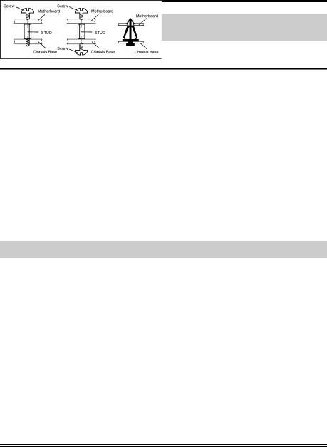
2-1. Install The Motherboard
Most computer chassis have a base with many mounting holes to allow motherboard to be securely attached on and at the same time, prevented from short circuits. There are two ways to attach the motherboard to the chassis base:
1.use with studs
2.or use with spacers
In principle, the best way to attach the board is to use with studs. Only if you are unable to do this should you attach the board with spacers. Line up the holes on the board with the mounting holes on the chassis. If the holes line up and there are screw holes, you can attach the board with studs. If the holes line up and there are only slots, you can only attach with spacers. Take the tip of the spacers and insert them into the slots. After doing this to all the slots, you can slide the board into
position aligned with slots. After the board has been positioned, check to make sure everything is OK before putting the chassis back on.
ATTENTION: To prevent shorting the PCB circuit, please REMOVE the metal studs or spacers if they are already fastened on the chassis base and are without mounting-holes on the motherboard to align with.
User’s Manual
2-2 |
Chapter 2 |
|
|
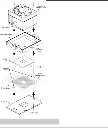
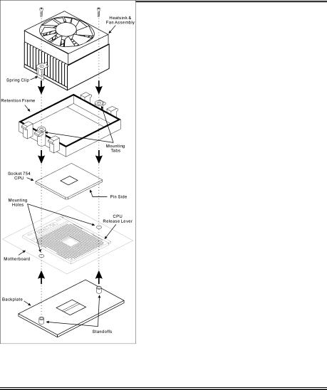
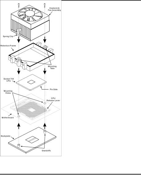
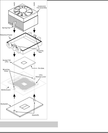
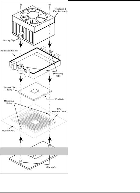
2-2. Install CPU and Heatsink
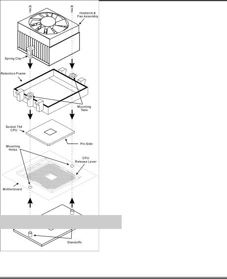
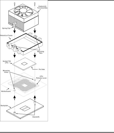
This motherboard provides a ZIF (Zero Insertion Force) Socket 754 to install AMD Socket 754 CPU. The CPU you bought should contain with a kit of heatsink, cooling fan, retention frame and blackplate. If that’s not the case, buy one specially designed for Socket 754.
Please refer to the figure shown here to install CPU and heatsink. (For reference only. Your Heatsink & Fan Assembly may not be exactly the same as this one.)
1.Locate the Socket 754 on this motherboard. Pull the CPU release lever sideways to unlatch and then raise it all the way up.
2.Drop the processor with its pin side down into the CPU socket. Do not use extra force to insert CPU; it only fits in one direction. Close the CPU release lever.
3.Align the Backplate Standoffs with the mounting holes on motherboard. Position the backplate onto motherboard.
4.Place the Retention Frame onto the motherboard and align it with the Backplate Standoffs.
5.Place heatsink on top of CPU, and make sure the heatsink fits properly on the retention frame.
6.Hook both sides of the Spring Clip onto the Mounting Tabs of Retention Frame. Tighten screws until the Spring Clip is fully installed.
7.Attach the fan connector of Heatsink & Fan Assembly with the CPU-FAN connector on the motherboard.
ATTENTION: Do not forget to set the correct bus frequency and multiple for your processor.
KV8-MAX3

Hardware Setup |
2-3 |
|
|
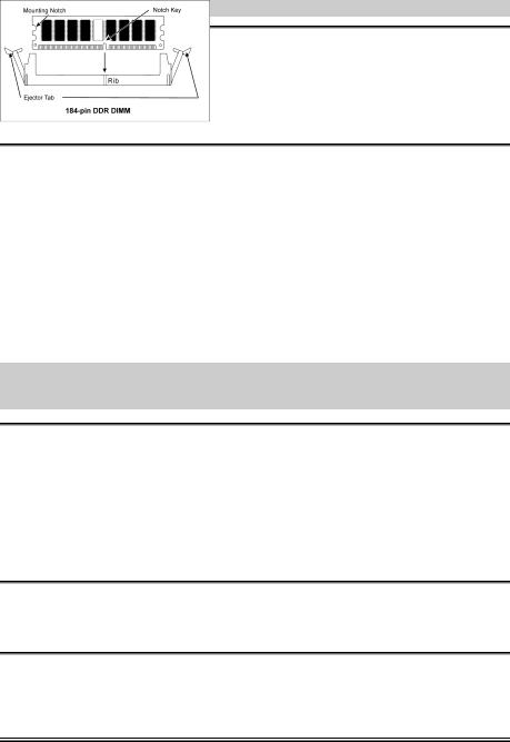
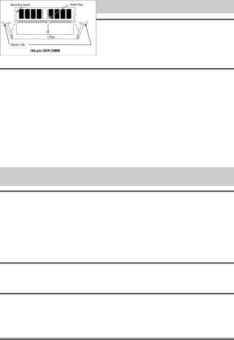
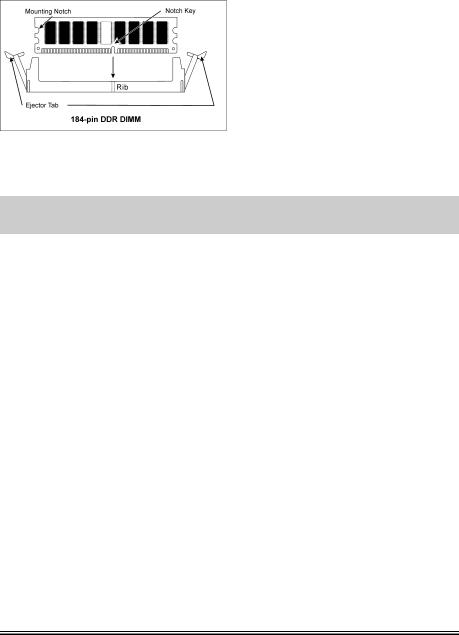
2-3. Install System Memory
This motherboard provides 3 184-pin DDR DIMM sites for memory expansion available from minimum 128MB to maximum 2GB.
Table 2-1. Valid Memory Configurations
Bank |
Memory Module |
Total Memory |
|
|
|
Bank 0, 1 (DIMM1) |
128, 256, 512MB, 1GB |
128MB ~ 1GB |
|
|
|
Bank 2, 3 (DIMM2) |
128, 256, 512MB, 1GB |
128MB ~ 1GB |
|
|
|
Bank 4, 5 (DIMM3) |
128, 256, 512MB, 1GB |
128MB ~ 1GB |
|
|
|
|
Total System Memory |
128MB ~ 2GB |
|
|
|
Table 2-2. AMD Athlon 64 Processor Memory Supporting sets
DRAM |
DIMM1 |
DIMM2 |
DIMM3 |
Memory spec |
|
number |
|||||
|
|
|
|
||
|
|
|
|
|
|
2 |
x8 single rank or x16 |
x8 single rank or x16 |
empty |
DDR400 |
|
|
|
|
|
|
|
2 |
x8 single rank or x16 |
x8 double rank |
empty |
DDR400 |
|
|
|
|
|
|
|
2 |
x8 single rank or x16 |
empty |
x8 single rank or x16 |
DDR400 |
|
|
|
|
|
|
|
2 |
x8 single rank or x16 |
empty |
x8 double rank |
DDR400 |
|
|
|
|
|
|
|
2 |
x8 double rank |
x8 single rank or x16 |
empty |
DDR400 |
|
|
|
|
|
|
|
2 |
x8 double rank |
x8 double rank |
empty |
DDR400 |
|
|
|
|
|
|
|
2 |
x8 double rank |
empty |
x8 single rank or x16 |
DDR400 |
|
|
|
|
|
|
|
2 |
empty |
x8 single rank or x16 |
x8 single rank or x16 |
DDR333 |
|
|
|
|
|
|
|
3 |
x8 double rank |
x8 single rank or x16 |
x8 single rank or x16 |
DDR333 |
|
|
|
|
|
|
|
3 |
x8 single rank or x16 |
x8 single rank or x16 |
x8 single rank or x16 |
DDR333 |
|
|
|
|
|
|
User’s Manual
2-4 |
Chapter 2 |
|
|
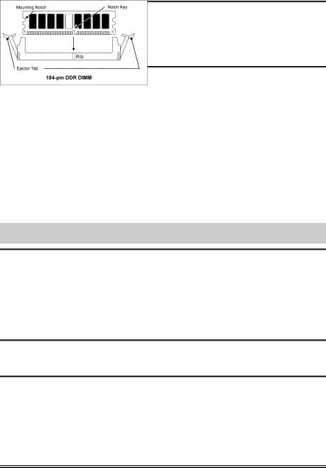
Power off the computer and unplug the AC power cord before installing or removing memory modules.
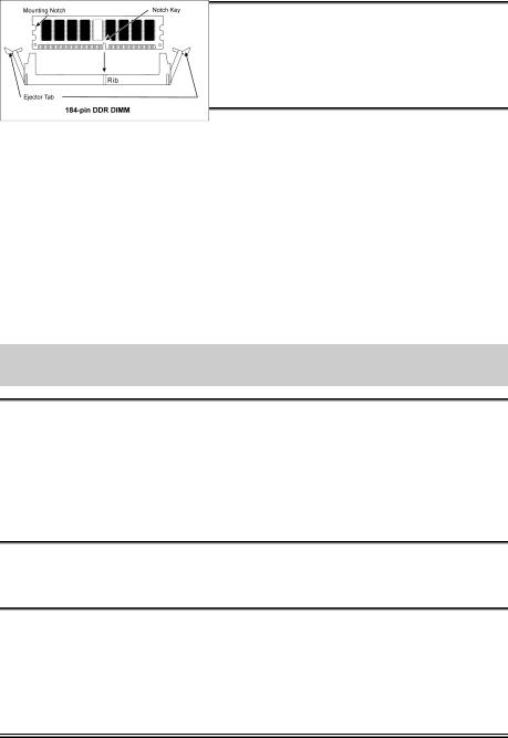
1.Locate the DIMM slot on the board.
2.Hold two edges of the DIMM module carefully, keep away of touching its connectors.
3.Align the notch key on the module with the rib on the slot.
4.Firmly press the module into the slots until the ejector tabs at both sides of the slot automatically snaps into the mounting notch. Do not force the DIMM module in with extra
force as the DIMM module only fit in one direction.
5.To remove the DIMM modules, push the two ejector tabs on the slot outward simultaneously, and then pull out the DIMM module.
ATTENTION: Static electricity can damage the electronic components of the computer or optional boards. Before starting these procedures, ensure that you are discharged of static electricity by touching a grounded metal object briefly.
KV8-MAX3
Hardware Setup |
2-5 |
|
|
2-4. Connectors, Headers and Switches
Here we will show you all of the connectors, headers and switches, and how to connect them. Please read the entire section for necessary information before attempting to finish all the hardware installation inside the computer chassis. A complete enlarged layout diagram is shown in Chapter 1 for all the position of connectors and headers on the board that you may refer to.
WARNING: Always power off the computer and unplug the AC power cord before adding or removing any peripheral or component. Failing to so may cause severe damage to your motherboard and/or peripherals. Plug in the AC power cord only after you have carefully checked everything.
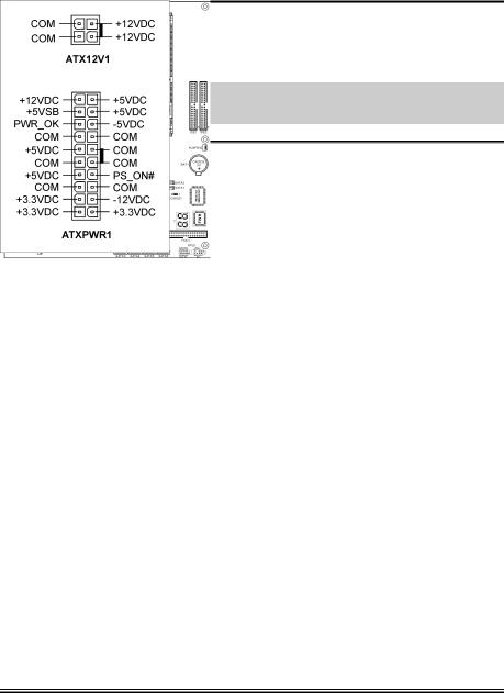
(1). ATX Power Input Connectors
This motherboard provides two power connectors to connect to an ATX12V power supply with 300W, 20A +5VDC, and 720mA +5VSB capacity at least.
User’s Manual
2-6 |
Chapter 2 |
|
|
|
|
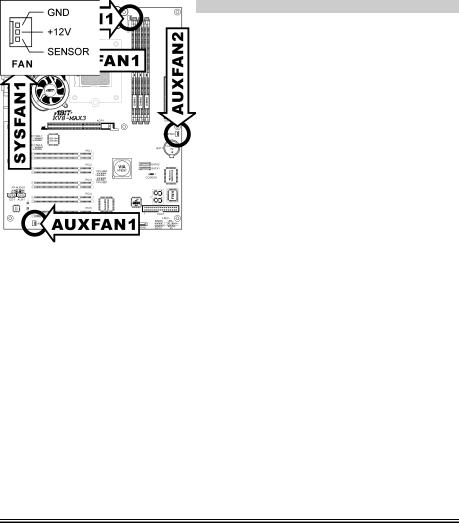
(2). |
FAN Connectors |
These 3-pin connectors each provide power to the cooling fans installed in your system.
•CPUFAN1: CPU Fan
•NBFAN1: Chipset Fan
•SYSFAN1: OTES Fan
•AUXFAN1, AUXFAN2: Auxiliary Fan
WARNING: These fan connectors are not jumpers. DO NOT place jumper caps on these connectors.
KV8-MAX3
Hardware Setup |
2-7 |
|
|
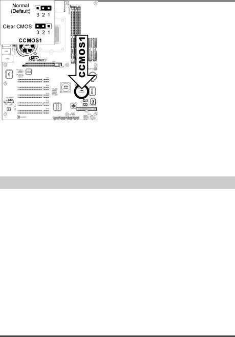
(3). CMOS Memory Clearing Header
This header uses a jumper cap to clear the CMOS memory.
•Pin 1-2 shorted (default): Normal operation.
•Pin 2-3 shorted: Clear CMOS memory.
WARNING: Turn the power off first (including the +5V standby power) before clearing the CMOS memory. Failing to do so may cause your system to work abnormally or malfunction.
User’s Manual
Loading...