

Page 1

Copyright and Warranty Notice
The information in this document is subject to change without notice and does not
represent a commitment on part of the vendor, who assumes no liability or responsibility
for any errors that may appear in this manual.
No warranty or representation, either expressed or implied, is made with respect to the
quality, accuracy or fitness for any particular part of this document. In no event shall the
manufacturer be liable for direct, indirect, special, incidental or consequential damages
arising from any defect or error in this manual or product.
Product names appearing in this manual are for identification purpose only and
trademarks and product names or brand names appearing in this document are the
property of their respective owners.
This document contains materials protected under International Copyright Laws. All
rights reserved. No part of this manual may be reproduced, transmitted or transcribed
without the expressed written permission of the manufacturer and authors of this manual.
If you do not properly set the motherboard settings, causing the motherboard to
malfunction or fail, we cannot guarantee any responsibility.
Page 2

Page 3

SR7-8X Motherboard User’s Manual
Index
CHAPTER 1.
1-1. SR7-8X ㆗文快速安裝指引...............................................................................1-1
1-2. SR7-8X G
1-3. SR7-8X S
1-4. SR7-8X クイックインストールガイド ..........................................................1-13
1-5. G
1-6. К
UIDA ALL’INSTALLAZIONE VELOCE SCHEDA MADRE
РАТКОЕ РУКОВОДСТВО ПО УСТАНОВКЕ
CHAPTER 2.
2-1. F
2-2. S
2-3. I
2-4. L
EATURES OF
PECIFICATIONS
TEM CHECKLIS T
AYOUT DIAGRAM FOR
CHAPTER 3.
3-1. I
3-2. I
3-3. I
3-4. C
NSTALLING THE MOTHERBOARD TO THE CHASSIS
NSTALL PENTIUM®
NSTALLING SYSTEM MEMORY
ONNECTORS
CHAPTER 4.
4-1. SOFT MENU
4-2. S
4-3. A
4-4. A
4-5. P
4-6. PNP/PCI C
4-7. I
4-8. PC H
4-9. S
4-10. L
4-11. L
4-12. L
4-13. S
4-14. E
TANDARD
DVANCED
DVANCED CHIPSET FEATURES SETUP MENU
OWER MANAGEMENT SETUP MENU
NTEGRATED PERIPHERALS
ET PASSWORD
OAD OPTIMIZED DEFAULTS
OAD FAIL SAFE DEFAULTS
OAD ORIGINAL VALUES
AVE
XIT WITHOUT SAVING
SIX LANGUAGES QUICK INSTALLATION GUIDE..... 1-1
UIDE D’INSTALLATION RAPIDE
CHNELLINSTALLATIONSANLEITUNG
INTRODUCTION OF SR7-8X FEATURES....................... 2-1
SR7-8X M
....................................................................................................2-1
INSTALLING THE MOTHERBOARD.............................. 3-1
, H
INTRODUCING THE BIOS ................................................4-1
EALTH STATUS
™
CMOS F
BIOS F
ONFIGURATIONS SETUP MENU
...................................................................................................4-33
& E
XIT SETUP
OTHERBOARD
..................................................................................................2-3
SR7-8X........................................................................... 2-4
4 P
ROCESSOR AND HEATSINK SUPPORTING-BASE
.............................................................................3-4
EADERS AND SWITCHES
III S
....................................................................................4-3
ETUP
EATURES SETUP MENU
EATURES SETUP MENU
.................................................................................4-27
...........................................................................................4-32
..............................................................................4-33
...............................................................................4-34
....................................................................................4-34
...........................................................................................4-34
......................................................................................4-34
.............................................................1-5
......................................................1-9
SR7-8X............................ 1-17
SR7-8X.............................................. 1-21
.................................................................2-1
................................................3-2
...................3-3
...............................................................3-5
.........................................................4-7
.........................................................4-10
.....................................................4-14
..................................................................4-18
...........................................................4-24
APPENDIX A. SIS CHIPSET DRIVERS INSTALLATION FOR WINDOWS®
2000 ........................................................................................ A-1
4200-0306-02 Rev. 1.01
Page 4

APPENDIX B. SIS IDE DRIVERS INSTALLATION FOR WINDOWS® 2000
................................................................................................ B-1
APPENDIX C. AUDIO DRIVERS INSTALLATION FOR WINDOWS® 2000
................................................................................................ C-1
APPENDIX D. LAN DRIVERS INSTALLATION FOR WINDOWS® 2000
................................................................................................ D-1
APPENDIX E. USB 2.0 DRIVERS INSTALLATION FOR WINDOWS® 2000
................................................................................................ E-1
APPENDIX F. INSTALLING THE WINBOND HARDWARE MONITOR
SOFTWARE........................................................................... F-1
APPENDIX G. AMI BIOS UPDATE GUIDE................................................ G-1
APPENDIX H. TROUBLESHOOTING (NEED ASSISTANCE?) ............... H-1
APPENDIX I.
HOW TO GET TECHNICAL SUPPORT .............................. I-1
SR7-8X
Page 5
Six Languages Quick Installation Guide
1-1
Chapter 1. Six Languages Quick Installation Guide
1-1. SR7-8X ㆗文快速安裝指引
®
感謝您購買 ABIT 的主機板,此主機板是設計給英特爾 Pentium
Socket 478 架構的處理器,並支援最高至 2 GB 容量的記憶體(必需是非緩衝式【Unbuffered】PC 2700
的記憶體模組)或是 3 GB(必需是非緩衝式【Unbuffered】PC 1600 或是 PC 2100 的記憶體模組)。
如您要瞭解此主機板更詳細的資訊,請參閱我們的完整版使用手冊,裡面會有詳盡的說明。此快速
安裝手冊是給有經驗的系統組裝者使用,如果這是您第㆒次嘗試來組裝您的電腦系統,我們建議您
先去閱讀完整版的使用手冊,或是詢問技術㆟員來幫助您組裝您的電腦系統。
4 處理器所使用的。支援英特爾
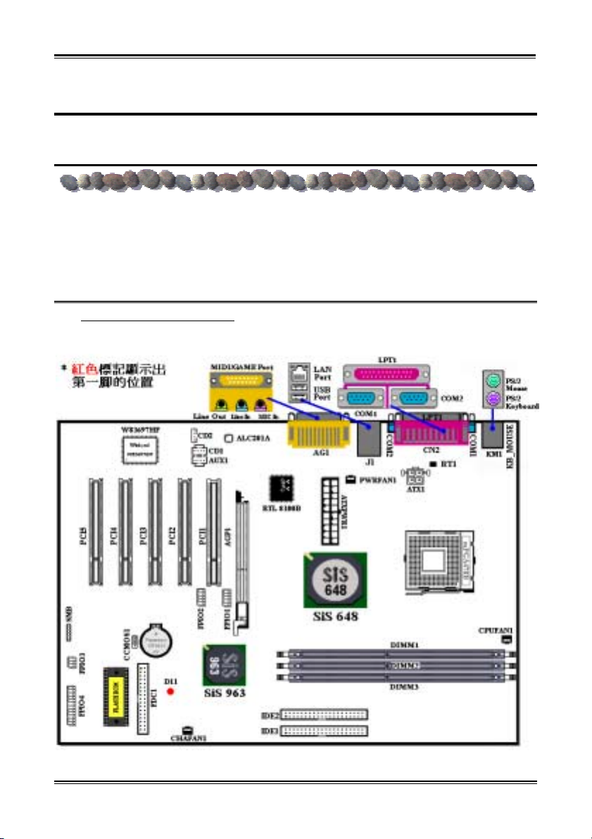
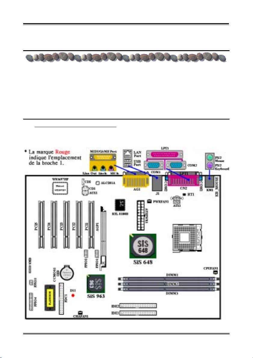
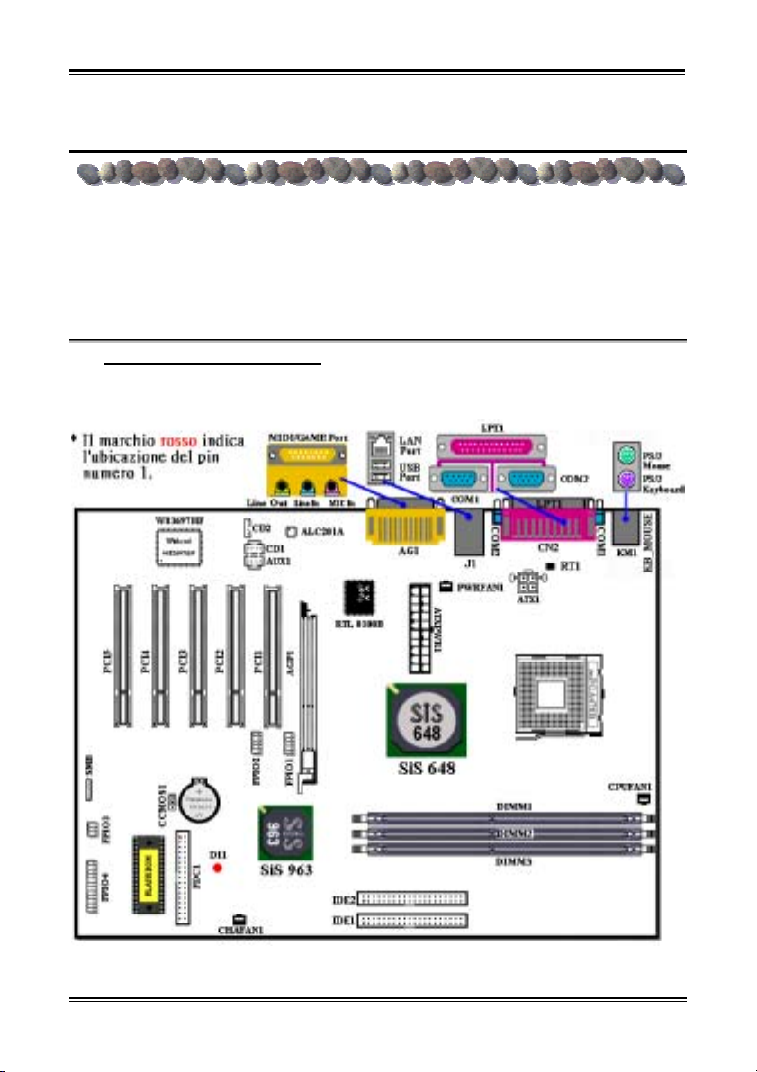
(1). SR7-8X 主機板主要元件配置圖
1 顯示了 SR7-8X 主機板主要元件的配置,此配置圖僅供您參考使用。
圖
圖 1. SR7-8X 主機板主要元件配置圖
User’s Manual
Page 6
Chapter 1
1-2
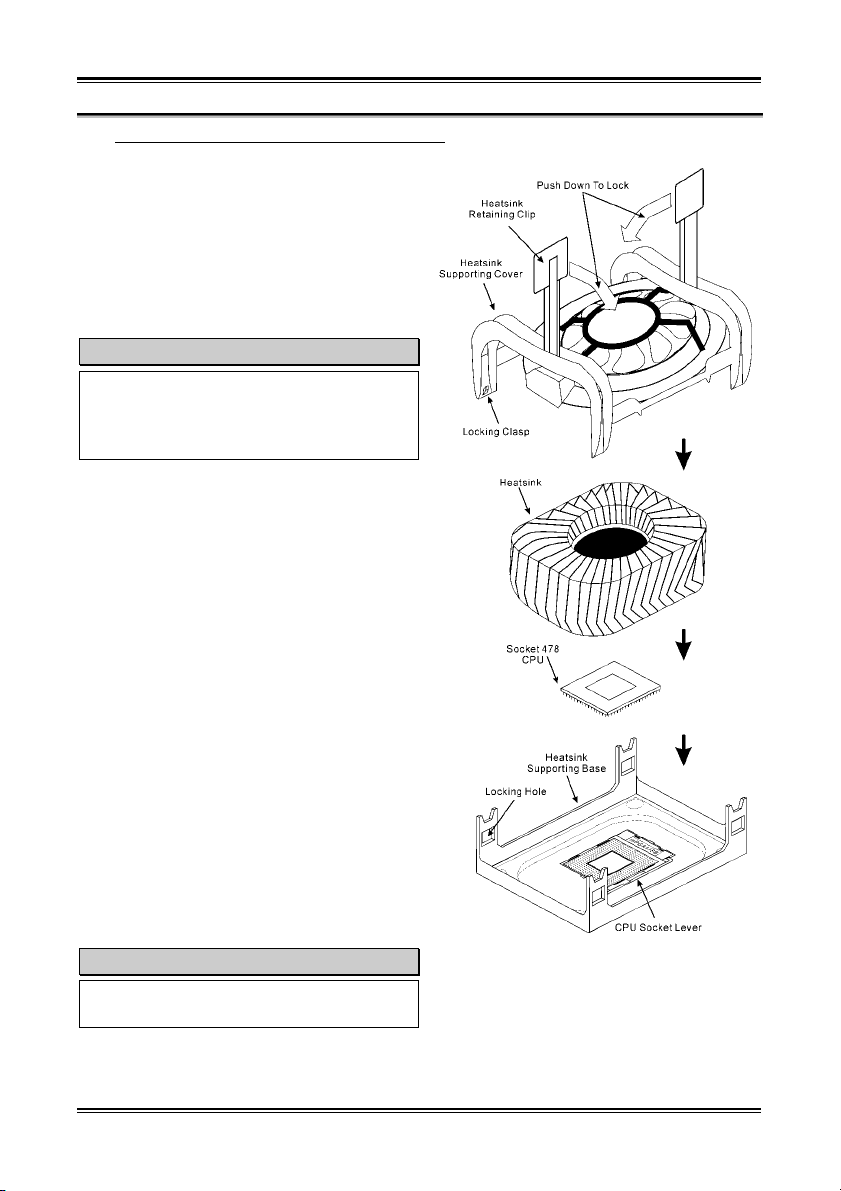
(2). 安裝英特爾 Pentium
®
4 處理器與散熱片固定架
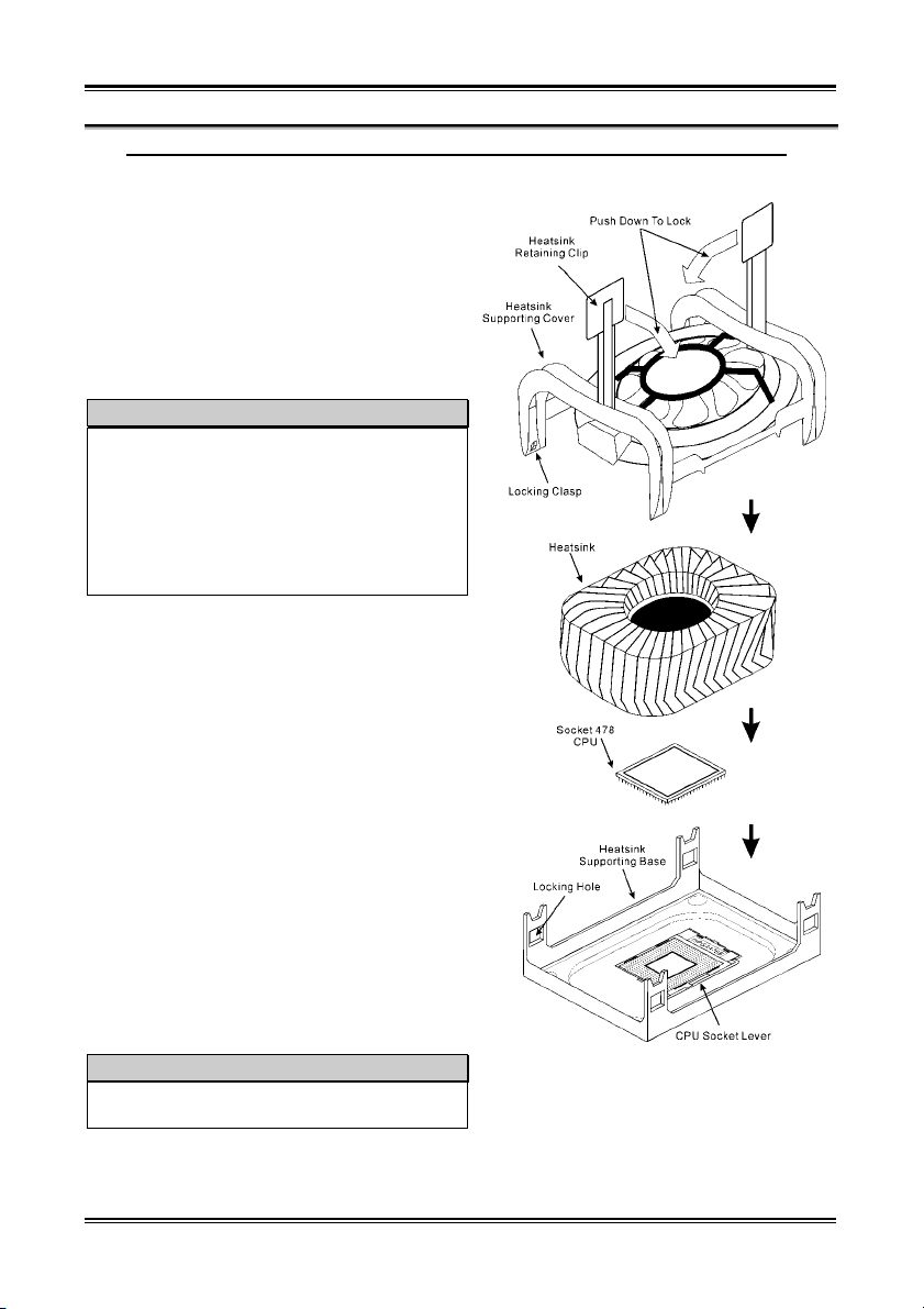
本主機板提供零出力 (Zero Insertion Force, ZIF)
式 Socket 478 插槽,以方便您安裝英特爾 Pentium
4 處理器。您所購買的處理器應該已配備有原廠的
散熱套件。如果沒有的話,請購買專門為英特爾
®
Pentium
4 Socket 478 插槽所設計的散熱片及散熱
風扇。安裝處理器與散熱裝置時請參照圖2-1 所示。
1. 請在主機板㆖面找出 Socket 478 插槽的位置,然
後將散熱片固定架基座固定在主機板㆖。
注意
®
如果您使用專門為英特爾 Pentium
4 處理器
所設計的基座,請注意已經安裝在機箱㆖的金
屬螺栓或墊片。請確定金屬螺栓或墊片沒有接
觸到印刷電路板㆖的線路或是零件。
2. 請將處理器插槽釋放拉桿向插座的外側拉出,然
後將插槽釋放拉桿以 90 度角角度向㆖拉起,然
後請您以正確的方向將處理器插入處理器插
槽。由於您只能朝著㆒個固定的方向插入處理
器,因此如果當您在插入處理器時遇到阻礙的
話,切勿勉強或用力將處理器置入插槽。當處理
器正確㆞置入到處理器插槽之後,請將插槽釋放
拉桿再反方向推到底,並且將插槽釋放拉桿的卡
榫與處理器插槽鎖㆖,如此即完成了處理器的安
裝。
3. 請將散熱片的平坦面向㆘朝著處理器,並沿著散
熱片固定架基座㆕個角落㆖支架的位置將散熱
片置入,直到散熱片完全㆞蓋住處理器為止。
4. 將散熱片的固定架蓋在散熱片㆖。請確定散熱片
固定架㆕個邊角的鎖扣都已到達散熱片固定架
基座的鎖孔位置。
5. 將散熱片固定架兩側的固定夾㆒起往㆘壓,以 將
散熱片固定架㆖的㆕個鎖扣與散熱片固定架基
座㆖的㆕個鎖孔扣㆖。壓住散熱片固定夾時,請
您務必注意固定夾按壓的方向。
6. 現在散熱片固定架及其基座應該已經互相扣
緊,而散熱片也應已固定在散熱片固定架內側。
注意
請您記得要設定正確的處理器外頻和倍頻數
值。
®
圖 2. 安裝英特爾 Pentium
器與散熱片固定架
®
4 Socket 478 處理
SR7-8X
Page 7
Six Languages Quick Installation Guide
1-3
(3). 將主機板安裝到機殼㆖
當您將處理器安裝到主機板㆖之後,您便可以開始將主機板固定到電腦機殼裡去。首先;請您先將
主機板固定到電腦機殼。大多數的電腦機殼底座都有許多的固定孔位,請將主機板㆖的固定孔位與
機殼底座㆖的固定孔位對準。如 果 孔能對準並且有螺絲孔,就表示可使用銅柱來固定主機板。另外;
您可以使用塑膠墊片來讓螺絲與主機板的PCB 表層隔離(絕緣)。
(4). 安裝系統記憶體
本主機板提供㆔組 184 腳的 DDR DIMM 插座可供記憶體擴充,可支援 DDR SDRAM 的最小記憶
體大小為 64 MB,而最大的記憶體大小則為 2 GB
容量的記憶體(必需是非緩衝式【Unbuffered】PC
2700 的記憶體模組)或是 3 GB(必需是非緩衝式
【Unbuffered】PC 1600 或是 PC 2100 的記憶體模
組)。在主機板㆖有㆔個記憶體模組插槽(總共
有六個記憶體模組區塊(Bank))。
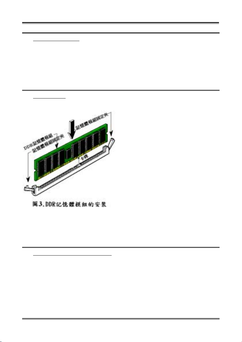
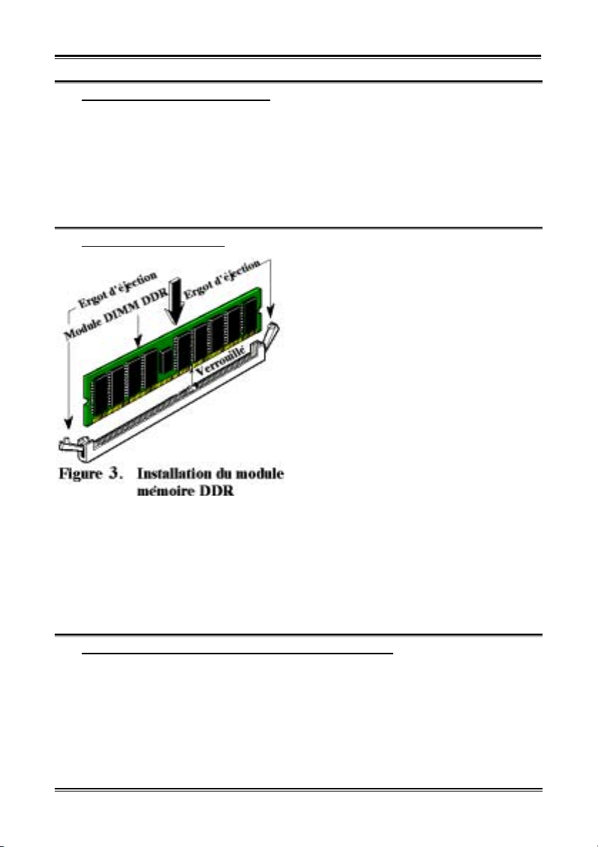
圖3
將DDR DIMM 記憶體模組如
插槽。請注意記憶體模組的楔子是如何對應到
DIMM 插槽㆖的卡榫之㆖。
所示,插 入 DIMM
此種設計可確保 DDR
DIMM 記憶體模組僅能由㆒個方向插到 DIMM 插
槽之㆖
。當您將 DDR DIMM 記憶體模組完全插
入 DIMM 插槽時,模組退出 (固定) 夾應該會將
DDR DIMM 記憶體模組自兩側卡緊並緊緊㆞固定
住記憶體模組。
我們建議您將記憶體模組依照DIMM1 至 DIMM3
的順序妥善㆞安裝於記憶體插槽。
最後;您必需將所有必需的裝置纜線連接到主機板㆖相關的連接頭或是連接器㆖面,以完成您系統
的硬體安裝動作。
(5). 連接器、連接頭以及其它附加卡的安裝
在任何㆒部電腦機殼的裡面,都必需連接㆒些纜線與插頭。這 些纜線與插頭通常都是㆒對㆒的連接
至主機板的連接埠㆖,您必需注意任何㆒條纜線的連接方向。如果可能的話,請㆒併注意連接埠第
㆒根針腳的位置。您將會安裝㆒些特殊功能的附加卡到主機板㆖面,像是 SCSI 卡或是 AGP 顯示
卡等等。當您將它們安裝到主機板㆖適當的插槽之後,請以螺絲將這些附加卡與機殼背板牢牢㆞固
定好,避免有鬆動的情況發生。如您想要瞭解相關且更為詳細的資訊,請參閱我們的完整版使用手
冊,裡面會有詳盡的說明。
User’s Manual
Page 8
Chapter 1
1-4
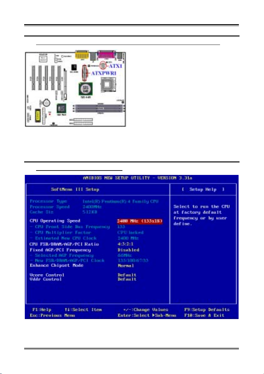
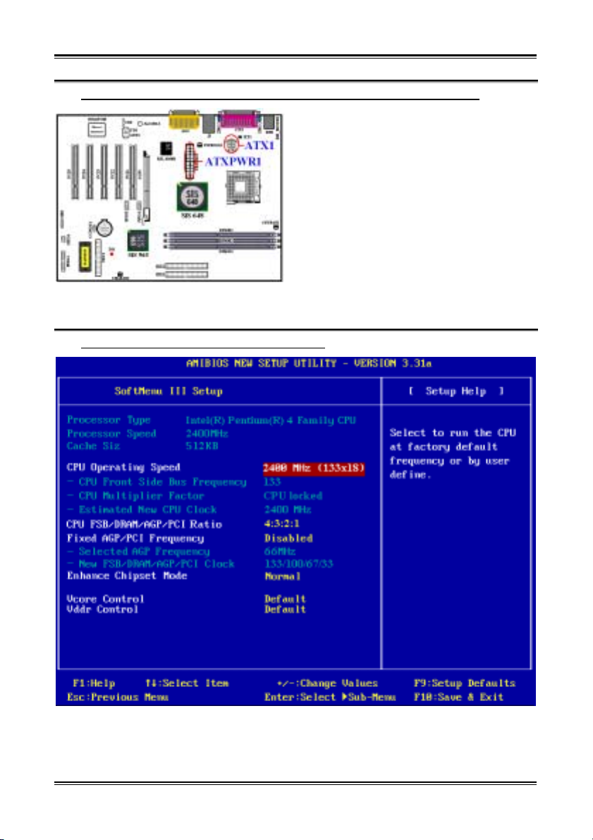
(6). 將電源供應器的電源線連接頭與主機板㆖的 ATX1 以及 ATXPWR1 連接頭連接起來
SR7-8X 所需要的電源要求與㆒般的處理器不太
相同(它需要使用設計給 Pentium
®
4 處理器所使
用的電源供應器),它有全新設計的 ATX1 之+12V
直流電源、具備至少 300W 功率,以及它對重量
型負載系統至少也可以提供+5V 直流電源之電流
20A(安培)以㆖的供電容量。而對支援㆒些其
他的特殊功能方面,它至少也可提供+5VSB 電壓
部份至少 720mA(毫安)的電流容量。
®
請自您的 Pentium
4 專用 ATX 電源供應器㆖將
ATXPWR1 以及 ATX12V1 的電源纜線插頭插到
主機板㆖標示為 ATXPWR1 以及 ATX1 的連接頭
㆖去。請先檢查電源纜線插頭的方向正確之後,
再牢牢㆞把插頭插到連接頭裡固定。
注意:請注意接腳的位置及方向。
™
(7). 處理器參數的設定 [SOFT MENU
III]
當您將所有的硬體安裝完畢以後, 就可以開啟電腦的電源並進入 BIOS 的選項。請選擇「SoftMenu
III Setup」的項目以進行處理器參數的設定。如您想要瞭解相關且更為詳細的資訊,請參閱我們的
完整版使用手冊,裡面會有詳盡的說明。
SR7-8X
Page 9
Six Languages Quick Installation Guide
1-5
1-2. SR7-8X Guide d’Installation Rapide
Merci pour votre achat de cette carte mère ABIT. Cette carte mère est conçue pour les processeurs Intel
®
Pentium
4. Elle accepte les architectures Socket 478 Intel®, avec jusqu'à 2 GB (unbuffered, PC 2700)
ou 3 GB (unbuffered, PC 1600/PC 2100) de mémoire SDRAM DDR.
Pour des informations relatives à cette carte mère plus détaillées, veuillez vous référer à notre version
complète du manuel utilisateur. Ce guide d’installation rapide est créé pour les assembleurs système
expérimentés. S’il s’agit de votre premier essai pour installer un ordinateur, nous vous suggérons de lire
d’abord le manuel en version complète ou de demander l’aide d’un technicien pour vous aider à
configurer le système ordinateur.
®
(1). Emplacement de la Carte Mère SR7-8X
La Figure 1 montre le schéma d’implantation de la SR7-8X. Nous montrons tous les composants
principaux dans ce schéma pour votre référence.
Figure 1. Schéma d'implantation de la SR7-8X
User’s Manual
Page 10
Chapter 1
1-6
®
(2). Installation du processeur Pentium
4 et de la base de support du dissipateur de chaleur
Cette carte mère fournit une socket ZIF (force
d'insertion nulle) 478 permettant d’installer le
processeur Intel
®
Pentium® 4. Le processeur que vous
avez acheté doit disposer d’un dissipateur de chaleur
et d'un ventilateur de refroidissement. Si ça n’est pas
le cas, veuillez en acquérir un spécialement conçu
pour le Pentium
®
4 socket 478. Veuillez vous reporter
à l’illustration 2 pour installer le processeur.
1. Localiser la socket 478. Serrer la base de support
du dissipateur de chaleur sur la carte mère.
Attention
Si vous utilisez un châssis spécialement conçu
pour le Pentium® 4, veuillez faire attention à
l’emplacement des clous ou des espaceurs
métalliques s’ils sont déjà installés sur le châssis.
Veuillez vous assurer que les clous ou les
espaceurs métalliques n’entrent pas en contact
avec les fils du circuit imprimé ou les pièces sur
le circuit imprimé.
2. Tirer sur le levier de la socket du processeur vers le
côté afin de l’éloigner de la socket puis vers le haut
sur 90 degrés. Insérer le processeur dans le bon
sens. Ne pas forcer pour insérer le processeur ; il
ne peut être installé que dans un sens. Fermer le
levier de la socket tout en maintenant le processeur
vers le bas.
3. Installer les faces du dissipateur de chaleur sur le
processeur jusqu’à ce qu’elles couvrent
entièrement le processeur.
4. Installer le couvercle de support du dissipateur de
chaleur sur ce dernier. S’assurer que les quatre
fermoirs situés de chaque côté du couvercle de
support atteignent les orifices de verrouillage.
5. Appuyer sur l’étrier de retenue situé des deux côtés
du couvercle de support afin de le verrouiller sur la
base de support. Vérifier le sens de poussée de
l’étrier de retenue.
6. Le couvercle et la base de support du dissipateur
de chaleur doivent désormais s’enclencher
fermement avec la partie intérieure du dissipateur
de chaleur.
Attention
Ne pas oublier de régler le multiple et la
fréquence de bus de votre processeur.
Illustration 2. Installation du processeur P4
Socket 478 et de son dissipateur de chaleur
dans sa base de support.
SR7-8X
Page 11
Six Languages Quick Installation Guide
1-7
(3). Installer la Carte Mère dans le Châssis
Une fois que vous aurez installé le processeur sur la carte mère, vous pourrez commencer à fixer la carte
mère sur le châssis. Tout d’abord, vous avez besoin de fixer la carte mère sur le châssis. La plupart des
châssis d’ordinateur possèdent une base sur laquelle il y a nombreux trous de montage permettant à la
carte mère d’être fixée fermement, et en même temps d’éviter les court-circuits. Utilisez les talons ou les
entretoises fixés sur le châssis pour fixer la carte mère.
(4). Installer la Mémoire Système
Cette carte mère dispose de trois emplacements
DIMM DDR 184-broches pour les extensions
mémoire. La mémoire minimum est de 64 MB et la
mémoire maximum est de 2 GB (unbuffered, PC
2700) ou 3 GB (unbuffered, PC 1600/PC 2100) de
SDRAM DDR. Il y a trois emplacements pour les
modules mémoire sur la carte (pour un total de six
banques).
Insérez le module DDR DIMM dans l’emplacement
d’extension comme illustré dans le schéma. Notez
comment le module est verrouillé dans
l’emplacement. Vous pouvez vous référer à la
Figure 3 pour les détails. Ceci assure qu’il n’y
qu’une manière d’insérer le module DDR DIMM.
Pressez fermement le module DDR DIMM dans
l’emplacement DDR DIMM; assurez-vous que le
module est installé complètement dans
l’emplacement DDR DIMM.
Pour ces modules, nous vous suggérons de remplir les emplacements de DIMM1 à DIMM3 en respectant
l'ordre.
Ensuite, vous aurez à connecter les câbles de tous les périphériques nécessaires dans les socles de
connexion et connecteurs correspondants se trouvant sur la carte mère pour terminer l’installation
matérielle de votre système.
(5). Connecteurs, Socles de connexion, Interrupteurs et Adaptateurs
A l’intérieur du boîtier de n’importe quel ordinateur il y a plusieurs câbles et prises qui doivent être
connectés. Ces câbles et prises sont habituellement connectés les uns après les autres aux connecteurs
situés sur la carte mère. Vous avez besoin de faire attention au sens de connexion des câbles et, s’il y a
lieu, remarquez la position de la première broche du connecteur. Vous installerez certains adaptateurs
pour des besoins spéciaux, tels adaptateurs SCSI, adaptateurs AGP, etc. Lorsque vous les installez dans
les emplacements situés sur la carte mère, veuillez les fixer sur le panneau arrière du châssis à l'aide des
vis. Pour les informations détaillées, veuillez vous référer au manuel utilisateur en version complète.
User’s Manual
Page 12
Chapter 1
1-8
(6). Brancher les connecteurs d'alimentation dans les connecteurs ATX1 et ATXPWR1
La SR7-8X nécessite une alimentation différente des
alimentations habituelles (Source d’alimentation
conçue pour une utilisation avec les processeurs
®
Pentium
4). Il s’agit d’une source d’alimentation de
nouvelle conception ATX1 +12VDC avec une
puissance de 300W, et une capacité de 20A +5VDC
au minimum pour les systèmes fortement chargés et
720mA +5VSB au moins pour supporter certaines
fonctions spécifiques.
Fixez le connecteur de la source d’alimentation sur
les connecteurs ATXPWR1 et ATX12V1.
Rappelez-vous que vous devez bien pousser le
connecteur de votre alimentation sur les connecteurs
ATXPWR1 et ATX1, pour vous assurer une bonne connexion.
Remarque: Faites attention à la position des broches et à l'orientation.
(7). Configuration du Processeur [SOFT MENU™ III]
Une fois le matériel installé complètement, démarrez l'ordinateur et allez sur l'item「SoftMenu III Setup」
dans le BIOS pour configurer les paramètres du processeur. Pour les informations détaillées, veuillez
vous référer à la version complète du manuel utilisateur.
SR7-8X
Page 13
Six Languages Quick Installation Guide
1-9
1-3. SR7-8X Schnellinstallationsanleitung
Vielen Dank für Ihren Kauf dieses ABIT-Motherboards. Dieses Motherboard wurde für Intel
4-Prozessoren entworfen. Es unterstützt die Intel
®
Socket 478-Architekturen mit bis zu 2 GB (Unbuffered,
®
Pentium®
PC 2700) oder 3 GB (Unbuffered, PC 1600/PC 2100) DDR SDRAM-Arbeitsspeicher.
Beziehen Sie sich bitte für detaillierte Informationen über diese Hauptplatine auf die vollständige Version
des Benutzerbuchs. Diese Schnellinstallationsanleitung ist für erfahrene Systemaufbauer gedacht. Ist es
Ihr erster Versuch ein Computersystem aufzubauen, dann empfehlen wir Ihnen zuerst das vollständige
Benutzerhandbuch zu lesen oder einen Techniker zum Aufbauen des Systems zu Hilfe zu holen.
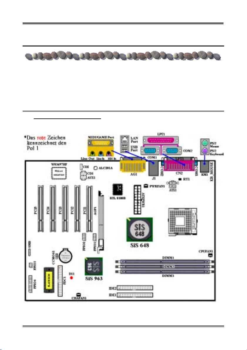
(1). Layout der SR7-8X Hauptplatine
Die Abb. 1 stellt das SR7-8X Layout dar. Alle Hauptkomponenten werden in dieser Abbildung angezeigt.
Abb 1. SR7-8X Layout
User’s Manual
Page 14
Chapter 1
1-10
®
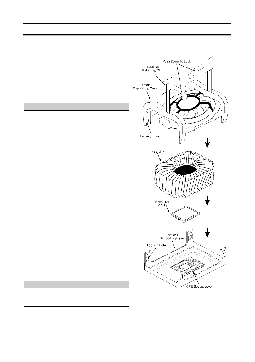
(2). Installation von Intel
Dieses Motherboard bietet einen ZIF (Zero Insertion
Force) Sockel 478 zur Installation eines Intel
®
Pentium
4 Prozessors. Ihr Prozessor sollte mit einem
Pentium® 4-Prozessor und Kühlblech mit Basis
®
Kühlblech/Lüftersatz geliefert werden. Wenn dies
nicht der Fall ist, kaufen Sie einen solchen Satz, der
speziell für Pentium
®
4 Sockel 478 entwickelt wurde.
Bitte schauen Sie sich Abb. 2 zur Installation des
Prozessor an.
1. Finden Sie den Sockel 478. Befestigen Sie das
Kühlblech mit der Basis auf dem Motherboard.
Achtung
Wenn Sie ein speziell für den Pentium® 4
entwickeltes Chassis verwenden, achten Sie bitte
auf die Lage der Metallstifte oder Abstandhalter,
wenn diese schon auf dem Chassis installiert sind.
Passen Sie auf, dass die Metallstifte bzw.
Abstandhalter nicht in Kontakt mit den
gedruckten Schaltkreisen oder Teilen auf dem
PC-Board kommen.
2. Ziehen Sie den Hebel des Prozessorsockels
seitwärts vom Sockel und dann im 90 Grad-Winkel
nach oben. Setzen Sie den Prozessor mit der
korrekten Ausrichtung hinein. Wenden Sie keine
Gewalt beim Einsetzen des Prozessors ein; er passt
nur in eine Ausrichtung hinein. Drücken Sie den
Sockelhebel wieder herunter, während Sie den
Prozessor heruntergedrückt halten.
3. Setzen Sie das Kühlblech mit der Oberseite nach
unten auf den Prozessor, bis es den Prozessor
völlig abdeckt.
4. Setzen Sie die Kühlblechabdeckung auf das
Kühlblech. Vergewissern Sie sich, dass alle vier
Halteklammern zu jeder Seite der Abdeckung in
die Haltelöcher greifen.
5. Drücken Sie den Halteclip auf beiden Seiten der
Abdeckung herunter, bis er in die Basis
einschnappt. Achten Sie beim Herunterdrücken des
Clips auf die Richtung.
6. Kühlblechabdeckung und Basis sollten nun fest
miteinander verriegelt sein und das Kühlblech sich
in ihrem Innern befinden.
Achtung
Vergessen Sie nicht, die korrekte Busfrequenz und
den korrekten Multiplikator für Ihren Prozessor
einzustellen.
Abb. 2. Installation von Intel
4-Prozessor und Kühlblech mit Basis.
®
Pentium®
SR7-8X
Page 15
Six Languages Quick Installation Guide
1-11
(3). Installieren der Hauptplatine im Gehäuse
Nach der Installation des Prozessors können Sie anfangen die Hauptplatine im Computergehäuse zu
befestigen. Die meisten Gehäuse haben eine Bodenplatte, auf der sich eine Reihe von Befestigungslöcher
befinden, mit deren Hilfe Sie die Hauptplatine sicher verankern können und zugleich Kurzschlüsse
verhindern. Verwenden Sie entweder die Dübeln oder die Abstandhalter, um die Hauptplatine auf der
Bodenplatte des Gehäuses zu befestigen.
(4). Installieren des Arbeitsspeichers
Das Motherboard verfügt über drei 184-polige DDR
DIMM-Steckplätze für Speichererweiterung. Die
minimale Speichermenge ist 64 MB, die maximale
Speichermenge ist 2 GB (Unbuffered, PC 2700)
oder 3 GB (Unbuffered, PC 1600/PC 2100) DDR
SDRAM. Das Board bietet drei
Speichermodulsteckplätze (für insgesamt sechs
Bänke).
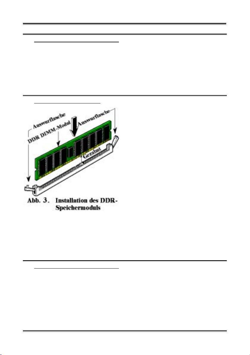
Stecken Sie das DDR DIMM-Modul in den
Speichersteckplatz ein, wie in der Abbildung
dargestellt. Achten Sie darauf, wie die Kerbe des
Moduls in den Steckplatz passt. Schauen Sie sich
bitte Abb. 5 an. So ist sichergestellt, dass das DDR
DIMM-Modul nur in eine Richtung in den
Steckplatz eingesteckt werden kann. Drücken Sie
das DDR DIMM-Modul fest in den DDR
DIMM-Steckplatz, bis es komplett und fest darin
sitzt.
Wir empfehlen Ihnen, diese Module in der
Reihenfolge von DIMM1 nach DIMM3 zu bestücken.
Danach müssen Sie alle nötigen Gerätekabel mit den entsprechenden Sockeln und Anschlüssen auf der
Hauptplatine verbinden, um die Hardwareinstallation Ihres Systems zu vervollständigen.
(5). Anschlüsse, Sockel, Schalter und Adapter
Im Inneren des Gehäuses findet man in jedem Computer viele Kabel und Stecker, die angeschlossen
werden müssen. Diese Kabel und Stecker werden normalerweise einzeln mit den Anschlüssen auf der
Hauptplatine verbunden. Sie müssen genau auf die Anschlussorientierung der Kabel achten und, wenn
vorhanden, sich die Position des ersten Pols des Anschlusses merken. Wenn Sie Adapter wie z.B.
SCSI-Adapter, AGP-Adapter usw. installieren, befestigen Sie bitte die Adapter immer mit Hilfe der
Schrauben auf die Rückseite des Computergehäuses.
Für detaillierte Informationen beziehen Sie sich bitte auf das vollständige Benutzerhandbuch.
User’s Manual
Page 16
Chapter 1
1-12
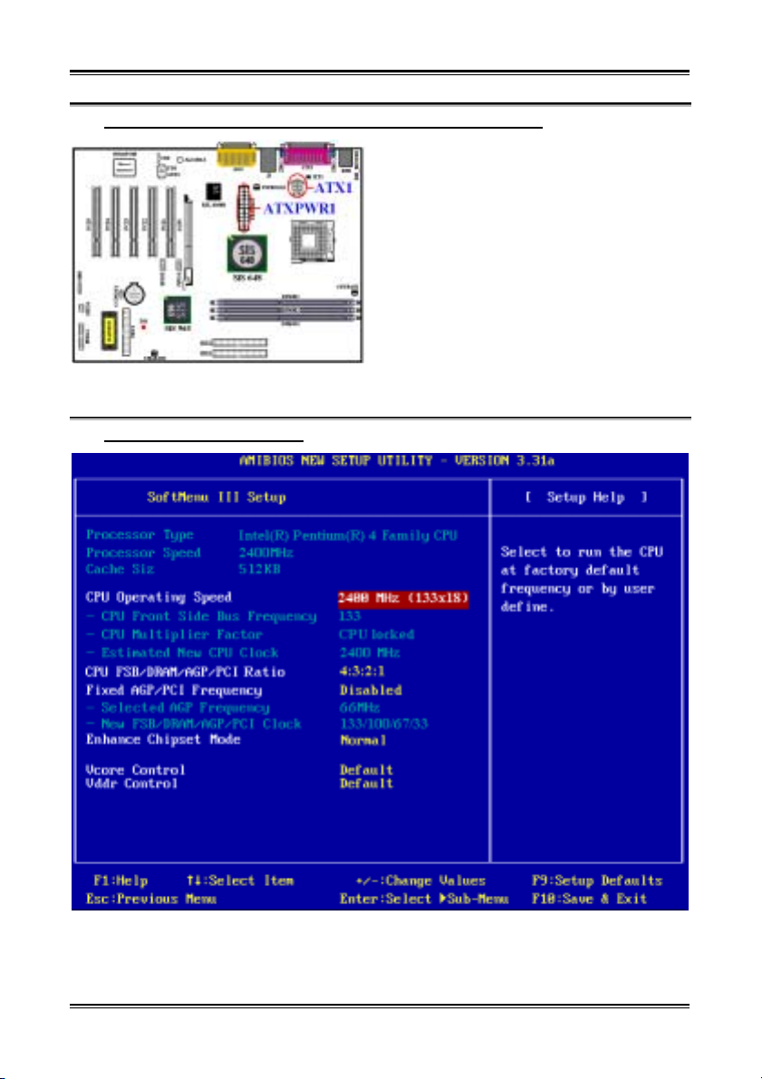
(6). Verbinden der Netzstecker mit dem ATX1- und ATXPWR1-Anschluss
Die SR7-8X benötigt eine von der üblichen
Stromversorung (für Pentium
abweichende Stromversogung. Dies ist eine neu
entworfene ATX1 +12VDC Stromversorgung mit
mindesten 300W, 20A +5VDC für schwer belastete
Systeme und mindesten 720mA +5VSB zur
Unterstützung besonderer Funktionen.
Verbinden Sie die Netzstecker mit dem ATXPWR1und ATX12V1-Anschluss. Stecken Sie unbedingt
die ATX-Netzstecker komplett in den ATXPWR11und ATX1-Anschluss ein, um eine gute Verbindung
sicherzustellen.
Hinweis: Achten Sie auf die richtige Ausrichtung und Position der Pole.
™
(7). CPU-Setup [SOFT MENU
III]
®
4-Prozessore)
Schalten Sie nach der vervollständigten Hardwareinstallation den Computer ein und gehen zur Option
「SoftMenu III Setup」im BIOS, um die Prozessorparameter einzustellen. Für detaillierte Informationen
beziehen Sie sich bitte auf das vollständige Benutzerhandbuch.
SR7-8X
Page 17
Six Languages Quick Installation Guide
1-13
1-4. SR7-8X クイックインストールガイド
ABIT マザーボードをお買い上げいただき、ありがとうございます。このマザーボードは Intel
®
Pentium
し、最高 2 GB (バッファなし、PC 2700)または 3 GB ( バッファなし、PC 1600/PC 2100)の DDR SDRAM
メモリを搭載しています。
このマザーボードの詳細については、ユーザーズマニュアルの完全版を参照してください。この
クイックインストールガイドは、経験あるシステム構築者向けに書かれました。今回始めてコン
ピュータシステムをセットアップする方は、まず完全版のマニュアルをお読みになるか、専門技
術者に連絡してコンピュータシステムのセットアップを行うようお勧めします。レバー
4 プロセッサ用に設計されたものです。Intel® Socket 478 アーキテクチャをサポート
®
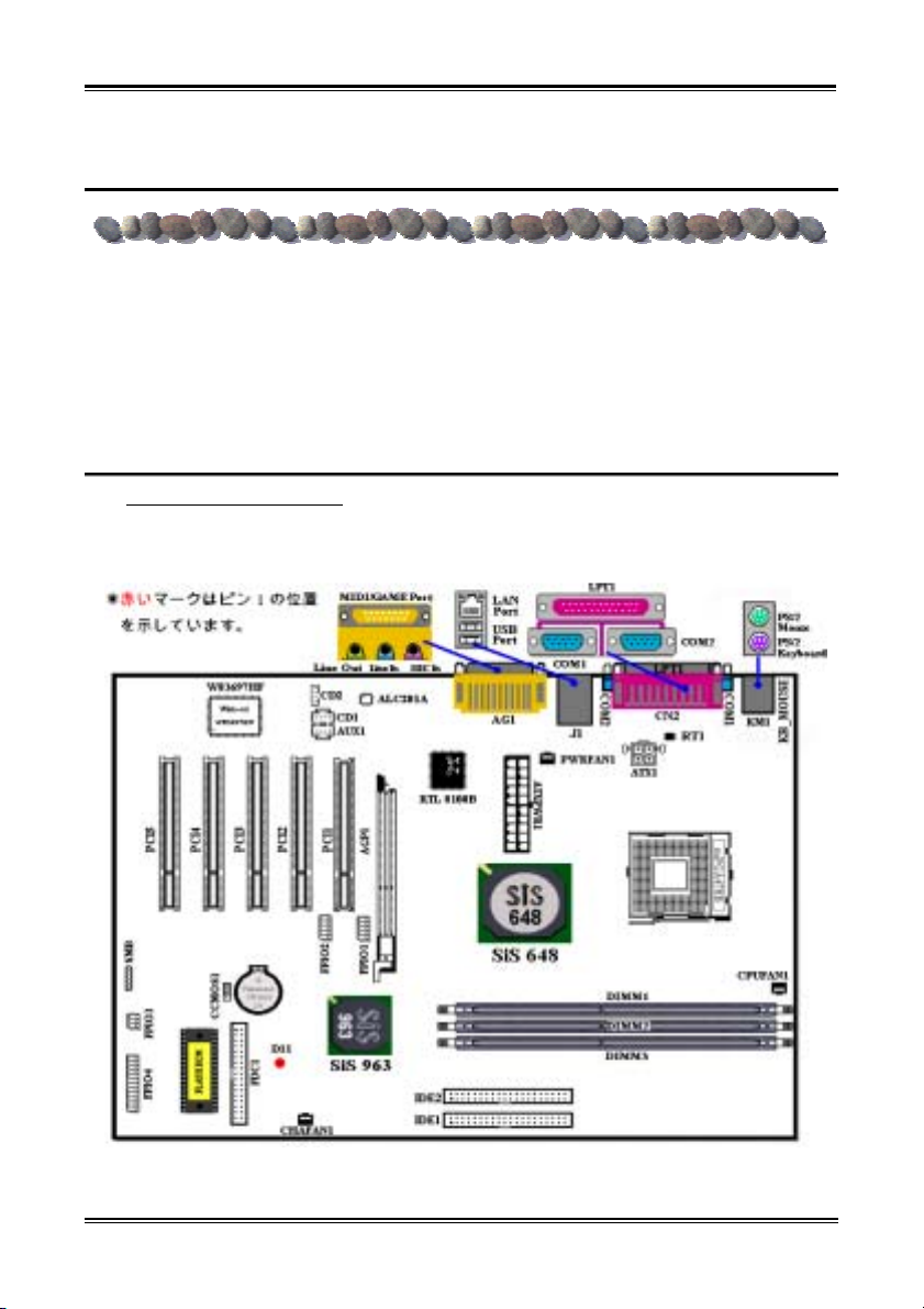
(1). SR7-8X マザーボードの配置
図 1
では、SR7-8X のレイアウト図を示しています。参考のために、この図ですべての主要なコ
ンポーネントを表示します。
図 1. SR7-8X レイアウト図
User’s Manual
Page 18
Chapter 1
1-14
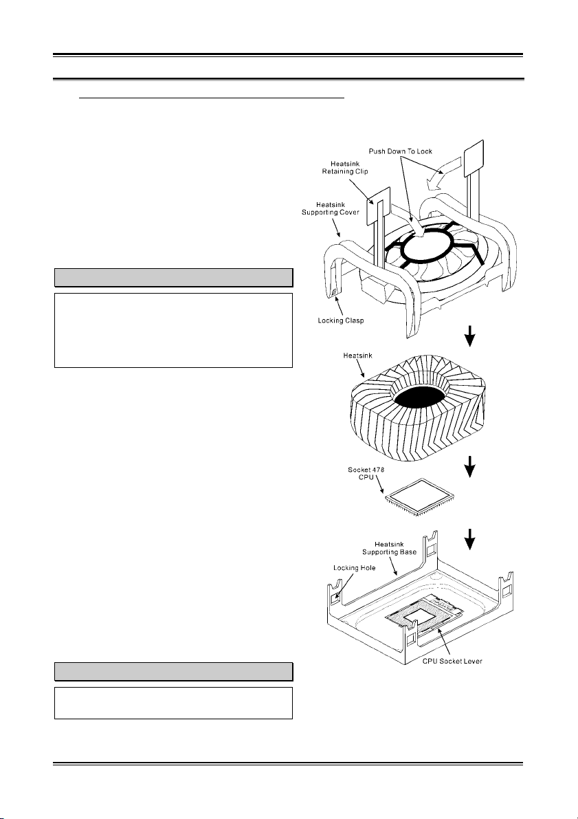
(2). Pentium
®
4 プロセッサおよびヒートシンクの取り付け
このマザーボードには Intel® Pentium® 4 プロセ
ッサを取り付けるための ZIF(Zero Insertion
Force)Socket 478 が備えられています。購入し
たプロセッサには通常、ヒートシンクと冷却ファ
ンのキットが付属しています。付属していない場
合は、Pentium
®
4 Socket 478 用のキットを別に
お求めください。図 2 を参照して、プロセッサを
取り付けてください。
1. Socket 478 の位置を確認し、マザーボードに
ヒートシンクの台座を取り付けます。
注意
Pentium® 4 用のシャーシを使用しており、金
属製のスタッドまたはスペーサをシャーシに
取り付ける場合は、スタッドまたはスペーサ
が基板の回線や一部に接触することがないよ
う注意してください。
2. ソケットレバーをソケットから外して、90°
の角度まで引き上げます。プロセッサを正しい
向きに挿入してください。プロセッサは正しい
向きでしか固定できないので、無理に挿入しな
いでください。プロセッサが挿入できたら、ソ
ケットレバーを元の位置に戻します。
3. プロセッサを完全にカバーするようにヒート
シンクを取り付けてください。
4. ヒートシンクのサポートカバーをヒートシン
クに取り付けます。サポートカバーの 4 つの留
め金が台座の差し込み口の位置に対応してい
るかどうか確認してください。
5. サポートカバー両側のホルダークリップを持
って、サポートカバーを台座に固定します。ク
リップを差し込む方向に注意してください。
6. ヒートシンクのサポートカバーと台座で、ヒ
ートシンクがしっかりと固定されているかど
うか確認してください。
注意
プロセッサのバス周波数と倍数を正しく設定
するのを忘れないでください。
図 2. P4 Socket 478 プロセッサとヒートシ
ンクの取り付け
SR7-8X
Page 19
Six Languages Quick Installation Guide
1-15
(3). マザーボードをシャーシに取り付ける
マザーボードにプロセッサを取り付けた後、シャーシにマザーボードを固定することができるよ
うになります。まず、シャーシにマザーボードを固定する必要があります。ほとんどのコンピュ
ータシャーシには、多くの取り付け穴の付いた台が付属しており、それを使用することでマザー
ボードをしっかり取り付けたり、同時にショートを避けることができます。シャーシに付属する
飾りボタンかスペーサーを使用してマザーボードを固定します。
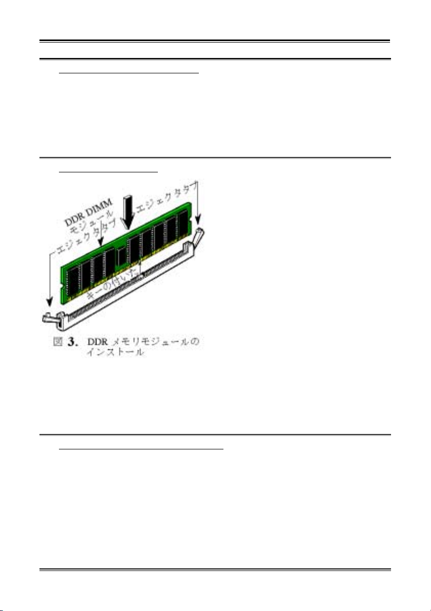
(4). システムメモリの取り付け
このマザーボードは、3 つの 184 ピン DDR DIMM ス
ロットメモリ拡張機能を提供しています。最小
メモリは 64 MB で、最大メモリは 2 GB (バッフ
ァなし、PC 2700)または 3 GB (バッファなし、
PC 1600/PC 2100) DDR SDRAM です。ボードには
3 つのメモリモジュールソケットが搭載されて
います(合計 6 バンク)。
DDR DIMM を図に示すように拡張スロットに差し
込みます。モジュールがソケットにどのように
固定されているか注意してください。詳細につ
図 3
いては、
を参照してください。
これにより、
DDR DIMM モジュールに差し込む方法が 1 つしか
ないことを確認できます。
を DDR DIMM ソケットにしっかりと押し込み、モ
ジュールが DDR DIMM ソケットに完全に差し込ま
れていることを確認します。
これらのモジュールに関しては、DIMM1 から
DIMM3 まで順に差し込むようお勧めします。
次に、すべての必要なデバイスケーブルをマザーボードの関連ヘッダとコネクタに接続して、シ
ステムのハードウェア取付けを終了する必要があります。
DDR DIMM モジュール
(5). コネクタ、ヘッダ、スイッチおよびアダプタ
コンピュータのケース内部には、複数のケーブルやプラグを接続できます。これらのケーブルや
プラグは、通常マザーボードにあるコネクタに 1 つずつ接続されます。ケーブルの接続方向には
十分な注意を払い、また必要に応じ、コネクタの第 1 ピンの位置にも注目する必要があります。
SCSI アダプタ、AGP アダプタのような特殊なニーズ向けには、それに対応したアダプタを取り付
けてください。アダプタをマザーボードのスロットに取り付けたら、ネジでシャーシの背面パネ
ルに固定してください。
詳細については、ユーザーズマニュアルの完全版を参照してください。
User’s Manual
Page 20
Chapter 1
1-16
(6). 電源コネクタを ATX1 および ATXPWR1 コネクタに差し込む
SR7-8X は標準とは異なる電源装置を必要としま
す(Pentium
®
4 プロセッサを使用するために設
計された電源装置)。これは新しく設計された
ATX1 +12VDC 電源で、重い負荷のかかったシス
テム用に少なくとも 300W、20A +5VDC 容量、お
よび一部の特殊機能をサポートするために少な
くとも 720mA +5VSB 容量を持っています。
電源装置から出ているコネクタを ATXPWR1 と
ATX12V1 コネクタに接続します。ATX 電源装置か
ら出ているコネクタを ATXPWR1 や ATX1 コネクタ
を持つ端にしっかり押し込み、接続が完全であ
ることを確認する必要があることを忘れないで
ください。
注意: ピンの位置と方向をよく確認してください。
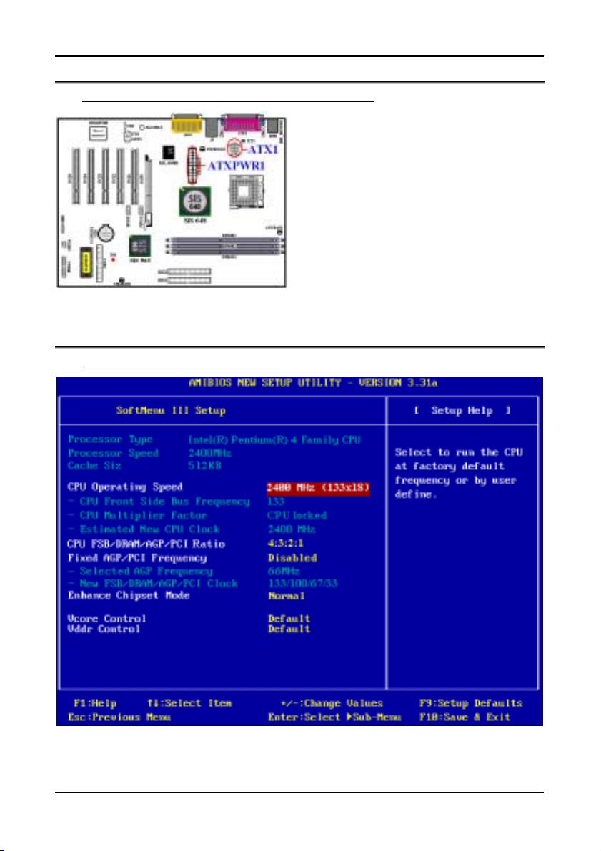
(7). CPU のセットアップ [SOFT MENU™ III]
ハードウェアの取り付けが完了したら、コンピュータの電源をオンにし、BIOS アイテム
「SoftMenu III セットアップ」に移動して、プロセッサのパラメータをセットアップします。
詳細については、ユーザーズマニュアルの完全版を参照してください。
SR7-8X
Page 21
Six Languages Quick Installation Guide
1-17
1-5. Guida all’installazione veloce Scheda madre SR7-8X
Complimenti per l’acquisto di una scheda madre ABIT. Questa scheda madre è progettata per processori
®
Pentium® 4. Supporta l’architettura Intel® Socket 478 con fino a 2 GB (unbuffered, PC 2700) o 3
Intel
GB (unbuffered, PC 1600/PC 2100) di memoria DDR SDRAM.
Per maggiori e dettagliate informazioni su questa scheda madre si prega di fare riferimento alla versione
integrale del Manuale utente. Questa guida all’installazione veloce è intesa per costruttori esperi di
sistemi. Se questa è la prima volta che si cerca di installare un sistema, si consiglia di leggere, innanzi
tutto, la versione integrale del manuale oppure di chiedere aiuto ad un tecnico per l’installazione.
Disposizione scheda madre SR7-8X
((11))..
La Figura 1 mostra il diagramma di disposizione della scheda madre SR7-8X. Tutti gli elementi
principali sono visualizzati in questo diagramma.
1. Diagramma di disposizione scheda madre SR7-8X
User’s Manual
Page 22
Chapter 1
1-18
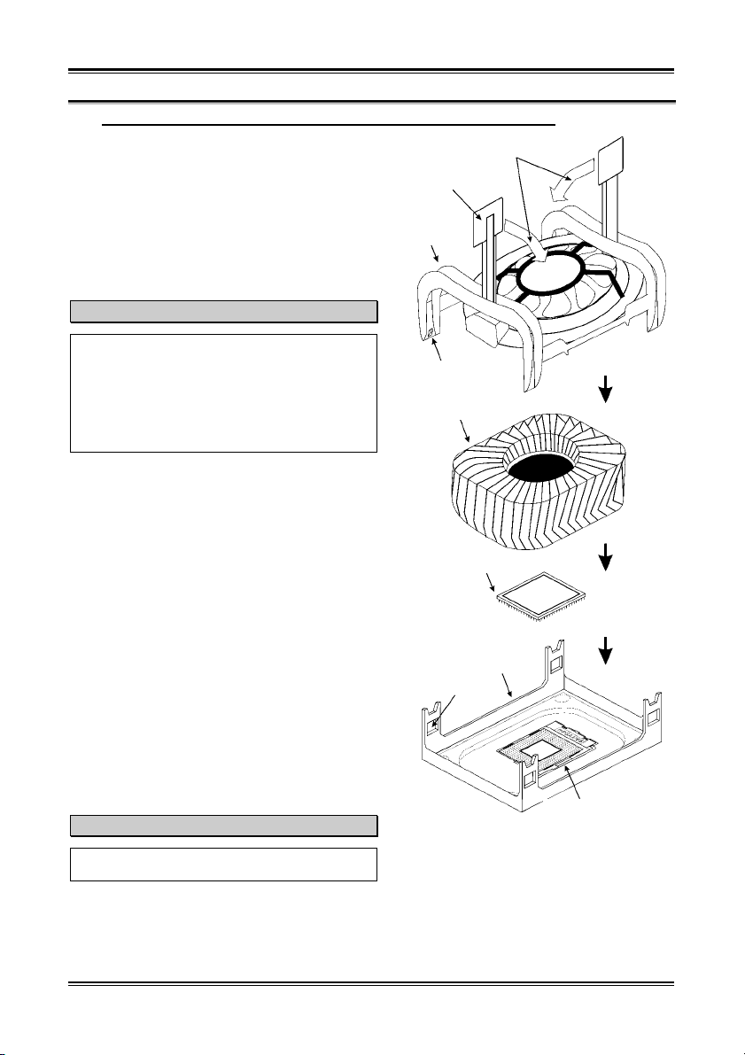
®
(2). Installazione processore Pentium
Questa scheda madre fornisce una presa “Socket
478” ZIF (Zero Insertion Force – forza d’inserimento
zero) per installare il processore Intel
4 e base di supporto dispersore di calore
Spingere verso il basso per chiudere
®
Pentium® 4. Il
Fermaglio dispersore di calore
processore acquistato dovrebbe essere fornito di
dispersore di calore e ventolina per il raffreddamento.
In caso contrario acquistare un dispersore di calore
specifico per la presa Socket 478 Pentium
®
. Fare
riferimento alla figura 2 per installare il processore.
Coperchio supporto
dispersore di calore
1. Localizzare la presa Socket 478. Fissare la base di
supporto dispersore di calore sulla scheda madre.
Attenzione
Se si impiega un telaio progettato
specificatamente per il processore Pentium® 4,
prestare attenzione all’ubicazione delle borchie in
Fermagli di bloccaggio
metallo o degli spaziatori, nel caso in cui siano
già installati sul telaio. Assicurarsi di non
permettere alle borchie in metallo od agli
Dispersore di calore
spaziatori di entrare in contatto con il cavo o con
le parti del circuito stampato.
2. Tirare di lato la leva della presa del processore
allontanandola dalla presa; poi sollevarla di 90
gradi. Inserire il processore con il corretto
orientamento. Non sforzare per inserire il
processore poiché si adatta solamente in un dato
orientamento. Chiudere la leva della presa mentre
si trattiene il processore.
Presa Socket 478 CPU
3. Mettere il dispersore di calore a faccia in giù sul
processore finché lo copre completamente.
4. Mettere il coperchio di supporto del dispersore di
calore sul dispersore di calore. Assicurarsi che tutti
quattro i fermagli, su ciascun lato del coperchio di
supporto, si inseriscano nei fori di bloccaggio.
5. Spingere verso il basso i fermagli di bloccaggio su
Base di supporto
Foro di bloccaggio
ciascun lato del coperchio di supporto in modo da
fissarlo alla base di supporto. Prestare attenzione
alla direzione in cui si spingono i fermagli.
6. Il coperchio di supporto e la base del dispersore di
calore dovrebbero ora essere fissate saldamente
l’uno all’altra, contenendo al loro interno il
dispersore di calore.
Leva presa CPU
Attenzione
Figura 2. Installazione del processore P4
Non dimenticare di impostare la corretta
frequenza BUS e multiplier per il processore.
Socket 478 e del suo dispersore di calore sulla
base di supporto.
SR7-8X
Page 23
Six Languages Quick Installation Guide
1-19
(3). Installazione della scheda madre sul telaio
Dopo avere installato il processore sulla scheda madre si può iniziare a fissare la scheda madre sul telaio.
Innanzi tutto è necessario fissare la scheda madre al telaio. La maggior parte dei telai ha una base sulla
quale sono presenti diversi fori di montaggio che permettono di fissare in modo accurato la scheda madre
e, allo stesso tempo, di prevenire corto circuiti. Impiegare le borchie o gli spaziatori attaccati al telaio per
fissare la scheda madre.
(4). Installazione della memoria di sistema
Questa scheda madre fornisce tre slot d’espansione
di memoria DDR DIMM da 184 pin. La memoria
DDR SDRAM minima è di 64 MB e quella massima
è di 2 GB (unbuffered, PC 2700) oppure di 3 GB
(unbuffered, PC 1600/PC 2100). Ci sono tre prese
modulo memoria sulla scheda madre (per un totale
di sei file).
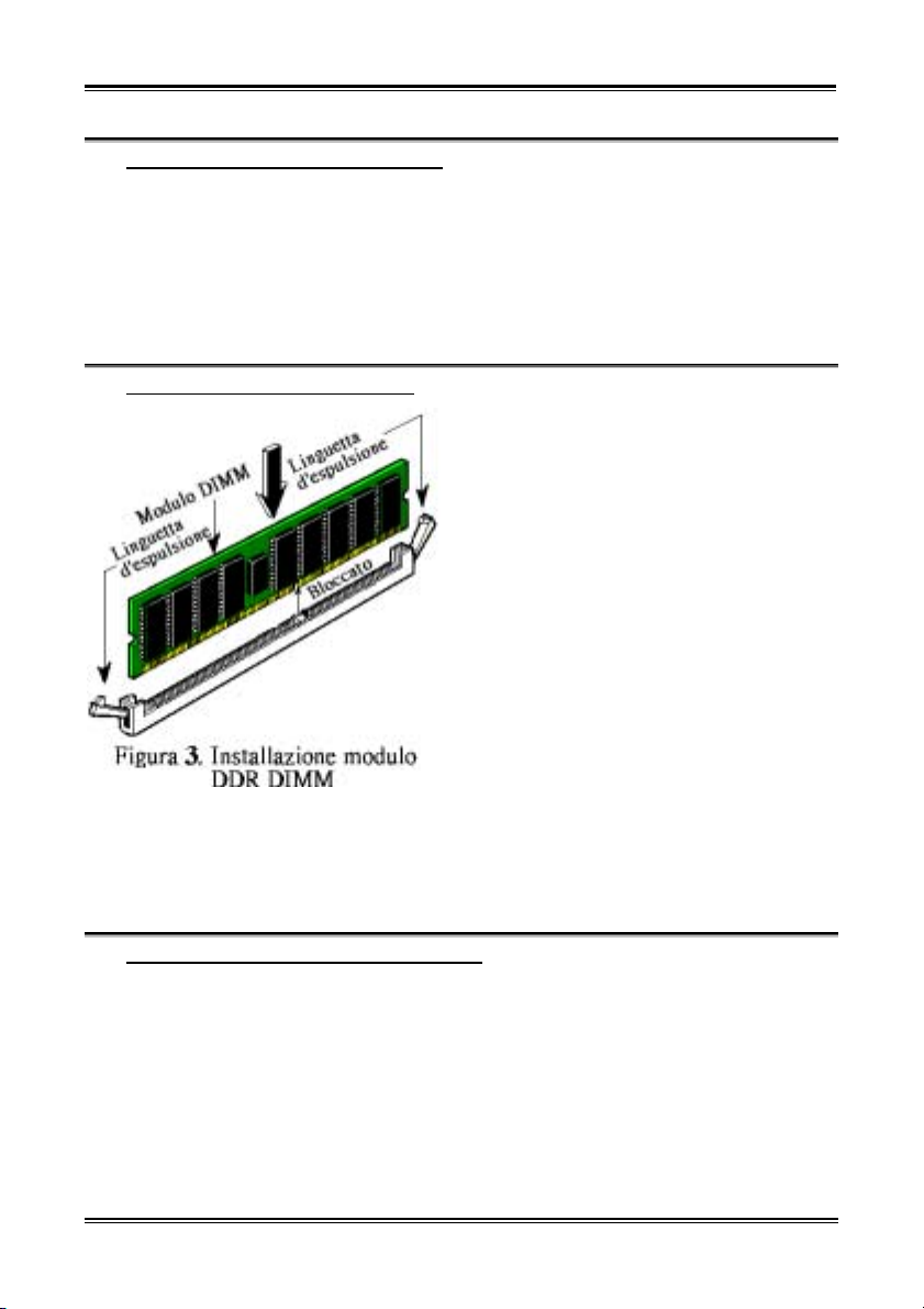
Inserire il modulo DDR DIMM nello slot
d’espansione come mostrato dell’illustrazioneNotare come il modulo è imperniato nella presa.
Fare riferimento alla Figura 3 per dettagli. Ciò
assicura che ci sia un unico modo per collegare il
modulo DDR DIMM. Premere con fermezza il
modulo DDR DIMM nello slot DDR DIMM,
assicurandosi che il modulo sia inserito
completamente nello slot DDR DIMM.
Per questi moduli si suggerisce di inserire i chip
elettronici in ordine da DIMM1 a DIMM3.
Per completare l’installazione dell’hardware del sistema, bisogna collegare tutti i cavi delle attrezzature
necessarie ai relativi collettori e connettori sulla scheda madre.
(5). Connettori, collettori, interruttori ed adattatori
All’interno della copertura di ogni computer ci sono diversi cavi e prese che devo essere collegati. Questi
cavi e prese sono solitamente collegati uno ad uno ai connettori situati sulla scheda madre. E’ necessario
prestare particolare attenzione a qualunque orientamento del collegamento che possono avere i cavi e, se
necessario, notare la posizione del primo pin del connettore. Si installeranno alcuni adattatori per
particolari necessità quali l’adattatore SCSI, AGP, eccetera. Quando si installano gli adattatori sugli slot
della scheda madre, si ricorda di fissarli con le viti anche sul pannello posteriore del telaio.
Per informazioni dettagliate si prega di fare riferimento alla versione integrale del Manuale utente.
User’s Manual
Page 24
Chapter 1
1-20
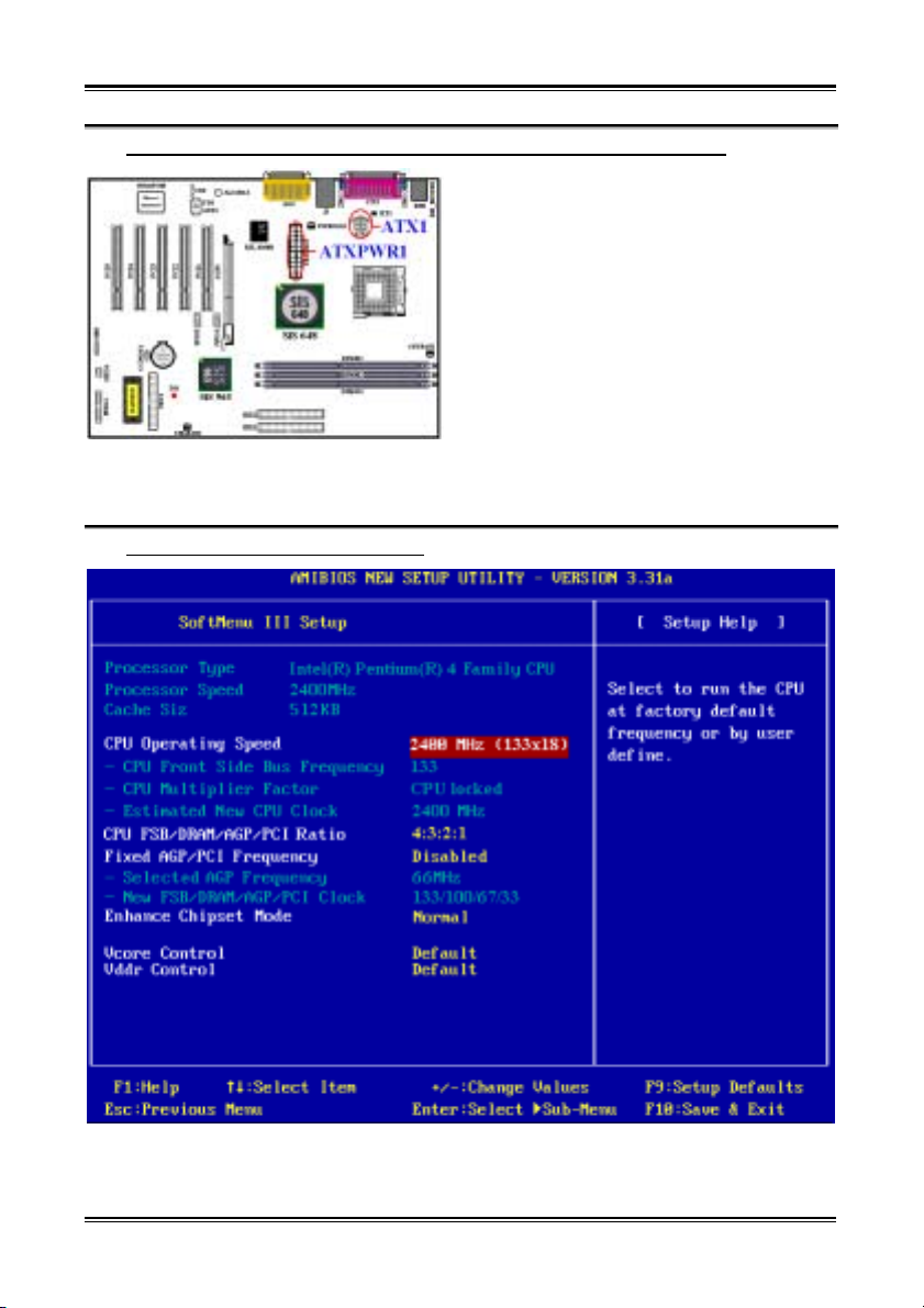
(6). Collegamento dei connettori d’alimentazione ai connettori ATX1 ed ATXPWR1
La scheda madre SR7-8X richiede una fornitura
d’alimentazione diversa dalla solita (fornitura
d’alimentazione progettata per l’utilizzo di
processori Pentium
®
4 ). E’ un’alimentazione di
nuova progettazione ATX1 +12VDC con una
capacità di almeno 300W, 20A +5VDC per sistemi
caricati pesantemente ed almeno 720mA +5VSB per
supportare alcune funzioni speciali.
Collegare qui il connettore dalla sorgente
d’alimentazione ai connettori ATXPWR1 ed
ATX12V1 Ricordarsi che è necessario spingere fino
in fondo il connettore della sorgente d’alimentazione
ATX con i connettori ATXPWR1 e ATX1,
assicurando così un buon collegamento.
Nota: Controllare la posizione e l’orientamento.
™
(7). Impostazione CPU [SOFT MENU
III]
Quando l’hardware è stato installato completamente, accendere il computer ed andare alla voce
SoftMenu III Setup」del BIOS per impostare i parametri del processore. Per informazioni dettagliate si
prega di fare riferimento alla versione integrale del Manuale utente.
SR7-8X
Page 25
Six Languages Quick Installation Guide
1-21
1-6. Краткое руководство по установке SR7-8X
Благодарим за приобретение системной платы ABIT. Эта системная плата предназначена для
процессоров Intel
SDRAM объемом до 2 Гбайт (без буферизации, PC 2700) или до 3 Гбайт (без буферизации, PC
1600/PC 2100).
Более подробные сведения о материнской плате приведены в руководстве пользователя. Краткое
руководство по установке предназначено для опытных специалистов. Если вы собираете
компьютер впервые, ознакомьтесь сперва с руководством пользователя или попросите техника
помочь в настройке компьютерной системы.
®
Pentium® 4. Она поддерживает архитектуру Intel® Socket 478 с памятью DDR
(1). Расположение компонентов SR7-8X
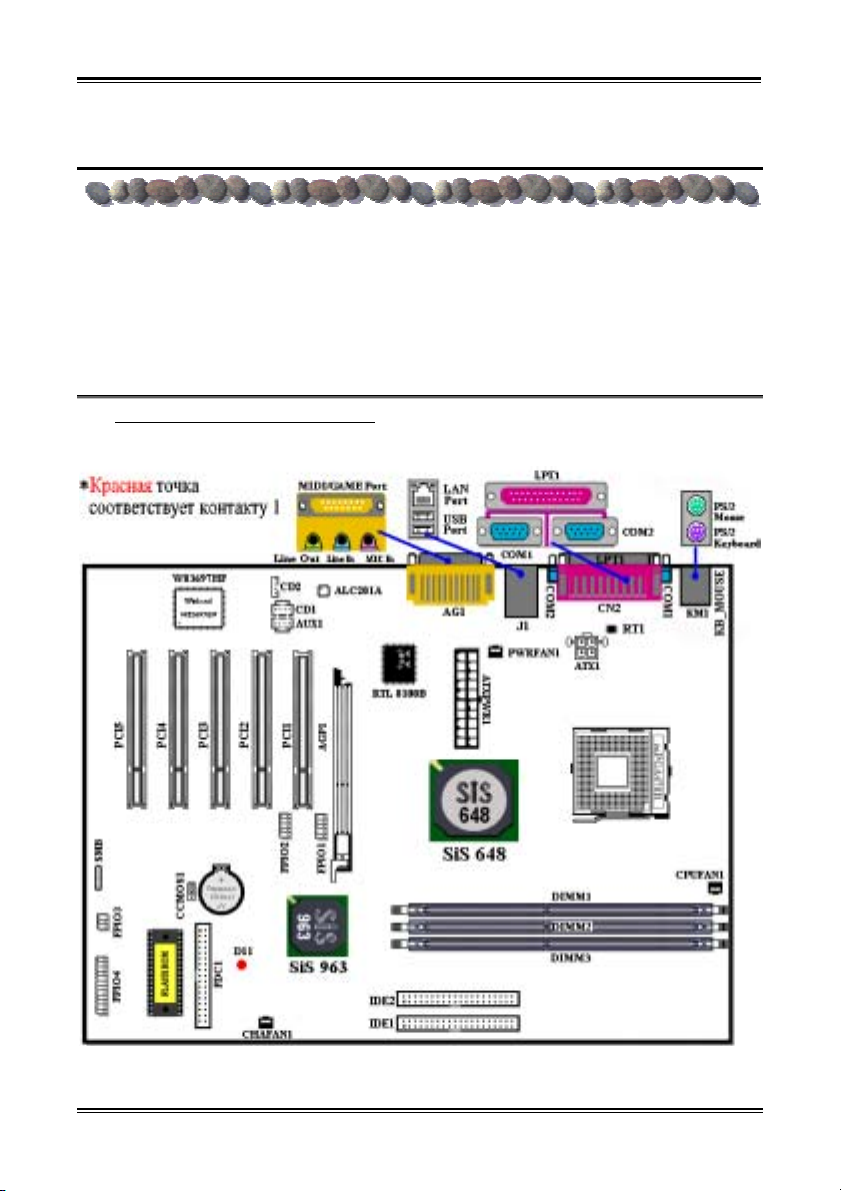
На рис. 1 показана схема расположения основных компонентов SR7-8X.
Рисунок 1. Схема расположения компонентов SR7-8X
User’s Manual
Page 26
Chapter 1
2
4
1-22
®
(2). Установка процессора Pentium
4 и крепежного основания радиатора
На этой системной плате используется гнездо ZIP
(с нулевым усилием установки) типа 'Socket 478'
для процессора Intel
®
Pentium® 4. В комплект
приобретаемого процессора должны входить
радиатор и вентилятор. В противном случае
следует приобрести радиатор и вентилятор,
предназначенные для процессора Pentium
разъемом 'Socket 478'. При установке процессора
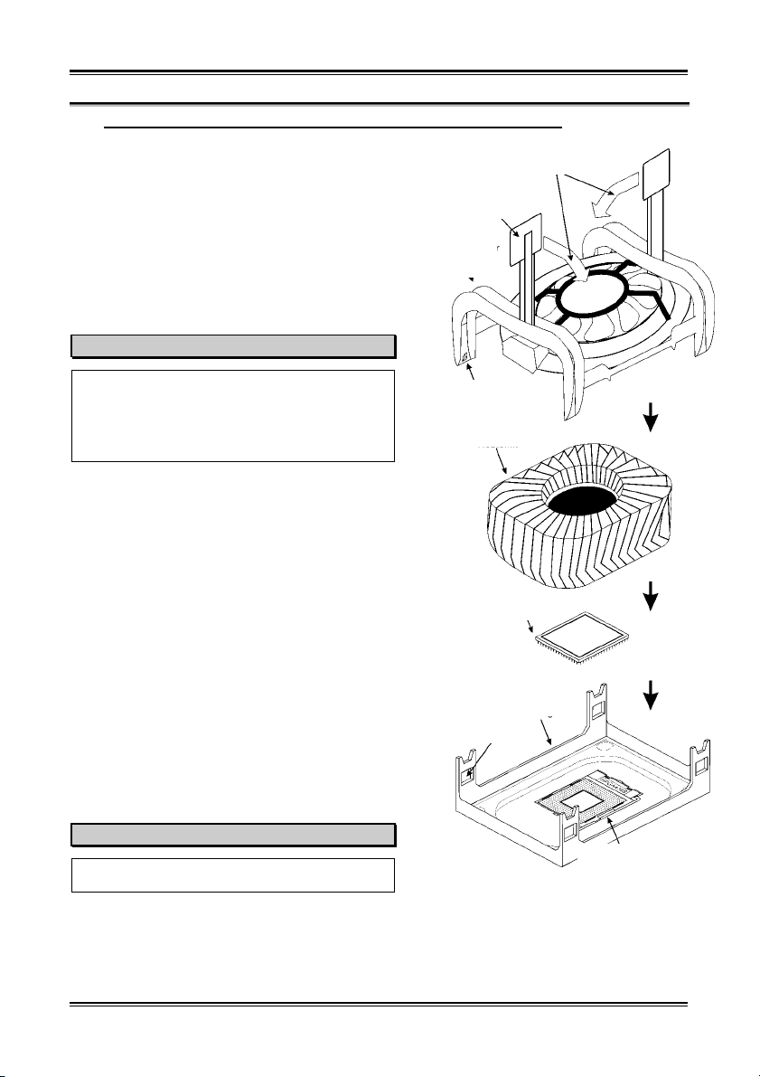
ориентируйтесь по рисунку 2.
1. Найдите на плате гнездо 'Socket 478'.
Зафиксируйте крепежное основание радиатора на
®
4 с
Прижимная крышка
радиатора
Прижмите для фиксации
Фиксирующий
зажим радиатора
системной плате.
Внимание
При использовании корпуса специально
предназначенного для Pentium® 4 обратите внимание на
расположение металлических вставок или распорок,
если они уже установлены в корпус. Не допускайте
контакта металлических вставок или распорок с
проводниками или деталями печатной платы.
. Сместите рычаг гнезда процессора в сторону от
гнезда, а затем поверните его вверх на 90
градусов. Вставьте процессор, ориентировав его
надлежащим образом. Устанавливая процессор,
Фиксатор
Радиатор
не прикладывайте чрезмерных усилий. Его
установка возможна только в одном положении.
Прижав процессор сверху, опустите рычаг
гнезда.
3. Поместите радиатор плоской стороной на
процессор так, чтобы процессор был полностью
Процессор с
закрыт.
. Поместите прижимную крышку радиатора на
радиатор. Все четыре фиксатора по обеим
сторонам прижимной крышки должны
находиться на уровне крепежных отверстий.
5. Прижмите вниз фиксирующие зажимы по обеим
сторонам прижимной крышки до их фиксации в
крепежном основании. Следите за направлением,
в котором Вы прижимаете зажимы.
6. Крышка и основание должны быть надежно
скреплены, фиксируя радиатор.
Крепежное основание
радиатора
Крепежное отверстие
Внимание
Не забудьте установить для процессора
надлежащую частоту шины и множитель.
SR7-8X
Рычаг гнезда процессора
Рис. 2. Установка процессора P4 с разъемом
Socket 478 и радиатора для него на крепежное
основание.
Page 27
Six Languages Quick Installation Guide
1-23
(3). Установка материнской платы в корпус
После установки процессора на материнскую плату можно начинать установку материнской
платы в корпус. Большая часть корпусов оборудована основанием, в котором проделаны
монтажные отверстия, которые позволяют надежно закрепить материнскую плату и предотвратить
короткие замыкания. Для крепления материнской платы к основанию используются винты и
прокладки.
(4). Установка модулей памяти
На плате имеется три 184-контактных гнезда
расширения DDR DIMM для памяти.
Минимальный объем памяти равен 64 Мбайт,
максимальный объем равен 2 Гбайт (без
буферизации, PC 2700) или 3 Гбайт (без
буферизации, PC 1600/PC 2100) DDR SDRAM.
На плате присутствует три гнезда для модулей
памяти (шесть групп блоков памяти).
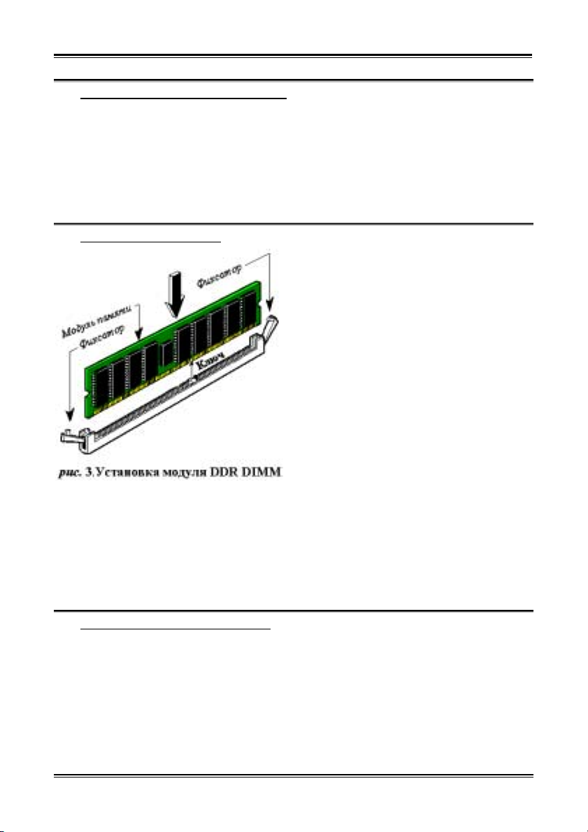
Установите модуль памяти DDR DIMM в гнездо
расширения, как показано на рисунке. Обратите
внимание, что модуль фиксируется в гнезде.
Более подробно процесс установки показан на
рис. 5. Таким образом, гарантируется
единственно возможный способ установки
модуля DDR DIMM. Вставьте модуль DDR
DIMM в гнездо DDR DIMM; и убедитесь, что
модуль надежно установлен в гнездо DDR
DIMM.
Рекомендуется устанавливать модули памяти последовательно в направлении от DIMM1 к
DIMM3.
Подключите все необходимые кабели для подключения устройств к соответствующим разъемам
на материнской плате, чтобы завершить установку аппаратуры вашей системы.
(5). Разъемы, переключатели и адаптеры
Внутри корпуса компьютера необходимо расположены несколько кабелей и вилок, которые
необходимо подключить. Обычно эти кабели подключаются к разъемам, расположенным на
материнской плате. При подключении любого кабеля необходимо обращать внимание на
расположение первого контакта разъема. Для особых целей могут потребоваться специальные
адаптеры, например, адаптер SCSI, адаптер AGP и т.п.. При установке адаптеров в гнезда
материнской платы закрепите их на задней панели с помощью винтов.
За более подробной информацией обращайтесь к полному руководству пользователя.
User’s Manual
Page 28
Chapter 1
1-24
(6). Подключение кабелей питания к разъемам ATX1 и ATXPWR1
Система питания SR7-8X отличается от
стандартной (блок питания для процессоров
®
Pentium
4). Это новый стандарт ATX1 +12VDC
с возможностью выдачи 300Вт, 20A +5В= для
систем с высокой нагрузкой и 720mA +5В для
поддержки особых функций.
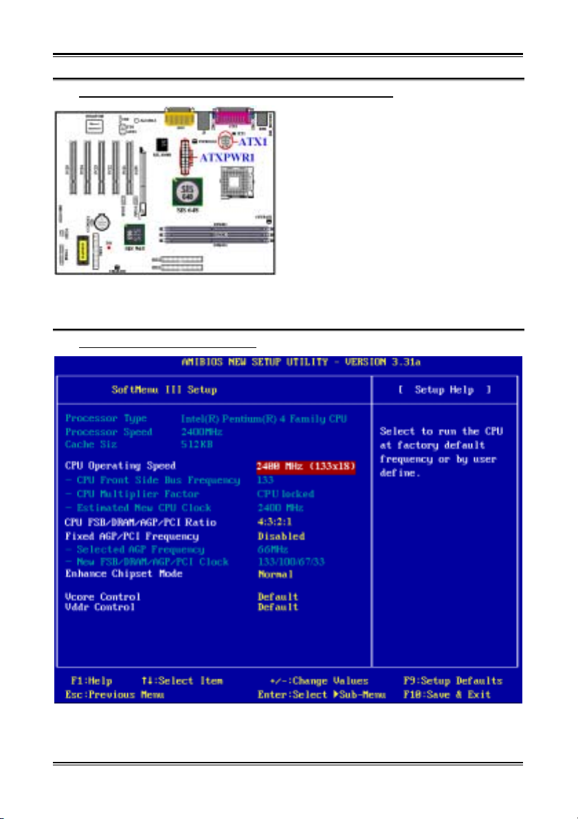
Подключите разъемы кабелей блока питания к
разъемам ATXPWR1 и ATX12V1 на
материнской плате. Не забудьте вставить
разъемы кабелей питания ATX в разъемы
ATXPWR1 и ATX1 до упора, чтобы быть
уверенными в надежности контактов.
Примечание: Обратите внимание на положение контактов и ориентацию разъема.
™
(7). Настройка CPU [SOFT MENU
III]
По окончании установки аппаратуры включите питание и перейдите в меню BIOS「SoftMenu III
Setup」, чтобы настроить параметры процессора. За более подробной информацией обращайтесь к
руководству пользователя.
SR7-8X
Page 29

Introduction of SR7-8X Features
2-1
Chapter 2. Introduction of SR7-8X Features
2-1. Features of SR7-8X Motherboard
The SR7-8X is designed for use with Intel’s latest generation of Pentium® 4 (400/533 MHz FSB) 478
pins processors. Based on the new SiS 648 chipsets (SiS 648 & SiS 963), The SiS 648 Host, Memory and
AGP Controller integrates a high performance host interface for Intel
performance memory controller, a AGP interface, and SiS MuTIOL 1G Technology connecting w/ SiS
963 MuTIOL 1G Media IO.
The SR7-8X can support external AGP slot with AGP 8X/4X capability and Fast Write Transactions. The
memory controller supports three DDR DIMMs for a maximum of up to 3 GB. It can offer bandwidth up
to 2.7 GB/s under DDR333 in order to sustain the bandwidth demand from host processor, as well as the
multi I/O masters and AGP masters.
The SR7-8X has integrateds Universal Serial Bus 2.0 Host Controllers, the Audio controller, the
ATA-133 IDE controllers, the high-speed host controller implements an EHCI interface that provides 480
Mb/s bandwidth for six USB 2.0 ports. Each of six USB ports can be automatically routed to support a
High-speed USB 2.0 devices or Low-speed USB 1.1 devices. The SR7-8X has integrated ATA-133 IDE
Master/Slave controller features Dual Independent IDE channels supporting PIO mode 0,1,2,3,4, and
Ultra DMA 33/66/100/133 MB/s. It provides two separate data paths for the dual IDE channels that
sustain the high data transfer rate in the multitasking environment.
SR7-8X offers users a robust, high performance and low cost computing-platform. Moreover, on board
10/100 Mb LAN provides high speed networking capability, and built-in 2-channel audio delivers a
multimedia solution.
This motherboard also supports five PCI slots and one AGP slot. In addition, this motherboard gives users
enormous flexibility through ABIT’s SoftMenu
able to alter both the FSB speed and the multiplier to get the CPU processing speed of your choice. This
motherboard has built-in hardware monitoring functions that monitors and protects your computer,
ensuring a safe computing environment.
™
III with plenty clock frequency selections. The user is
®
Pentium® 4 processor, a high
2-2. Specifications
1. Processor
! Supports Intel® Pentium® 4 socket 478 processor with 400 MHz/533 MHz (100 MHz/133 MHz
Quad Data Rate) CPU front side bus
2. Chipset (SiS 648 and SiS 963):
! Supports Ultra DMA 33, Ultra DMA 66, Ultra DMA 100 and Ultra DMA 133 IDE protocol
! Supports Advanced Configuration and Power Management Interface (ACPI)
User’s Manual
Page 30

Chapter 2
2-2
! Accelerated Graphics Port connector supports AGP 8X/4X Interface (1.5V) Only
! Supports 200 MHz/266 MHz/333 MHz (100 MHz/133 MHz/166 MHz Double Data Rate) memory
bus settings
3. Memory (System Memory)
! Three 184-pin DIMM slots support PC 1600/PC 2100/PC 2700 DDR SDRAM modules
! Supports up to Two unbuffered DDR DIMMs for PC 2700 DDR modules (up to 2 GB)
! Supports up to Three unbuffered DDR DIMMs for PC 1600/PC 2100 DDR modules (up to 3 GB)
4. System BIOS
! SOFT MENU™ III technology, can easily set the processor parameters
! AMI Plug and Play BIOS supports APM and Deaktop Management Interface (DMI)
! Supports ACPI (Advanced Configuration Power Interface)
! AMI BIOS
5. Audio Function
! AC’ 97 2-Channel Audio CODEC on board
6. Multi I/O Functions
! One floppy port connector (up to 2.88MB)
! Two channels of Bus Master IDE ports supporting up to four Ultra DMA 33/66/100/133 devices
! One PS/2 keyboard and PS/2 mouse connectors
! Two serial ports connectors
! One parallel port connector (Standard/EPP/ECP)
! Two USB 2.0 connectors
! One 10/100 Mb port (RJ-45 type)
! One audio connector (Line-in, Line-out, Mic-in, and MIDI/Game port)
7. Miscellaneous
! ATX form factor
! One AGP slot, five PCI slots
! Two USB header for four extra USB channels
! One built-in IrDA TX/RX header
! Two CD audio input connector
! Supports wake up by LAN
! Supports wake up by modem ring
! Supports Wake Up by RTC Alarm
! Hardware monitoring:Included fan speed, voltages, processor and system environment temperature
! Board size: 305 * 230 mm
SR7-8X
Page 31

Introduction of SR7-8X Features
# The Switching Power Supply must meet ATX 2.03 specification with ATX12V1 Power
connector.
# Supports Wake On LAN, Wake On Ring, but your ATX power supply 5V standby power must
be able to provide at least a 720mA current capacity. Otherwise, the functions may not work
normally.
# This motherboard supports the standard bus speeds of 66 MHz/100 MHz/133 MHz that are
used by specific PCI, processor and chipset specifications. Exceeding these standard bus speeds
is not guaranteed due to the specific component specifications.
# Specifications and information contained in this manual are subject to change without notice.
Note
All brand names and trademarks are the property of their respective owners.
2-3
2-3. Item Checklist
Check that your package is complete. If you discover any damaged or missing items, please contact your
retailer or dealer.
$ One ABIT SR7-8X Motherboard
$ One 80-wire/40-pin ribbon cable for master and slave Ultra DMA 133, Ultra DMA 100, Ultra DMA
66 or Ultra DMA 33 IDE devices
$ One ribbon cable for 3.5” floppy disk devices
$ One compact disc for support drivers and utilities
$ One Rear I/O shield bracket
$ One USB cable
$ One user’s manual for the motherboard
User’s Manual
Page 32
Chapter 2
2-4
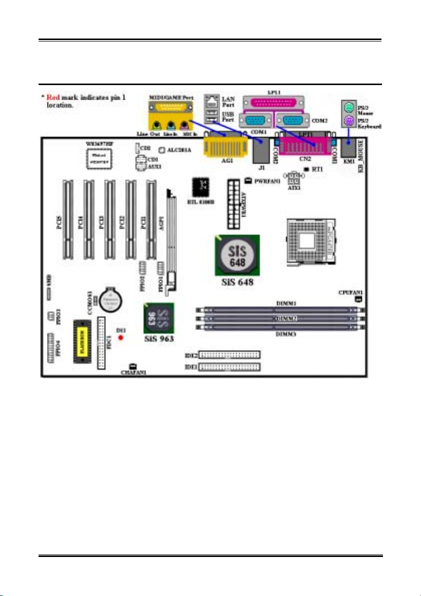
2-4. Layout Diagram for SR7-8X
SR7-8X
Figure 2-1. SR7-8X motherboard component location
Page 33

Installing the Motherboard
3-1
Chapter 3. Installing the Motherboard
This SR7-8X motherboard not only provides all standard equipment for classic personal computers, but
also provides great flexibility for meeting future upgrade demands. This chapter will introduce
step-by-step all of the standard equipment and will also present, as completely as possible, future upgrade
capabilities. This motherboard is able to support all Intel
details, see specifications in Chapter 2.)
This chapter is organized according the following features:
2-1 Install The Motherboard
2-2 Install Intel
2-3 Install System Memory
2-4 Connectors, Headers and Switches
®
Pentium® 4 processor and Heatsink Supporting-Base
®
Pentium® 4 processors now on the market. (For
%%%%
Before you install or unplug any connectors or add-on cards, please remember to turn the ATX power
supply switch off (fully turn the +5V standby power off), or take the power cord off. Otherwise, you may
cause the motherboard components or add-on cards to malfunction or be damaged.
&
Please read our instructions carefully and follow them step-by-step. Our objective is to enable the novice
computer user to perform the installation by himself. We have attempted to write this document in a very
clear, concise and descriptive manner to help overcome any obstacles you may face during installation.
This chapter contains many color drawings, diagrams and photos, we strongly recommend you read this
chapter use the PDF file that is stored on the CD-Title. Color improves the clarity and quality of the
diagrams. For the downloadable edition, as files larger than 3 MB are difficult to download, we will cut
the graphics and photo resolution to reduce the manual file size. In such this case, if your manual is
downloaded from our WEB site and not from a CD-ROM, enlarging graphics or photos will distort the
image.
Before Proceeding with the Installation
User Friendly Instructions
Diagram and Photos
%%%%
User’s Manual
Page 34
Chapter 3
3-2
3-1. Installing the Motherboard to the Chassis
Most computer chassis will have a base on which there will be many mounting holes that allows the
motherboard to be securely attached and at the same time, prevents short circuits. There are two ways to
attach the motherboard to the base of chassis:
! With studs
! Or with spacers
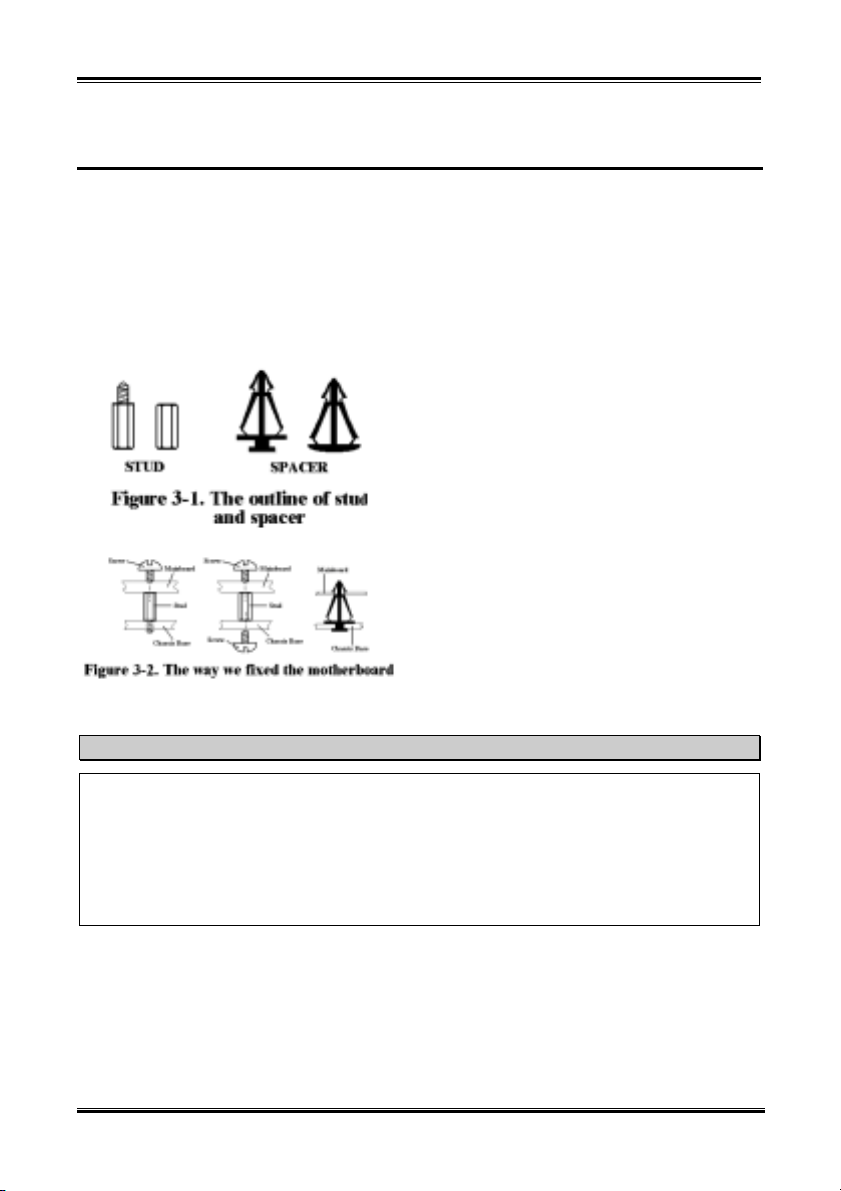
Please refer to figure 3-1, which shows the studs and spacers. There may be several types, but all look
like the figures below:
In principle, the best way to attach the motherboard
is with studs. Only if you are unable to do this
should you attach the board with spacers. Take a
careful look at the motherboard and you will see
many mounting holes on it. Line these holes up with
the mounting holes on the base. If the holes line up
and there are screw holes this means you can attach
the motherboard with studs. If the holes line up and
there are only slots, this means you can only attach
the motherboard with spacers. Take the tip of the
spacers and insert them into the slots. After doing
this to all the slots, you can slide the motherboard
into position aligned with the slots. After the
motherboard has been positioned, check to make
sure everything is OK before putting the casing back
on.
Figure 3-2 shows you the way to affix the
motherboard using studs or spacers.
Note
If the motherboard has mounting holes, but they don’t line up with the holes on the base and there are
no slots to attach the spacers, don’t worry, you can still attach the spacers to the mounting holes. Just
cut the bottom portion of spacers (the spacer they may be a little hard to cut, so be careful with your
hands). In this way you can still attach the motherboard to the base without worrying about short
circuits. Sometimes you may need to use the plastic springs to isolate the screw from the motherboard
PCB surface, because the circuit wire may be near by the hole. Be careful, don’t let the screw contact
any the printed circuit wire or parts on the PCB that are near the fixing hole, otherwise it may damage
the board or cause board malfunctioning.
SR7-8X
Page 35
Installing the Motherboard
3-3
3-2. Install Pentium® 4 Processor and Heatsink Supporting-Base
This motherboard provides a ZIF (Zero Insertion
Force) Socket 478 to install Intel
®
Pentium® 4
processor. The processor you bought should include a
heatsink and cooling fan kit along with. If that’s not
the case, buy one specially designed for Pentium
®
4
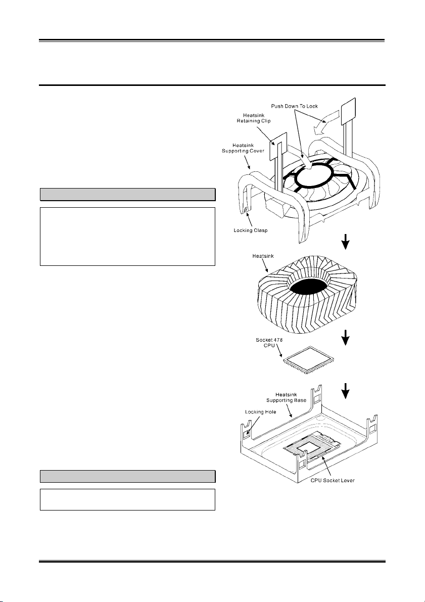
Socket 478. Please refer to figure 3-3 to install the
processor.
1. Locate the Socket 478. Fasten the heatsink
supporting-base onto the motherboard.
Attention
If you are using chassis specially designed for
Pentium® 4, please pay attention to the location of
metal studs or spacers if they are already installed
on the chassis. Be careful not let the metal studs
or spacers contact the printed circuit wire or parts
on the PCB.
2. Pull the processor socket lever sideways away
from the socket and then upwards to 90 degrees.
Insert the processor with the correct orientation.
Do not use extra force to insert processor; it only
fits in one orientation. Push down the socket lever
while holding down the processor.
3. Put the heatsink face down onto the processor until
it completely covers the processor.
4. Put the heatsink supporting-cover onto the
heatsink. Make sure all four locking clasps on each
side of the supporting cover reach in the locking
holes.
5. Push down the retaining clip on both sides of the
supporting cover to lock together with the
supporting base. Watch the direction you push
down on the clip.
6. The heatsink supporting cover and base should
now firmly lock together with the heatsink inside.
Attention
Do not forget to set the correct bus frequency and
multiple for your processor.
Figure 3-3. Installing P4 Socket 478 processor
and its heatsink onto supporting base.
User’s Manual
Page 36
Chapter 3
3-4
3-3. Installing System Memory
This motherboard provides three 184-pin DDR DIMM sites for memory expansion. The DDR DIMM
sockets support 8 M x 64 (64 MB), 16 M x 64 (128 MB), 32 M x 64 (256 MB), 64 M x 64 (512 MB), and
128 M x 64 (1024 MB) or double density DDR DIMM modules. Minimum memory is 64 MB and the
maximum memory is 2 GB (Unbuffered PC 2700 DDR Module) or 3 GB (Unbuffered PC 1600/2100
DDR Module) DDR SDRAM. There are three memory module sockets on the system board (for a total
of six banks). In order to create a memory array, following rules must be followed.
! For those modules, we suggest that you be populate DIMM1 to DIMM3 in order.
! Supports single and double density DDR DIMMs.
Table 3-1. Valid Memory Configurations
Bank Memory Module Total Memory
Bank 0, 1
(DDR DIMM1)
Bank 2, 3
(DDR DIMM2)
Bank 4, 5
(DDR DIMM3)
Total System Memory for Unbuffered PC2700 DDR DIMM
Total System Memory for Unbuffered PC1600/2100 DDR
body.
64 MB, 128 MB, 256 MB,
512 MB, 1024 MB
64 MB, 128 MB, 256 MB,
512 MB, 1024 MB
64 MB, 128 MB, 256 MB,
512 MB, 1024 MB
DIMM
64 MB ~ 1 GB
64 MB ~ 1 GB
64 MB ~ 1 GB
64 MB ~ 2 GB
64 MB ~ 3 GB
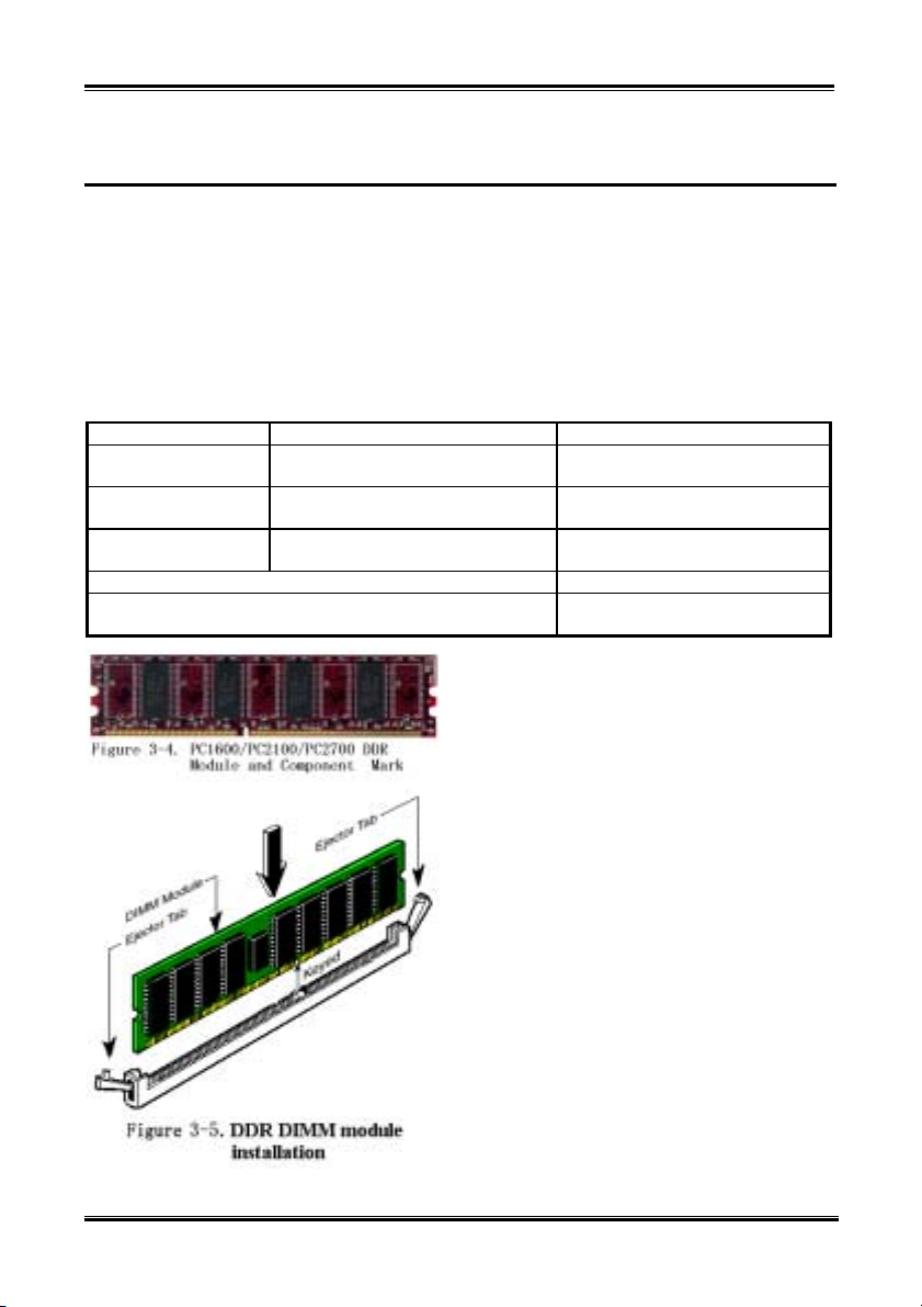
Generally, installing DDR SDRAM modules to your
motherboard is an easy thing to do. You can refer to
Figure 3-4 to see what a 184-pin PC 1600, PC 2100
& PC 2700 DDR SDRAM module looks like.
Unlike installing SIMMs, DIMMs may be
“snapped” directly into the socket. Note: Certain
DDR DIMM sockets have minor physical
differences. If your module doesn't seem to fit,
please do not force it into the socket as you may
damaged your memory module or DDR DIMM
socket.
The following procedure will show you how to
install a DDR DIMM module into a DDR DIMM
socket.
Step 1. Before you install the memory module,
please place the computer power switch in
the off position and disconnect the AC
power cord from your computer.
Step 2. Remove the computer’s chassis cover.
Step 3. Before touching any electronic components,
make sure you first touch an unpainted,
grounded metal object to discharge any
static electricity stored on your clothing or
SR7-8X
Page 37

Installing the Motherboard
Step 4. Locate your computer’s 184-pin memory expansion DDR DIMM socket.
Step 5. Insert the DDR DIMM module into the expansion socket as shown in the illustration. Note how
the module is keyed to the socket. You can refer to Figure 3-5 for the details. This insures the
DDR DIMM module will be plugged into the socket in one way only. Firmly press the DDR
DIMM module into DDR DIMM socket, making certain the module is completely seated in the
DDR DIMM socket.
Step 6. Once the DDR DIMM module has been installed, the installation is complete and the computer’s
cover can be replaced. Or you can continue to install other devices and add-on cards that are
mentioned in the following section.
Note
When you install a DDR DIMM module fully into the DDR DIMM socket, the eject tab should be
locked into the DDR DIMM module very firmly and fit into its indention on the both sides.
It is difficult to differentiate between the PC 1600, PC 2100 and PC 2700 DDR SDRAM modules from
the exterior. The only way you can identify them is to look at the sticker on the DDR SDRAM module.
The sticker will tell you which kind of structure module the DDR SDRAM is.
3-5
3-4. Connectors, Headers and Switches
Inside the case of any computer, several cables and plugs have to be connected. These cables and plugs
are usually connected one-by-one to connectors located on the motherboard. You need to carefully pay
attention to any connection orientation the cables may have and, if any, notice the position of the first pin
of the connector. In the explanations that follow, we will describe the significance of the first pin.
We will show you all of the connectors, headers and switches here, and tell you how to connect them.
Please pay attention and read the entire section for necessary information before attempting to finish all
hardware installation inside the computer chassis.
Figure 2-6 shows you all of the connectors and headers that we’ll discuss in the next section, and you can
use this diagram to visually locate each connector and header we describe.
All connectors, headers and switches mentioned here will depend on your system configuration. Some
features you may (or may not) have and need to be connected or configured depending on the peripheral.
If your system doesn't have such add-on cards or switches, you can safely ignore some special feature
connectors.
User’s Manual
Page 38
Chapter 3
3-6
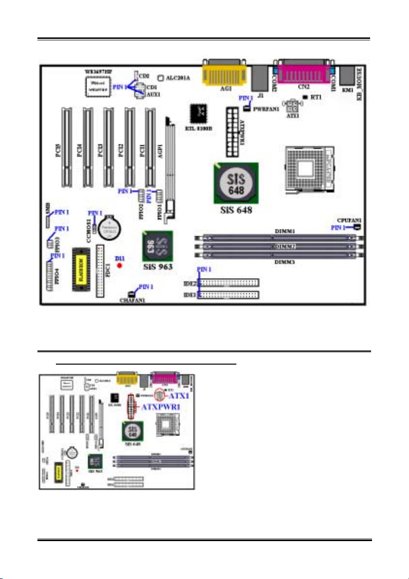
Figure 3-6. All Connectors and Headers for the SR7-8X
First, Let’s see the headers that SR7-8X uses, and what their functions are. We will show you all the
connectors and headers.
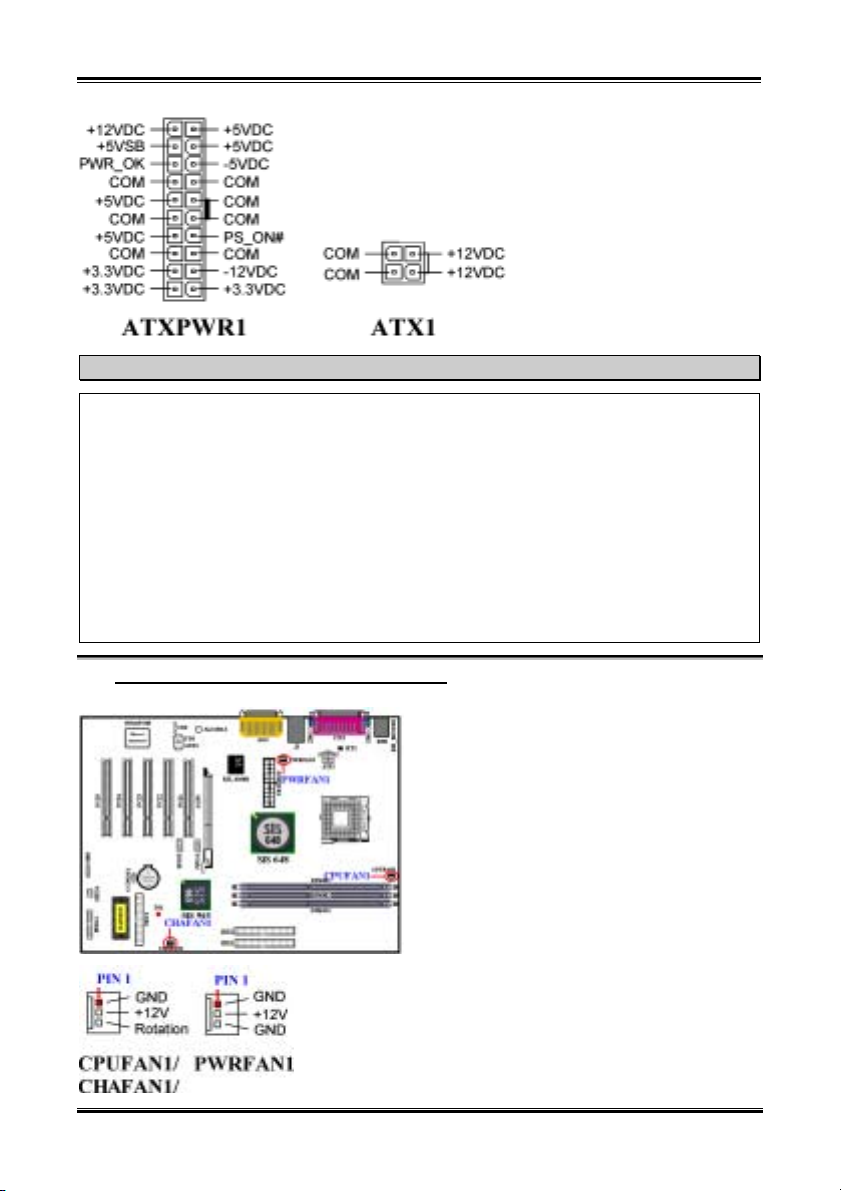
(1). ATX1 and ATXPWR1: ATX Power Input Connectors
The Pentium® 4 requires a power supplier different
from the regular one. It’s a newly designed ATX1
power with 300W, 20A +5VDC capacity at least for
heavily loaded system, and 720mA +5VSB at least
for supporting Wake-On-LAN (WOL) or
Wake-On-Ring (WOR) features.
Attach the connector from the power supply to the
ATX1 and ATXPWR1 connectors here. Remember
you have to push the connector from the ATX
power supply firmly to the end with the ATX1 and
ATXPWR1 connectors, insuring that you have a
good connection.
Note: Watch the pin position and the orientation.
SR7-8X
Page 39
Installing the Motherboard
Caution
If the power supply connectors are not properly attached to the ATX power supply, the power supply
or add-on cards may be damaged.
One end of AC power core connects to ATX power supply, and the other end (AC plug) will plug into
the wall outlet. Be aware that when facing the wall outlet, the round hole is in the middle. The right
side slot is called ground wire slot. It has a longer slot length than the left side slot. The left side slot is
called the live wire slot. You can use an electroscope to detect its polarity or you can use a voltage
meter to measure the voltage of both slot sides. If you insert an electroscope into the live wire slot, the
electroscope will light up. Using a voltage meter, you will find that the live wire slot will register a
higher voltage.
If you reverse the polarity of AC plug, it may affect the life of computer equipment, or cause an
electric shock when you touch the computer chassis. We suggest that you plug the computer AC plug
to a three-hole wall outlet for better safety and to avoid electric shock.
3-7
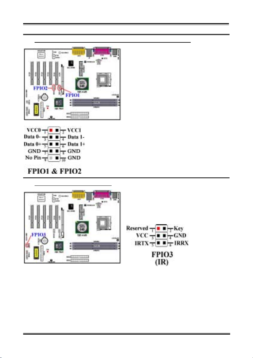
(2). CPUFAN1, CHAFAN1 and PWRFAN1 Headers
Attach the connector from the processor fan to the
header named CPUFAN1 and connector from the
front chassis fan to the header CHAFAN1. Attach
the connector from the power fan or Add-on card
cooling fan to PWRFAN1 header. You must attach
the processor fan to the processor, or your processor
will work abnormally or may be damaged by
overheating. To prevent the computer chassis
internal temperature from getting too high, also
connect the chassis fan.
Note: Watch the pin position and the orientation
User’s Manual
Page 40
Chapter 3
3-8
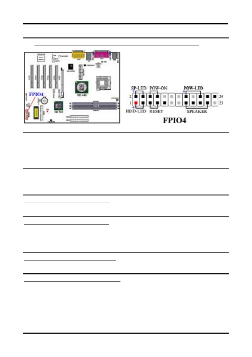
(3). FPIO1 (USB3/4) & FPIO2 (USB 5/6) Header: Additional USB Plugs Header
Thess headers are for connecting the additional USB
port plugs. Each connector can provides two
additional USB plugs. Which means, total you can
get two additional USB plugs from each connector.
You can use the special USB port expansion cable
to connect it (the cable come with the metal plate
can fixed on the back panel of computer chassis).
(4). FPIO3 Header: IR Header (Infrared)
There is a specific orientation for pins 1 through 6,
attach the connector from the IR KIT or IR device to
the IR header (FPIO3). This motherboard supports
standard IR transfer rates.
Note: Watch the pin position and the orientation
SR7-8X
Page 41
Installing the Motherboard
3-9
(5). FPIO4 Headers: The Headers for Chassis’s Front Panel Indicators and Switches
FPIO4 are for switches and indicators for the
chassis’s front panel, there are several functions that
come from this header. You have to watch the pin
position and the orientation, or you may cause LED
do not light up. Figure below shows you the FPIO4
functions of the pins.
FPIO4 (Pin 1 & 3): HDD LED Header
Attach the cable from the case’s front panel HDD LED to this header. If you install it in the wrong
direction, the LED light will not illuminate correctly.
Note: Watch the HDD LED pin position and the orientation.
FPIO4 (Pin 5 & 7): Hardware Reset Switch Header
Attach the cable from the case’s front panel Reset switch to this header. Press and hold the reset button
for at least one second to reset the system.
FPIO4 (Pin 15-17-19-21): Speaker Header
Attach the cable from the system speaker to this header.
FPIO4 (Pin 2 & 4): Suspend LED Header
Insert the two-threaded suspend LED cable into this header. If you install it in the wrong direction, the
LED light will not illuminate correctly.
Note: Watch the Suspend LED pin position and the orientation.
FPIO4 (Pin 6 & 8): Power On Switch Header
Attach the cable from the case’s front panel power on switch to this header.
FPIO4 (Pin 16-18-20): Power On LED Headers
There is a specific orientation for pins 1 through 3. Insert the three-threaded power on LED cable to this
header. Check to make sure the correct pins go to the correct connectors on the motherboard. If you
install them in the wrong direction, the power LED light will not illuminate correctly.
Note: Watch the power LED pin position and orientation.
User’s Manual
Page 42
Chapter 3
3-10
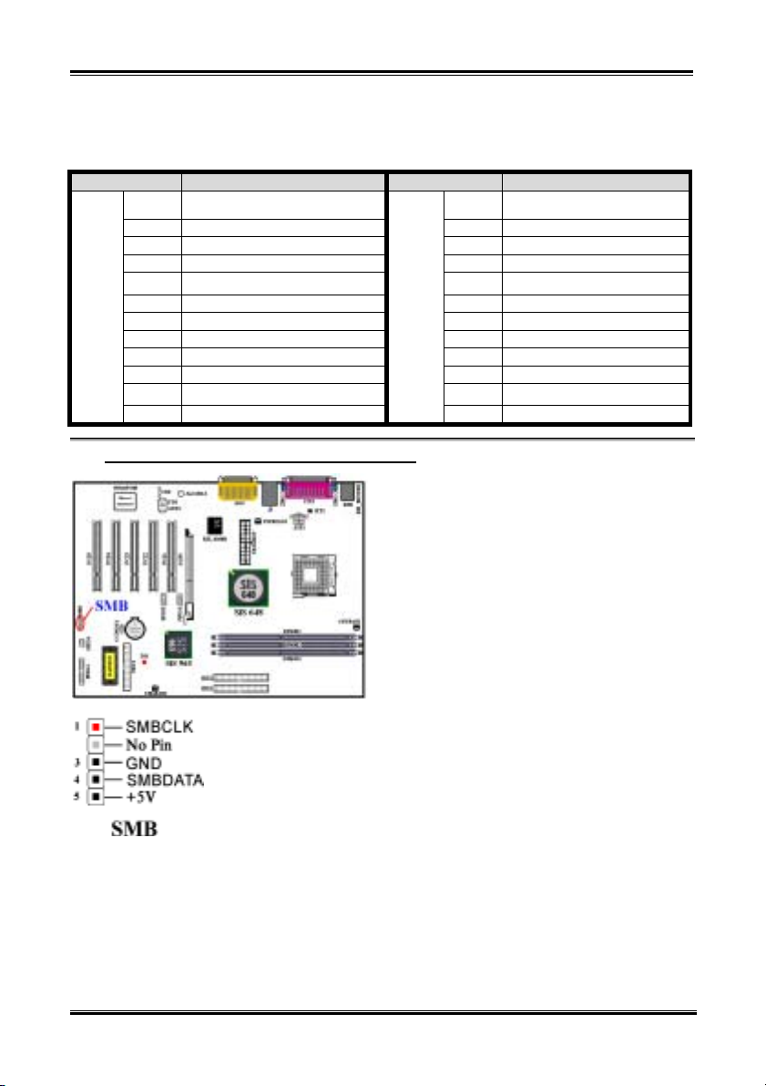
For the FPIO4 pin’s count-name list, please refer to table 3-2.
Table 3-2. FPIO4 pin count name list
PIN Name Significance of signal PIN Name Significance of signal
PIN 1 HDD LED (+) PIN 2 SP-LED (+)
PIN 3 HDD LED (-) PIN 4 SP-LED (-)
PIN 5 Reset SW (-) PIN 6 PWR-ON (+)
PIN 7 Reset SW (+) PIN 8 PWR-ON (-)
PIN 9 No Connection PIN 10
PIN 11 No Pin PIN 12 No Pin
FPIO4
PIN 13 No Pin PIN 14 No Pin
PIN 15 Speaker (+5V) PIN 16 PWR LED (+)
PIN 17 Speaker (GND) PIN 18 No Pin
PIN 19 Speaker (GND) PIN 20 PWR LED (-)
PIN 21 Speaker (Driver) PIN 22 No Connection
PIN 23 No Pin
(6). SMB: System Management Bus (SM-Bus) Header
FPIO4
PIN 24 No Connection
This header is reserved for the system management
bus (SM-Bus). The SM-Bus is a specific
implementation of an I
bus, this means that multiple chips can be connected
to the same bus and each one can act as a master by
initiating a data transfer. If more than one master
simultaneously tries to control the bus, an arbitration
procedure decides which master gets priority. You
can connect the devices which utilizes the SM-Bus.
Note: Watch the pin position and the orientation
No Pin
2
C bus. I2C is a multi-master
SR7-8X
Page 43
Installing the Motherboard
3-11
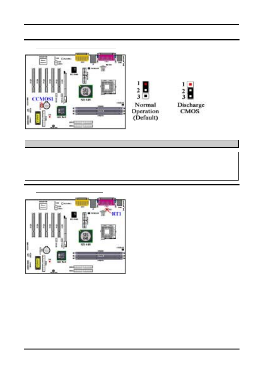
(7). CCMOS1: CMOS Discharge Jumper
Before you clear the CMOS, you have to first turn the power off (including the +5V standby power).
Otherwise, your system may work abnormally.
After updating your BIOS and before boot up, please clear the CMOS first. Then put the jumper to its
default position. After that, you can reboot your system and ensure that your system is working fine.
(8). RT1: Temperature Thermistor
Jumper CCMOS1 discharge CMOS memory. When
you install the motherboard, make sure this jumper
is set for normal operation (pin 1 and 2 shorted). See
figure below.
Note
The RT1 is used to detect the system environment
temperature. You can see the readings in the BIOS
or in the hardware monitoring application main
screen.
User’s Manual
Page 44
Chapter 3
3-12
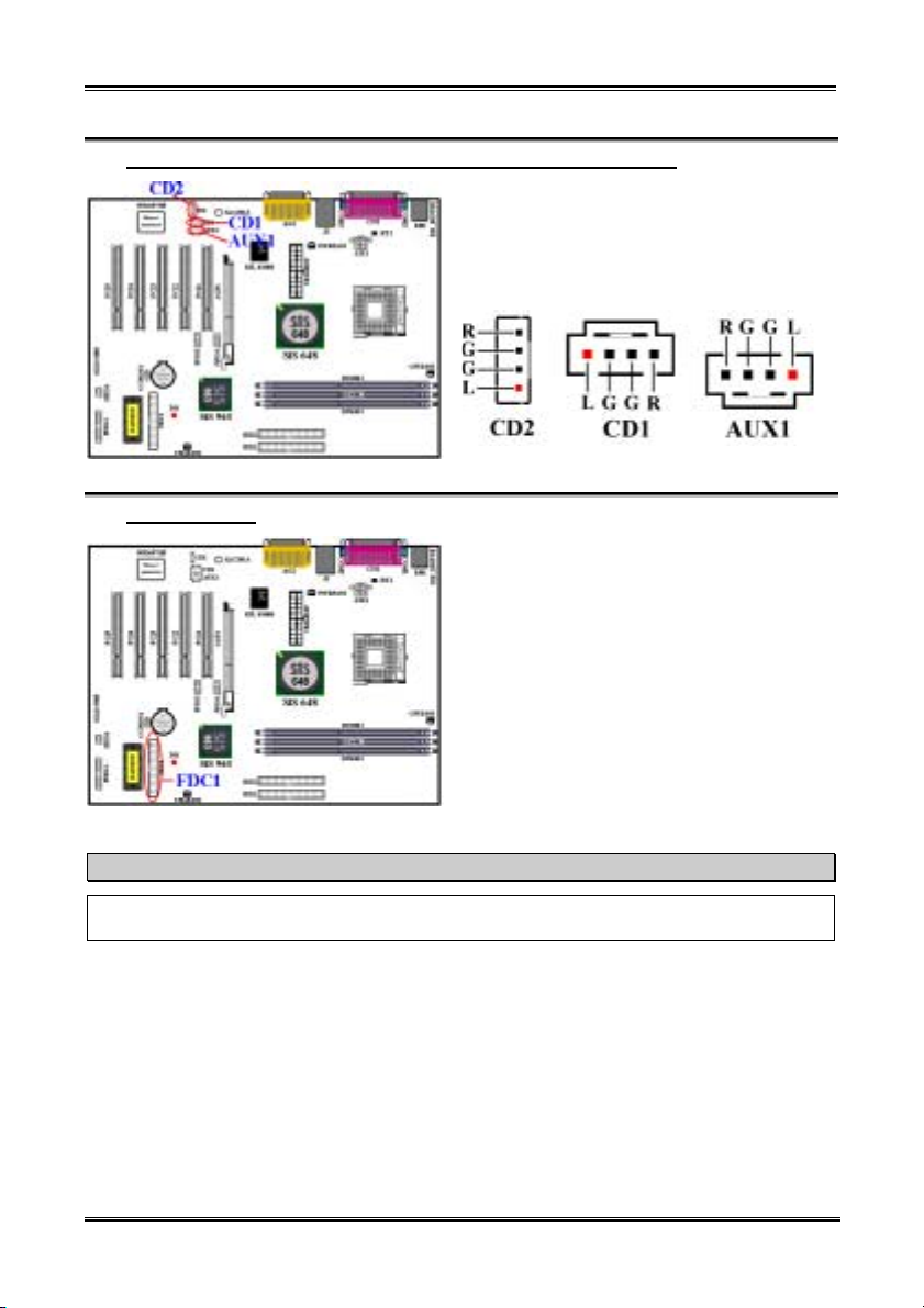
(9). CD1, CD2 and AUX1: CD audio and auxiliary audio signal input headers
These connectors connect to the audio output of
internal CD-ROM drive or add-on card audio output.
There are two types connectors can let you choose
to connect CD audio.
(10). FDC1 Connector
This 34-pin connector is called the “floppy disk
drive connector”. You can connect a 360K, 5.25”,
1.2M, 5.25”, 720K, 3.5’’, 1.44M, 3.5” or 2.88M,
3.5” floppy disk drive.
A floppy disk drive ribbon cable has 34 wires and
two connectors to provide the connection of two
floppy disk drives. After connecting the single end
to the FDC1, connect the two connectors on the
other end to the floppy disk drives. In general,
people only install one floppy disk drive on their
computer system.
Note
A red mark on a wire typically designates the location of pin 1. You need to align the wire pin 1 to the
FDC1 connector pin 1, and then insert the wire connector into the FDC1 connector.
SR7-8X
Page 45
Installing the Motherboard
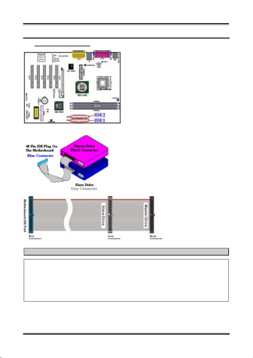
(11). IDE1and IDE2 Connectors
This motherboard provides two IDE ports (IDE1 &
IDE2) to connect up to four IDE devices in Ultra
DMA 133 mode by Ultra DMA 66 ribbon cables.
Each cable has 40-pin 80-conductor and three
connectors, providing two hard drive connections
with the motherboard. Connect the single end (blue
connector) at the longer length of ribbon cable to the
IDE port on motherboard, and the other two ends
(gray and black connector) at the shorter length of
the ribbon cable to the connectors on hard drives.
If you want to connect two hard drives together
through one IDE channel, you must configure the
second drive to Slave mode after the first Master
drive. Please refer to the HDD documentation for jumper settings. The first drive connected to IDE1 is
usually referred to as “Primary Master”, and the second
drive as “Primary Slave”. The first drive connected to
IDE2 is referred to as “Secondary Master” and the
second drive as “Secondary Slave”.
Keep away from connecting one legacy slow speed device,
like CD-ROM, together with another hard disk drive on
the same IDE channel; this will decrease your integral
system performance.
3-13
Figure 3-7. Ultra DMA 66
Ribbon Cable Outline
Note
! The Master or Slave status of the hard disk drive is set on the hard disk itself. Please refer to the
hard disk drive user’s manual.
! To connect Ultra DMA 133 and Ultra DMA 100 devices on IDE1and IDE2, an Ultra DMA 66
cable is required.
! A red mark on a wire typically designates the location of pin 1. You need to align the wire pin 1 to
the IDE connector pin 1 before inserting the wire connector into the IDE connector.
User’s Manual
Page 46
Chapter 3
3-14
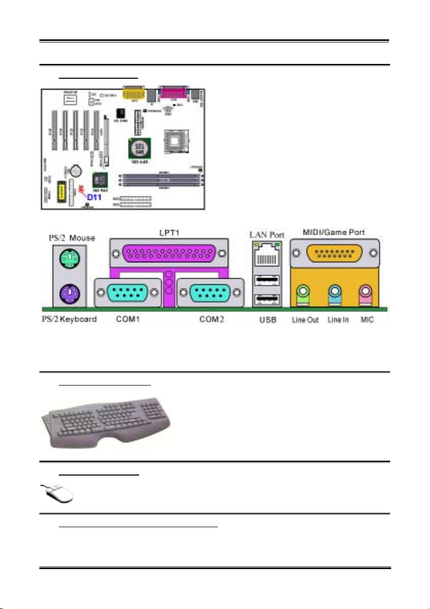
(12). D11: 5V Standby LED
D11 will light up after the power switch is pressed,
this LED will show you the 5V standby power
situation.
Figure 3-8. SR7-8X back panel connectors
Figure 2-8 shows the SR7-8X back panel connectors. These connectors are used for connecting outside
devices to the motherboard. We will describe which devices will attach to these connectors below.
(13). PS/2 Keyboard Connector
(14). PS/2 Mouse Connector
Attach a PS/2 mouse to this 6-pin Din-connector.
(15). Serial Port COM1 & COM2 Port Connectors
This motherboard provides two COM ports, you can connect an external modem, mouse or other devices
that support this communication protocol to these connectors.
SR7-8X
Attach a PS/2 keyboard connector to this 6-pin Din-connector.
If you use an AT keyboard, you can go to a computer store to
purchase an AT to ATX converter adapter, then you can
connect your AT keyboard to this connector. We suggest you
use a PS/2 keyboard for best compatibility.
Page 47
Installing the Motherboard
3-15
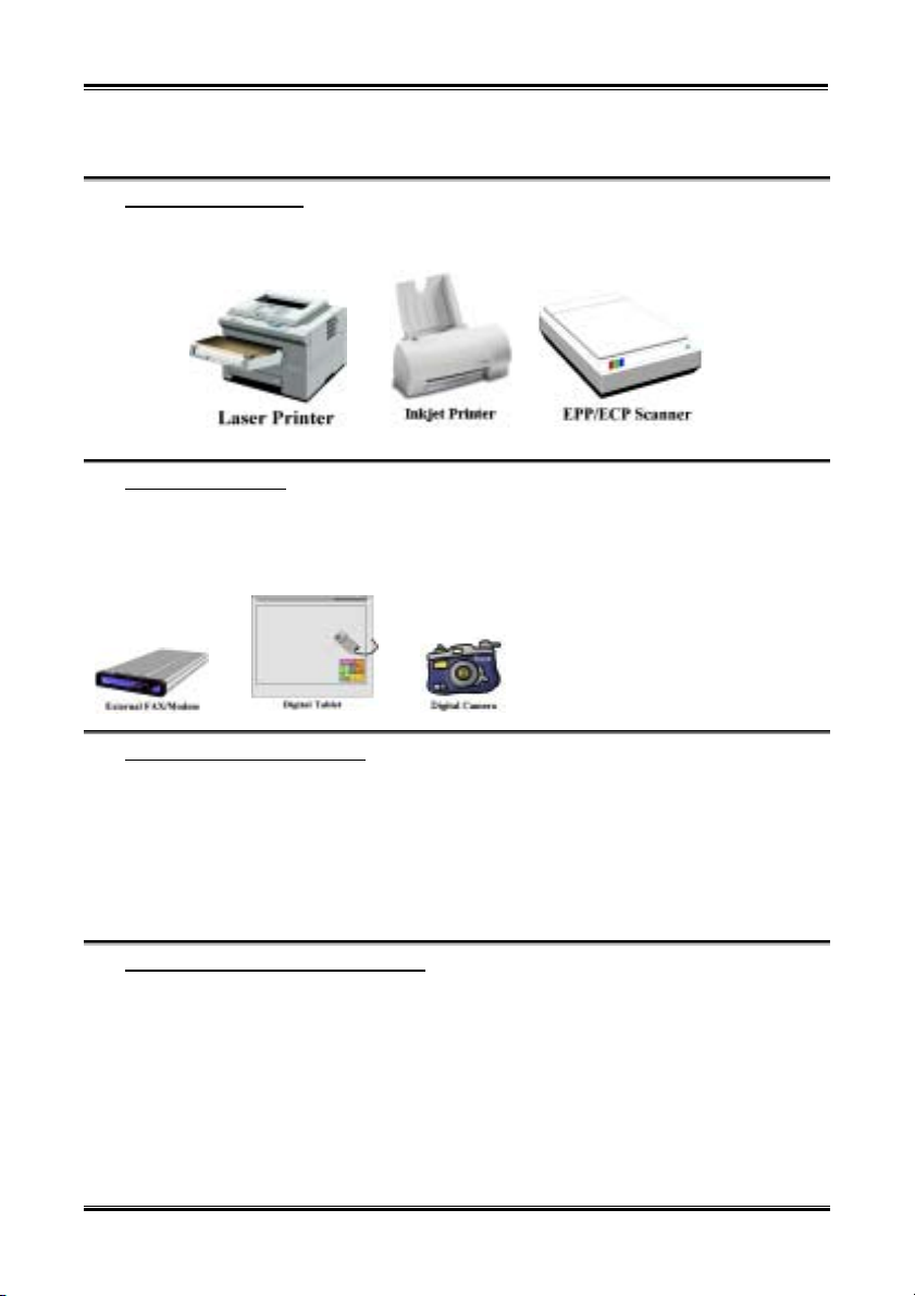
You can decide which external devices you want to connect to COM1 and COM2. Each COM port can
only have one device connected at a time.
(16). Parallel Port Connector
This parallel port is also called an “LPT” port, because it usually connects to the printer. You can connect
other devices that support this communication protocol, like an EPP/ECP scanner, etc.
(17). USB Port Connectors
This motherboard provides two USB ports. Attach the USB connector from the individual device to these
connectors.
You can attach USB devices such as a, scanner, digital speakers, monitor, mouse, keyboard, hub, digital
camera, joystick etc. to one of each USB
connector. You must make sure your
operating system supports this feature and
you may need to install an additional
driver for individual devices. In Please
refer to your device user’s manual for
detailed information.
(18). 10/100 Mb LAN Port Connector
This motherboard provides built-in 10/100 Mb LAN port, this jack is for connecting the RJ-45 cable from
the local area network hub to your computer. We suggest you use the category 5 UPT (Unshielded
Twisted Pair) or STP (Shielded Twisted Pair) cable to make this connection. The connection length from
the hub to the computer is best to be kept under 100 meter.
The green LED shows the connection situation. If the network active well, this LED will light on. The
yellow LED shows if the data is active or not. If the computer is translating or receiving data from the
network, this LED will flicker.
(19). Line Out, Line In and Mic In Connector
Line Out connector: You can connect an external stereo speaker signal input plug to this connector, or
you can connect the plug from here to the stereo audio equipment AUX signal input socket. Remember,
the motherboard does not have a built in amplifier to drive the speaker, so you must use a speaker that has
a built in amplifier, or you may not hear any sound or only a small volume of sound from the speaker.
Line In Connector: You can connect the TV adapter audio output signal, or external audio sources, like
a CD walkman, video camcorder, VHS recorder audio output signal plug to this connector. Your audio
software can control the input level for the line-in signal.
Mic In Connector: You can connect the plug from the microphone to this connector. Do not connect
other audio (or signal) sources to this connector.
User’s Manual
Page 48

Chapter 3
3-16
(20). MIDI/GAME Port Connector
You can connect your joystick, game pad, or other simulation hardware device DIN 15-pin plugs to this
connector. Please refer to the further connection notes of the device’s user's manual for further detailed
information.
Note
This chapter contains many color drawing diagram and photos, we strongly recommend you to read
this chapter use the PDF file we gave you that store in the CD-Title. It will provide you the better look
and clearly color identify.
SR7-8X
Page 49
Introducing the BIOS
4-1
Chapter 4. Introducing the BIOS
The BIOS is a program located on a Flash Memory chip on the motherboard. This program will not be
lost when you turn the computer off. This program is also referred to as the boot program. It is the only
channel the hardware circuit has to communicate with the operating system. Its main function is to
manage the setup of the motherboard and interface card parameters, including simple parameters such as
time, date, hard disk drive, as well as more complex parameters such as hardware synchronization, device
operating mode, SOFT MENU
normally, or will operate at its best, only if all of these parameters are correctly configured through the
BIOS.
Don’t change the parameters inside the BIOS unless you fully understand the meanings
'
and consequences
The parameters inside the BIOS are used to setup the hardware synchronization or the
device-operating mode. If the parameters are not correct, they will produce errors, the computer will
crash, and sometimes you will even not be able to boot the computer after it has crashed. We
recommend that you do not change the parameters inside the BIOS unless you are very familiar with
them. If you are not able to boot your computer anymore, please refer to the section “CCMOS1
Discharge Jumpr” in Chapter 3 to see how to discharge the CMOS date.
When you start the computer, the BIOS program controls it. The BIOS first operates an auto-diagnostic
test called POST (Power On Self Test) for all of the necessary hardware. It then configures the parameters
of the hardware synchronization, and detects all of the hardware. Only when these tasks are completed
does it give up control of the computer to the program to the next level, which is the operating system
(OS). Since the BIOS is the only channel for hardware and software to communicate, it is the key factor
for system stability, and in insuring that your system performs at its best. After the BIOS has achieved the
auto-diagnostic and auto-detection operations, it will display the following message:
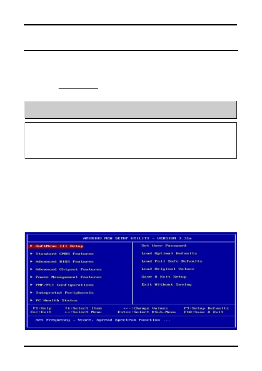
The message will be displayed for three to five seconds, if you press the Del key, you will access the
BIOS Setup menu. At that moment, the BIOS will display the following message:
™
III features and setup of processor speed. The computer will operate
DEL : Setup
Figure 4-1. CMOS Setup Utility Menu Screen Shot
User’s Manual
Page 50
Chapter 4
4-2
In the BIOS Setup main menu of Figure 3-1, you can see several options. We will explain these options
step by step in the following pages of this chapter, but let us first see a short description of the function
keys you may use here:
! Press Esc to quit the BIOS Setup.
! Press ↑↓←→ (up, down, left, right) to choose, in the main menu, the option you want to confirm
or to modify.
! Press F10 when you have completed the setup of BIOS parameters to save these parameters and to
exit the BIOS Setup menu.
! Press Page Up/Page Down or +/- keys when you want to modify the BIOS parameters for the
active option.
Note
Parts of the screenshot may not same as you see on your screen, because the BIOS version may
change periodically. However, most of the functions covered in this manual will work. We suggest
that you go to our WEB site often to see if there are new manual releases. Then you can check the
newly updated BIOS items.
Computer Knowledge: CMOS Data
Maybe you have heard somebody saying that his or her CMOS DATA was lost. What is the CMOS? Is
it important? The CMOS is the memory used to store the BIOS parameters that you have configured.
This memory is passive. You can read its data, and you can also store data in it. But this memory has
to be powered by a battery, in order to avoid any loss of its data when the computer is turned off.
Since you may have to change the CMOS battery when it is out of power and if doing so, you will
lose all CMOS data, therefore, we recommend that you write down all the parameters of your
hardware, or put a label with these parameters on your hard disk.
SR7-8X
Page 51
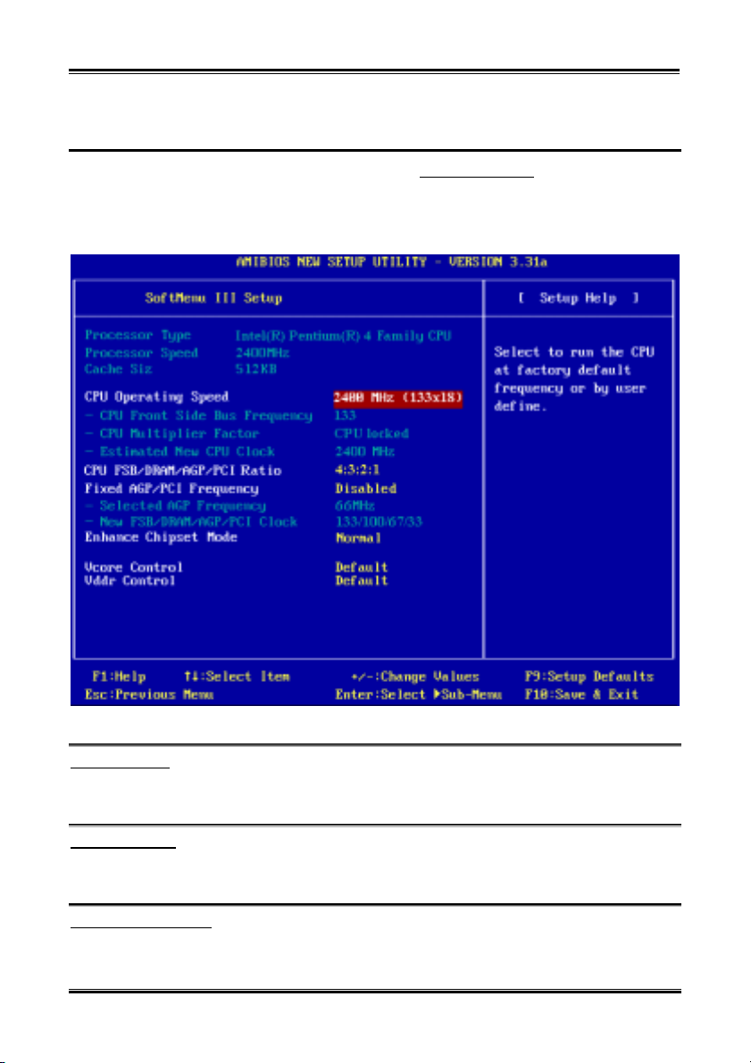
Introducing the BIOS
4-3
4-1. SOFT MENU™ III Setup
™
The processor can be setup through a programmable switch (SOFT MENU
traditional manual hardware configuration. This feature allows the user to more easily complete the
installation procedures. You can install the processor without configuring any jumpers or switches. The
processor must be setup according its specifications. In the first option, you can press <Enter> at any
time to display all the items that can be chosen for that option.
III
) that replaces the
™
III Setup Menu Screen Shot
Processor Type:
Figure 4-2. CPU SOFT MENU
This item will automatically show the processor type you installed. You can’t make any changes to this
item.
Processor Speed:
This item will automatically show the processor internal frequency currently running. You can’t make
any changes to this item.
CPU Operating Speed:
This option sets the processor speed. In this field, the processor speed is indicated like this: Processor
Speed (External Clock x Multiplier Factor). This item will automatically show the processor speed
User’s Manual
Page 52
Chapter 4
4-4
according the type and speed of your processor, or you can choose the User Define, then the following
items will be available to set.
User defined external clock and multiplier factor:
® User Defined:
%%%%
The wrong settings of the multiplier and external clock in certain circumstances may cause processor
damage. Setting the working frequency higher than the specifications of PCI or processor may cause
abnormal memory module functioning, system hangs, hard disk drive data loss, abnormal functioning
of the VGA card, or abnormal functioning with other add-on cards. Using non-specification settings
for your processor is not the intention of this explanation, for which should be used for engineering
testing only, and not for normal operation.
If you use non-specification settings for normal operation, your system may not be stable, and may
affect system reliability. Also, we do not guarantee the stability and compatibility for settings that are
not within specification, and any damage of any elements on the motherboard or peripherals is not our
responsibility.
CPU Front Side Bus Frequency:
You can increase the processor clock speed here. This means that you can independently increase the
processor FSB clock speed. The DEC (decimal) numbers from 100 to 200 are available, with the
default setting at 100 or 133 depends on the CPU you used. You can change this setting to increase
processor FSB clock speed. The processor FSB speed above the standard bus speed is supported, but
not guaranteed due to processor specifications.
CPU Multiplier Factor:
The multiplier factors for this motherboard are: Auto ( 8.0x ( 10.0x ( 11.0x ( …. ( 24.0x.
(These factors vary with the different type and specification of the processor installed)
Some processors may have the multiplier factor locked, so there is no way to choose a higher
multiplier factor. This item will show the “CPU locked” message.
Estimated new CPU Clock:
This item will show you the frequency that according settings from the item “CPU Front Side Bus
Frequency” and “CPU Multiplier factor”.
War ning
Note
%%%%
CPU FSB/DRAM/AGP/PCI Ratio:
Seven options are available: 3:3:2:1 ( 3:4:2:1 ( 3:5:2:1 ( 3:6:2:1 ( 4:3:2:1 ( 4:4:2:1 ( 4:5:2:1.
The default setting is 3:3:2:1 or 4:3:2:1. This item lets you set the processor Front Side Bus, DRAM,
AGP and PCI clock ratio. It correlates with the processor FSB clock you set. Many of options are
available, you can choose the divider ratio you want. In this case (4:3:2:1), the DRAM clock will be the
processor FSB clock divided by 4 and times 3. AGP clock will be the processor FSB clock divided by 4
and times 2. The PCI clock will be the processor FSB clock divided by 4 and times 1.
SR7-8X
Page 53

Introducing the BIOS
%%%%
These two options 3:6:2:1 and 4:6:2:1 in CPU FSB/DRAM/AGP/PCI Ratio is for engineering testing
purpose only and considered as non-specification settings. Do not set these two options for normal
operation, your system may not be stable, and may affect system reliability. Also, we do not guarantee
the stability and compatibility for settings that are not within specification, and any damage of any
elements on the motherboard or peripherals is not our responsibility.
Fixed AGP/PCI Frequency:
Two options are available: Disabled ( Enabled. The default setting is Disabled. This item can set the
fixed DRAM/AGP/PCI frequency ratio. You can decide which settings are proper for you.
Selected AGP Frequency:
You can increase the AGP clock speed here. This means that you can independently increase the AGP
clock speed. The frequencies from 66 MHz to 100 MHz are available and one step is 1 MHz. You can
change this setting to increase AGP clock speed. You can enter the frequency number by numeric key,
and press the <Enter> key to confirm and input the frequency. AGP speed above the standard AGP
bus speed is supported, but not guaranteed due to the AGP specs.
New FSB/DRAM/AGP/PCI clock:
This item will show you the new FSB/DRAM/AGP/PCI clock frequency that according settings from
the item “Fixed DRAM/AGP/PCI frequency”
War ning
%%%%
4-5
Enhance Chipset Mode:
Four options are available: Normal ( Fast ( Fixed in 83MHz ( Fixed in 144 MHz. The default setting
is Fast. This item can set the data transfer speed between the northbridge and southbridge, the faster item
you choose will enchance the chipset transfer rate. When the item “Fixed AGP/PCI Frequency” set to
Enabled, this item will only left two items to select: Fixed in 83MHz and Fixed in 144 MHz.
Normally, we do not recommend that you use the “User Define” option to setup processor speed and PCI
clock. This option is for setup of future processors whose specifications are still unknown. The
specifications of all present processors are included in the default settings. Unless you are very familiar
with all processor parameters, it is very easy to make mistakes when you define the external clock and the
multiplier factor by yourself.
Solution in case of booting problem due to invalid clock setup:
Normally, if the processor clock setup is wrong, you will not be able to boot. In this case, turn the system
off then on again. The processor will automatically use its standard parameters to boot. You can then
enter the BIOS Setup again and set up the processor clock. If you can’t enter the BIOS setup, you must
try turning the system on a few times (3 ~ 4 times) or press “INSERT” key when turning on and the
system will automatically use its standard parameters to boot. You can then enter BIOS SETUP again and
set up the new parameters.
When you change your processor:
This motherboard has been designed in such a way that you can turn the system on after having inserted a
CPU in the socket without having to configure any jumpers or DIP switches. But if you change your CPU,
normally you just have to turn off the power supply (mechanical off), change the CPU and then, set up the
CPU parameters through SOFT MENU
same brand and type), we offer you two methods to successfully complete the CPU change operation.
User’s Manual
™
III. However, if the new CPU is slower than the old one (and is
Page 54

Chapter 4
4-6
Method 1: Setup up the CPU for the lowest speed for its brand. Turn the power supply off (mechanical
off) and change the CPU. Then turn the system on again, and set up the CPU parameters
through SOFT MENU
™
III.
Method 2: Since you have to open the computer case when you change the processor, it could be a good
idea to use the CCMOS jumper to erase the parameters of the original processor and enter
BIOS Setup to set up processor parameters again.
Attention
After setting up the parameters and leaving the BIOS SETUP, and having verified that the system can
be booted, do not press the Reset button or turn off the power supply. Otherwise the BIOS will not
read correctly, the parameters will fail and you must enter SOFT MENU
™
III again to set up the
parameters all over again.
Vcore Control:
Four options are available: Default ( Default +5% ( Default +10% ( Default +15%. The default
setting is Default.
Vddr Control:
Four options are available: Default ( 2.6V ( 2.7V ( 2.8V. The default setting is Default.
SR7-8X
Page 55
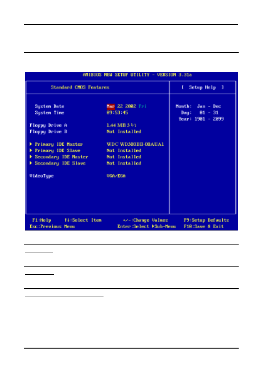
Introducing the BIOS
4-7
4-2. Standard CMOS Features Setup Menu
This contains the basic configuration parameters of the BIOS. These parameters include date, hour, VGA
card, floppy disk and HDD settings.
Figure 4-3A. Standard CMOS Features Setup Menu Screen Shot
System Date:
You can set the date in this item: month (mm), date (dd) and year (yy).
System Time:
You can set the time in this item: hour (hh), minute (mm) and second (ss).
Floppy Driver A & Floppy Driver B:
If you have installed the floppy disk drive here, then you can select the type of floppy drive it can support.
Five options are available: Not Installed ( 1.2 MB 51/4 ( 720 KB 31/2 ( 1.44 MB 31/2 ( 2.88 MB
31/2. The BIOS will automatically detect the devices installed on FDD connectors.
Primary IDE Master / Slave and Secondary IDE Master / Slave:
These items have a sub-menu to let you choose further options. You can refer to figure 4-3B to check
what options are available.
User’s Manual
Page 56
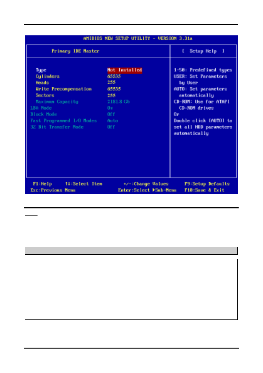
Chapter 4
4-8
Figure 4-3B. IDE Primary Master Setup Menu Screen Shot
Type:
Four options are available: Auto ( CDROM ( ARMD ( User. You can choose the device type in this
item, generally we suggestion you to choose “Auto” to let the BIOS automatically detect the devices.
When you set it to Auto then the detailed parameters of the HDD will be shown in the remaining items of
this menu.
Note
) A new IDE HDD must be first formatted, otherwise it can’t do the read/write. The basic step in
using a HDD is to run FDISK, and then FORMAT the drive. Most current HDDs have already
been subjected to low-level format at the factory, so you can probably skip this operation.
Remember though, the primary IDE HDD must have its partition set to active within the FDISK
procedure.
* If you are using an old HDD that is already formatted, auto detection can’t detect the correct
parameters. You may need to do a low-level format or set the parameters manually, and then check
if the HDD is working.
! ARMD means: ATAPI Removeable Media Device. Such as: IDE ZIP, IDE LS120, etc.
SR7-8X
Page 57

Introducing the BIOS
4-9
Cylinders:
When disks are placed directly above one another along the shaft, the circular vertical “slice” consisting
of all the tracks located in a particular position is called a cylinder. You can set the number of cylinders
for a HDD. The minimum number you can enter is 0, the maximum number you can enter is 65535.
Heads:
This is the tiny electromagnetic coil and metal pole used to create and read back the magnetic patterns on
the disk (also called the read/write head). You can configure the number of read/write heads. The
minimum number you can enter is 0, the maximum number you can enter is 255.
Write Precompensation:
The minimum number you can enter is 0, the maximum number you can enter is 65535.
Sectors:
The minimum segment of track length that can be assigned to stored data. Sectors usually are grouped
into blocks or logical blocks that function as the smallest units of data permit. You can configure this item
to sectors per track. The minimum number you can enter is 0, the maximum number you can enter is 255.
Maximum Capacity:
This item will show the maximum capacity of your storage device.
LBA (Logical Block Addressing) mode:
Two options are available: Off ( On. The default setting is Off. You can select Auto for a hard disk >
512 MB under DOS and Windows environment. Select Off under Netware and UNIX environment.
The earlier LBA mode can support HDD capacities of up to 8.4GB, and this mode uses a different
method to calculate the position of disk data to be accessed. It translates Cylinders (CYLS), Heads and
Sectors into a logical address where data is located. The Cylinders, Heads, and Sectors displayed in this
menu do not reflect the actual structure of the hard disk, they are just reference values used to calculate
actual positions. Currently, all high capacity hard disks support this mode, that’s why we recommend you
use this mode. Currently, the BIOS can support the INT 13h extension function, enabling the LBA mode
to support hard disk drive capacities exceeding 128 GB.
Block Mode:
Two options are available: Auto ( Off. The default setting is Off. Block mode is also called block
transfer, multiple commands, or multiple sector read/write. If your IDE hard drive supports block mode
(most new drives do), select Auto for automatic detection of the optimal number of block read/writes per
sector the drive can support.
Fast Programmed I/O Modes:
Seven options are available: Auto ( 0 ( 1 ( 2 ( 3 ( 4 ( 5. The default setting is Auto. The BIOS
can auto-detect the transfer mode of the IDE devices in order to set its data transfer rate. You can select
the PIO mode from Mode 0 to Mode 4 of the IDE devices in order to set its data transfer rate.
User’s Manual
Page 58
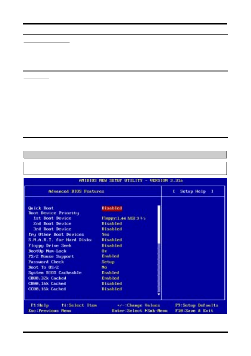
Chapter 4
4-10
32 Bit Transfer Mode:
Two options are available: Off ( On. The default setting is Off. Select On can enable 32 bit access to
maximize the IDE hard disk data transfer rate.
Back to Standard CMOS Features Setup Menu Here:
Video Type:
Five options are available: absent(VGA/EGA ( CGA 40x25 ( CGA 80x25 ( Mono. The default
setting is VGA/EGA. You can set your monitor display typr here.
4-3. Advanced BIOS Features Setup Menu
In each item, you can press <Enter> at any time to display all the options for this item.
Attention
Advanced BIOS Features Setup Menu has already been set for maximum operation. If you do not
really understand each of the options in this menu, we recommend you use the default values.
SR7-8X
Figure 4-4A. Advanced BIOS Features Setup Menu Upper Screen Shot
Page 59
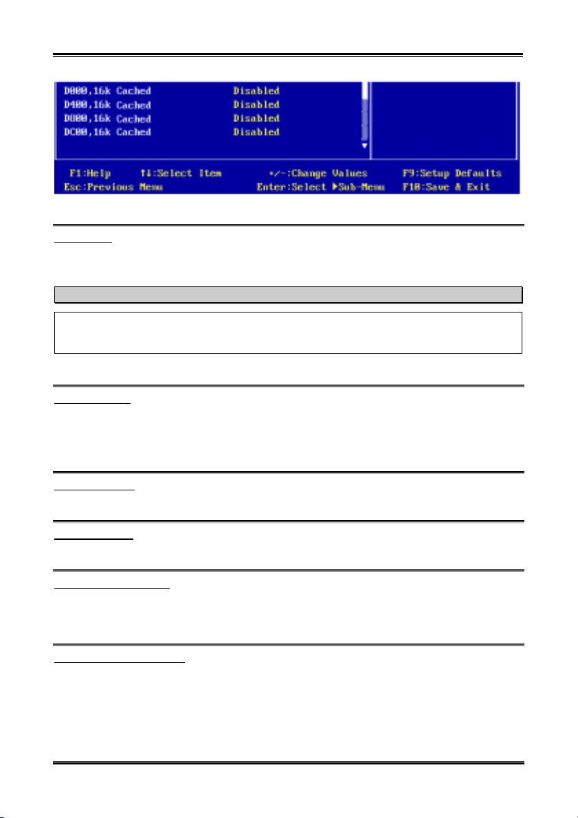
Introducing the BIOS
Figure 4-4B. Advanced BIOS Features Setup Menu Lower Screen Shot
4-11
Quick Boot:
Two options are available: Disabled or Enabled. The default setting is Enabled. Select Enabled to skip
memory test then you can enjoy the convenience of quick boot function.
When you start to get in the boot sequence, press <F6> key one time, then you can see the “Select
First Boot Device” menu show up. Choose the first boot device you want then press <Enter> key to
continue the boot sequence.
How to use the Quick Boot function?
Boot Device Priority:
1st Boot Device:
When the computer boots up, the BIOS attempts to load the operating system from these items: floppy
disk drive A, LS120, ZIP100 devices, hard drive C, SCSI hard disk drive or CD-ROM. The BIOS will
automatically detect the boot devices exist in the system, then it will display the result. At that time, you
can select the device that you want to use it as the 1st boot device.
2nd Boot Device:
Description is the same as the “1st Boot Device”.
3rd Boot Device:
Description is the same as the “1st Boot Device”.
Try Other Boot Devices:
Two options are available: Yes or No. The default setting is Yes. This setting allows the BIOS to try to
boot devices other than the three which are listed in the above 1st, 2nd and 3rd Boot Devices. If you set to
Disabled, the BIOS will boot from only the three kinds of boot devices that are set above.
S.M.A.R.T. for Hard Disks:
Two options are available: Disabled or Enabled. The default setting is Disabled. SMART
(Self-Monitoring Analysis and Reporting Technology) is a techniques which warns users of the HDD’s
defects and informs the users to transfer HDD’s data to other places. Therefore, this technique results in
improving the confidence in data preservation and the HDD itself. Therefore, if you make sure your HDD
has supports this feature, then set this item to Enabled. This allows the operating system to take the
necessary precautions and warn the user. For detailed information of your HDD specs, please read the
User’s Manual
Page 60

Chapter 4
4-12
HDD’s user’s manual or contact the dealer.
Floppy Drive Swap:
Two options are available: Disabled or Enabled. The default setting is Disabled. When this feature is
enabled, you don’t need to open the computer case to swap the position of floppy disk drive connectors.
Drive A can be set as drive B and drive B can be set as drive A.
Floppy Driver Seek:
Two options are available: Disabled or Enabled. The default setting is Disabled. When the computer
boots up, the BIOS detects if the system has a FDD or not. When this item is set to “Enabled”, if the
BIOS detects no floppy drive, it will display a floppy disk drive error message. If this item is disabled, the
BIOS will skip this test.
BootUp Num-Lock:
® Off: At boot up, the Numeric Keypad is in cursor control mode.
® On: At boot up, the Numeric Keypad is in numeric mode. (Default Settings)
PS/2 Mouse Support:
Two options are available: Disabled or Enabled. The default setting is Enabled. If you want to free the
INT 12 for other device use, then you can select Disabled to free INT 12.
Password Check:
Two options are available: Setup or Always. The default setting is Setup. After you have created a
password through “Set User Password”, this option will deny access to your computer system (Always)
or modification of computer BIOS setup (Setup) by unauthorized users.
® Setup: When you choose Setup, a password is required only when accessing the BIOS Setup. If
® Always: When you choose Always, a password is required each time the computer boots up. If the
To disable security, select “Set User Password” at main menu and then you will be asked to enter
password. Do not type anything and just press the Enter key and it will disable security. Once security is
disabled, the system will boot and you can enter the BIOS setup menu freely.
the correct password is not given, you can’t enter the BIOS setup menu.
correct password is not given, the system will not start.
Notice
Don’t forget your password. If you forget the password, you will have to open the computer case and
clear all information in the CMOS before you can start up the system. But by doing this, you will have
to reset all previously set options.
Boot To OS/2:
Two options are available: No or Yes. The default setting is No. When the system memory is bigger than
64MB, the communication method between the BIOS and the operating system will differ from one
operating system to another. If you use OS/2 operation system, please select Yes, if you are using another
operating system, select No.
SR7-8X
Page 61

Introducing the BIOS
4-13
System BIOS Cacheable:
Two options are available: Disabled or Enabled. The default setting is Enabled. Select Enabled if you
want to improve BIOS performance under DOS environment.
C000, 32K Cached:
Two options are available: Disabled ( Enabled . The default setting is Enabled. This option is used to
define whether the BIOS on the video card uses the cached feature or not. You should set this option to
Enabled, otherwise the display performance of the system will greatly decrease.
Cached address ranges:
This option allows you to decide if the ROM BIOS area of an interface card at a specific address uses the
Cached feature or not. If you have no interface card using this memory block, don’t enable this option.
You have six address ranges you can select:
C8000, 16K Cached, CC00, 16K Cached, D000, 16K Cached, D400, 16K Cached, D800, 16K Cached,
DC00, 16K Cached.
User’s Manual
Page 62
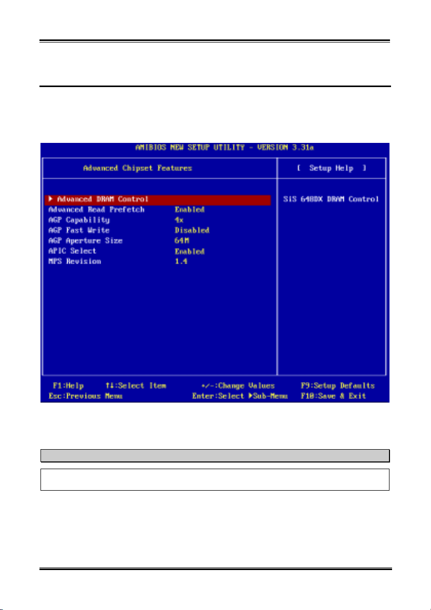
Chapter 4
4-14
4-4. Advanced Chipset Features Setup Menu
The Advanced Chipset Features Setup Menu is used to modify the contents of the buffers in the chipset
on the motherboard. Since the parameters of the buffers are closely related to hardware, if the setup is not
correct or is false, the motherboard will become unstable or you will not be able to boot up. If you don’t
know the hardware very well, use default values (i.e. use the LOAD SETUP DEFAULTS option).
Figure 4-5A. Advanced Chipset Features Setup Menu Screen Shot
You can use the arrow keys to move between the items. Use PgUP, PgDn, + or - key to change the values.
When you have finished setting up the chipset, press ESC to go back to the main menu.
Note
The parameters in this screen are for system designers, service personnel, and technically competent
users only. Do not reset these values unless you understand the consequences of your changes.
Advanced DRAM Control:
This item can let you set several items concerning the DRAM parameters. If you do not understand what
each item does, please keep the default settings. Wrong settings may cause system unstablity, data loss or
even prevent boot up!
SR7-8X
Page 63
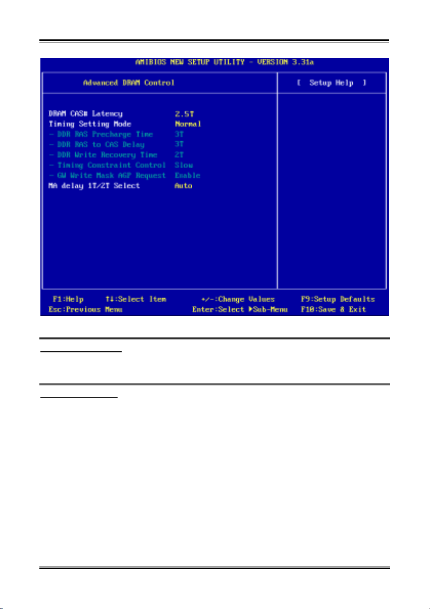
Introducing the BIOS
Figure 4-5B. Advanced DRAM Control Setup Menu Screen Shot
4-15
DRAM CAS# Latency:
Three options are available: 2T ( 2.5T ( 3T. The default setting is 2.5T. You can select SDRAM CAS
(Column Address Strobe) latency time according your SDRAM specification.
Timing Setting Mode:
Six options are available: Safe ( Normal ( Fast ( Turbo ( Ultra ( Manual. The default setting is
Normal. If you choose the Manual, the following items will be available.
DDR RAS Precharge Time:
Three options are available: 2T ( 3T ( 4T. The default setting is 3T. This item is to set SDR/DDR
SDRAM RAS precharge time. It can define the SDRAM precharge to ACT command period.
tRP timing value (Precharge time – time from precharge command to when back can be activated).
DDR RAS to CAS Delay:
Three options are available: 2T ( 3T ( 4T. The default setting is 3T. This item is to set SDR/DDR
SDRAM RAS to CAS delay. It can define the SDRAM ACT to Read/Write command period.
tRCD timing value = RAS to CAS latency + rd/wr command delay
User’s Manual
Page 64

Chapter 4
4-16
DDR Write Recovery Time:
Three options are available: 1T ( 2T ( 3T. The default setting is 2T. This item is to set SDR/DDR
SDRAM write recovery time. This item (bit) controls the number of clock cycles that must occur from
the last valid write operation to the earlist time a new Precharge command can be asserted to the same
bank. When you set it to 1T, tWR duration is 1 clock cycle, etc.
Timing Constraint Control:
Two options are available: Fast ( Normal. The default setting is Normal. Timing Constraint Control
on DDR SDRAM Back-to-Back write Commands which are issued to different ranks.
GW Write Mask AGP Request:
Two options are available: Disabled ( Enabled. The default setting is Enabled. When you set to
Enabled, a graphic window write operation will forbid AGP device to access memory until this write
operation is finished. When set to Disabled, AGP request can access memory as usual.
MA Delay 1T/2T Select:
Three options are available: Auto ( MA 2T ( MA 1T. The default setting is Auto. This item will effect
the memory address read/write speed, MA 1T will be the fast selection.
Back to Advanced Chipset Features Setup Menu Here:
Advanced Read Prefetch:
Two options are available: Disabled or Enabled. The default setting is Enabled. This item controls the
prefetch caching for PCI slave control, Select Enable will increase the system performance.
AGP Capability:
Two options are available: 4X ( 2X. The default setting is 4X. If you use the older AGP adapter that
does not support AGP 4X mode, you need to set this item to 2X. You can check your AGP adapter user’s
manual to know what kind of AGP mode it can support. If you use the 8X AGP adaptor, the item will
change to 8X ( 4X.
AGP Fast Write:
Two options are available: Disabled or Enabled. The default setting is Disabled. If your AGP adapter can
support this function, then you can choose Enabled. Otherwise, choose Disabled. Enabling this item can
improve your system performance, but it may also decrease system compatibility.
AGP Aperture Size:
Up to seven options are available: 4MB ( 8MB ( 16MB ( 32MB ( 64MB ( 128 MB ( 256 MB.
The default setting is 64MB. This option specifies the amount of system memory that can be used by the
AGP device. The aperture is a portion of the PCI memory address range dedicated for graphics memory
address space. Host cycles that hit the aperture range are forwarded to the AGP without any translation.
See http://www.agpforum.org
for AGP information.
SR7-8X
Page 65

Introducing the BIOS
4-17
APIC Select:
Two options are available: Disabled or Enabled. The default setting is Enabled. If you set to Enabled, the
next item will be available to choose. When you set it to Disabled, the system will use the default six PCI
IRQs for all devices, and will not increase the number of PCI IRQs.
MPS Revision:
This option specifies which version of MPS the motherboard will use.
Two options available: 1.1 or 1.4, The default setting is 1.4. MPS stands for Multi-Processor
Specification. If you use an older operating system for dual processor executing, please set this option to
1.1.
User’s Manual
Page 66
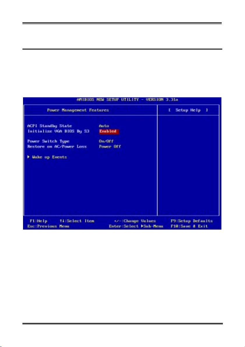
Chapter 4
4-18
4-5. Power Management Setup Menu
When the computer operates normally, it is in Normal mode. In this mode, the Power Management
Program will monitoring the access to video, I/O ports and drives, and the operating status of the
keyboard, mouse and other device. These are referred to as Power Management Events. In cases where
none of these events occur within setting time, the system enters the power saving mode. When one of the
controlled events occurs, the system immediately returns to normal mode and operates at its maximum
speed.
1. In the Main Menu, select “Power Management Setup” and press <Enter>.
Figure 4-6A. Power Management Setup Main Menu
2. You can use the arrow keys to move between the items. Use PgUP, PgDn, + or - key to change the
values. When you have finished setting up the chipset, press <Esc> to go back to the main menu.
3. After you have configured the Power Management feature, press <Esc> to go back to the Main Menu.
We are now going to briefly explain the options in this menu:
ACPI Function (Advanced Configuration and Power Interface):
ACPI gives the operating system direct control over the power management and Plug and Play functions
of a computer. The ACPI functions are always “Enabled”. If you want ACPI functions to work normally,
you should notice two things. One is your operating system must support ACPI, as of now only
Microsoft
functions. The second thing is that all devices and add-on cards in your system must fully support ACPI,
both hardware and software (drivers). If you want to know if your devices or add-on cards support
SR7-8X
®
Windows® 98 SE, Windows® 2000, Windows® ME and Windows® XP supports these
Page 67

Introducing the BIOS
ACPI or not, please contact the device or add-on card manufacture for more information. If you want to
know more about ACPI specifications, please go to the address below for more detailed information:
http://www.teleport.com/~acpi/acpihtml/home.htm
ACPI requires an ACPI-aware operating system. ACPI features include:
! Plug and Play (including bus and device enumeration) and APM functionality normally contained in
the BIOS.
! Power management control of individual devices, add-in cards (some add-in cards may require an
ACPI-aware driver), video displays, and hard disk drives.
! A Soft-off feature that enables the operating system to power off the computer.
! Support for multiple wake-up events (see Table 4-5-1).
! Support for a front panel power and sleep mode switch. Table 4-5-2 describes the system states based
on how long the power switch is pressed, depending on how ACPI is configured with an ACPI-aware
operating system.
4-19
System States and Power States
Under ACPI, the operating system directs all system and device power state transitions. The operating
system puts devices in and out of low-power states based on user preferences and knowledge of how
devices are being used by applications. Devices that are not being used can be turned off. The operating
system uses information from applications and user settings to put the system as a whole into a low-power
state.
The table below describes which devices or specific events can wake the computer from specific states.
Table 4-5-1: Wake Up Device and Events
These device/events can wake up the
computer……
Power switch Sleeping mode or power off mode
RTC alarm Sleeping mode or power off mode
LAN Sleeping mode or power off mode
Modem Sleeping mode or power off mode
USB Sleeping mode
PS/2 keyboard Sleeping mode
PS/2 mouse Sleeping mode
Table 4-5-2: Effect of Pressing the Power Switch
If the system is in this
state……
Off Less than four seconds Power on
On More than four seconds Forced power off
On Less than four seconds Defined by OS
Sleep Less than four seconds Wake up
ACPI Standby State:
Three options are available: S1 ( S3 ( Auto. The default setting is S1. In this case, BIOS will
automatically judge your system can running on which state. Generally, ACPI has six states: System S0
state, S1 state, S2 state, S3 state, S4 state, S5 state. S1 and S3 states are described below:
User’s Manual
……and the power switch is
pressed for
……from this state
……the system enters this
state
Page 68

Chapter 4
4-20
The S1 (POS) State (POS means Power On Suspend):
While the system is in the S1 sleeping state, its behavior is as described below:
! The processor is not executing instructions. The processor’s complex context is maintained.
! Dynamic RAM context is maintained.
! Power Resources are in a state compatible with the system S1 state. All Power Resources that supply a
System Level reference of S0 are in the OFF state.
! Devices states are compatible with the current Power Resource states. Only devices which solely
reference Power Resources which are in the ON state for a given device state can be in that device state.
In all other cases, the device is in the D3 (off) state.
! Devices that are enabled to wake the system and that can do so from their current device state can
initiate a hardware event which transitions the system state to S0. This transition causes the processor
to continue execution where it left off.
To transition into the S1 state, the operating software does not have to flush the processor's cache.
The S3 (STR) State (STR means Suspend to RAM):
The S3 state is logically lower then the S2 state and is assumed to conserve more power. The behavior of
this state is defined as follows:
! Processor is not executing instructions. The processor complex context is not maintained.
! Dynamic RAM context is maintained.
! Power Resources are in a state compatible with the system S3 state. All Power Resources that supply a
System Level reference of S0, S1, or S2 are in the OFF state.
! Devices states are compatible with the current Power Resource states. Only devices which solely
reference Power Resources which are in the ON state for a given device state can be in that device state.
In all other cases, the device is in the D3 (off) state.
! Devices that are enabled to wake the system and that can do so from their current device state can
initiate a hardware event which transitions the system state to S0. This transition causes the processor
to begin execution at its boot location. The BIOS performs initialization of core functions as required to
exit an S3 state and passes control to the firmware resume vector. Please see the ACPI Specification
Rev. 1.0 book section 9.3.2 for more details on BIOS initialization.
From the software point of view, this state is functionally the same as the S2 state. The operational
difference can be that some Power Resources that could be left ON in the S2 state might not be available
to the S3 state. As such, additional devices can be required to be in logically lower D0, D1, D2, or D3
state for S3 than S2. Similarly, some device wake events can function in S2 but not S3.
Because the processor context can be lost while in the S3 state, the transition to the S3 state requires that
the operating software flush all dirty cache to DRAM.
Above information for system S1 were refer to ACPI Specification Rev. 1.0.
+
Initialize VGA BIOS By S3:
Two options are available: Disabled or Enabled. The default setting is Enabled. This item allow you
choose when system wake up from S3 state, then system will initialize VGA BIOS or not. Because some
VGA card needs to do this action, then after wake up, the display screen can back to normal.
SR7-8X
Page 69
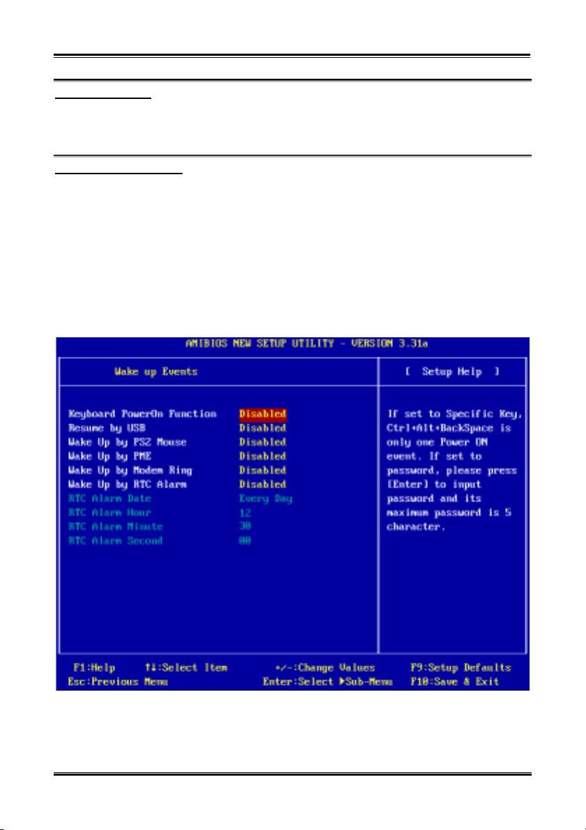
Introducing the BIOS
4-21
Power Switch Type:
Two options are available: On/Off or Suspend. The default setting is On/Off. This item allow you choose
the functions for power button. Select On/Off for power on and power off the computer system. Select
Suspend for suspending the computer system.
Restore on AC/Power loss:
Three options are available: Power Off ( Power On ( Last State. The default setting is Power Off. This
item lets you sett the system power state when power recovers. If you set it to Power Off, when power
returns, whatever state your computer was in before the power failure, the system will always turn off. If
you set it to Power On, when power returns, whatever state your computer was in before the power
failure, the system will always turn on. If you set it to Last State, when the power returns, the computer
return to the previous power state.
Wake Up Events:
The following is a list of the events. When an I/O device wants to gain the attention of the operating
system, it causes an event to occur. If any of these Enabled event occues, the system will be waking up to
perform the task.
Figure 4-6B. PM Wake Up Events Screen Shot
User’s Manual
Page 70

Chapter 4
4-22
Keyboard PowerOn Function:
Four options are available: Disabled ( Any Key ( Specific Key ( Password. The default setting is
Disabled. This item let you set the key for keypad wakeup. After you set the key or password, any event
affecting keypad will awaken a system that has powered down.
Resume by USB:
Two options are available: Disabled or Enabled. The default setting is Disabled. When set to Enabled,
any event occurring at a USB port will awaken a system that has powered down.
Wake Up by PS2 Mouse:
Two options are available: Disabled or Enabled. The default setting is Disabled. When set to Enabled,
any event affecting PS/2 mouse (through the PCI PME internal pin) will awaken a system that has
powered down.
Wake Up by PME:
Two options are available: Disabled or Enabled. The default setting is Disabled. When set to Enabled,
any event affecting LAN card (through the PCI PME internal pin) will awaken a system that has powered
down.
Wake Up by Modem Ring:
Two options are available: Disabled or Enabled. The default setting is Disabled. When set to Enabled,
any event affecting the modem (external modem) ring will awaken a system that has powered down.
Wake Up by RTC Alarm:
Two options are available: Disabled or Enabled. The default setting is Disabled. When set to Enabled,
you can set the date, hour, minute and second alarm at which the RTC (real-time clock) alarm awakens
the system from Suspend mode. The enable items will appear white in color and disabled items will show
a blue green color.
RTC Alarm Date:
You can select the date from 01 ~ 31, or Every Day. The default setting is Everyday. This field is not
available to enter when the “Resume by RTC Alarm” field is Disabled.
RTC Alarm Hour:
You can select the hour from 00 ~ 23, which means the hour of 00 to hour of 24. This field is not
available to enter when the “Resume by RTC Alarm” field is set to Disabled.
RTC Alarm Minute:
You can select the minute from 00 ~ 59, which means the minute of 00 to minute of 60. This field is
not available to enter when the “Resume by RTC Alarm” field is set to Disabled.
RTC Alarm Second:
You can select the second from 00 ~ 59, which means the second of 00 to second of 60. This field is
not available to enter when the “Resume by RTC Alarm” field is set to Disabled.
SR7-8X
Page 71
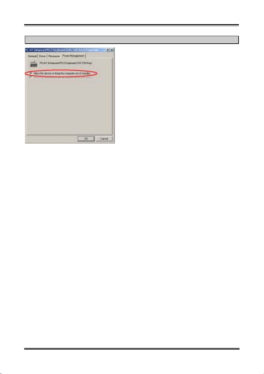
Introducing the BIOS
Note
If your operation system is Windows® 2000 or Windows®
XP, and you want to wake up the system from the S1, S3
or S4 state use the keyboard, mouse, USB device or LAN
device. Please go to the “Device Manager”, then choose
the device item and find the item “, Allow this device to
bring the computer out of standby”, then check it on the
check box. The wake up function will work normally.
4-23
User’s Manual
Page 72
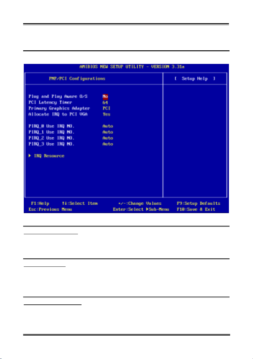
Chapter 4
4-24
4-6. PnP/PCI Configurations Setup Menu
In this menu, you can change the INT# and IRQ# of the PCI bus and other hardware settings.
Figure 4-7A. PnP/PCI Configurations Setup Menu Screen Shot
Plug and Play Aware O/S:
Two options are available: No or Yes. The default setting is No. This item allows you to choose the job of
initialize the PnP devices is done by BIOS or OS. If you choose Yes, the operating system will initialize
the PnP devices and give them a proper resources.
PCI Latency Timer:
Eight options are available: 32 ( 64 ( 96 ( 128 ( 160 ( 192 ( 224 ( 248. The default setting is
64. This item allows you to set the PCI latency delay time. Generally, the default will meet all requires for
PCI cards. But some special PCI card may need the special PCI latency delay time, then can work
normally. In this case, please change the delay time to meet the PCI card requirement.
Primary Graphics Adapter:
Two options are available: PCI or AGP. The default setting is PCI. When you install more than one
display card, you can choose either a PCI display card or an AGP display card to display the boot-up
screen. If you have only installed one display card, the BIOS will detect which slot (AGP or PCI) you
installed it, and everything will be taken care of by the BIOS.
SR7-8X
Page 73
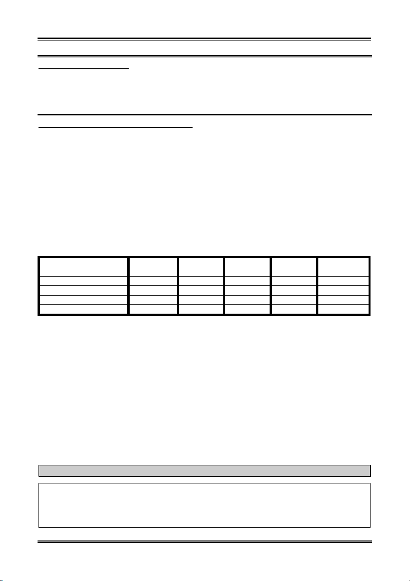
Introducing the BIOS
4-25
Allocate IRQ to PCI VGA:
Two options are available: Yes or No. The default setting is Yes. Name the interrupt request (IRQ) line
assigned to the VGA on your system. Activity of the selected IRQ always awakens the system.
You can assign an IRQ for the either PCI VGA or disable it.
PIRQ_0 Use IRQ No. ~ PIRQ_3 Use IRQ No.:
Seven options are available: Auto ( 3 ( 4 ( 5 ( 7 ( 10 ( 11. Default setting is Auto. This item
allows the system to automatically specify the IRQ number for the device installed on PCI slots. This
means that the system can specify the fixed IRQ number for the device installed on the PCI slots (PCI slot
1 to PCI slot 5). This is a useful function for when you want to fix the IRQ for a specific device.
For example, if you want to move your hard disk to another computer and don’t want to re-install
Windows
®
NT or Windows® 2000, you can simply specify the IRQ for the device installed on the new
computer to fit the original computer settings.
This feature is for the operating system that will record and fix the PCI configuration status if you want to
change it.
For the relations between the hardware layout of PIRQ (the signals from the SiS 963chipset), INT#
(means PCI slot IRQ signals) and devices, please refer to the table below:
SIGNALS
PIRQ_0 Assignment
PIRQ_1 Assignment
PIRQ_2 Assignment
PIRQ_3 Assignment
PCI
Slot 1
INT A INT B INT B INT D INT C
INT B INT D INT A INT A INT D
INT C INT C INT D INT B INT A
INT D INT A INT C INT C INT B
PCI
Slot 2
PCI
Slot 3
PCI
Slot 4
PCI
Slot 5
! USB used INT D.
! Each PCI slot has four INT#s (INT A~INT D), and the AGP slot has two INT# (INTA and INT B).
Note
! PCI slot 1 shares IRQ signals with the AGP slot.
! If you want to install two PCI cards into those PCI slots that share IRQ with one another at the
same time, you must make sure that your OS and PCI devices’ driver supports the IRQ sharing
function.
User’s Manual
Page 74
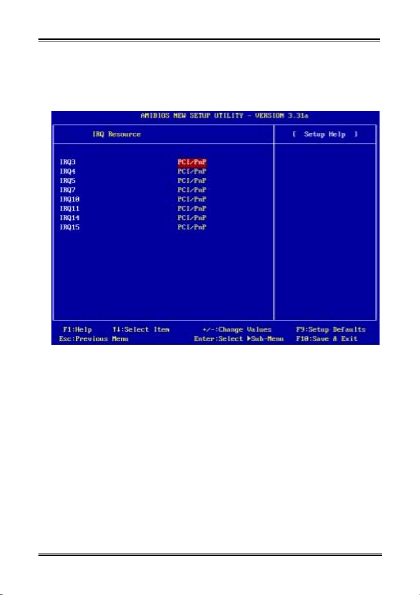
Chapter 4
4-26
IRQ Resources:
Two options are available: PCI/PnP or Reserve. The default setting is PCI/PnP. If you have trouble in
assigning the interrupt resources automatically, you can choose Reserve to set which IRQ should be
reserved. See the screen shot below.
SR7-8X
Figure 4-7B. IRQ Resource Setup Menu Screen Shot
Page 75
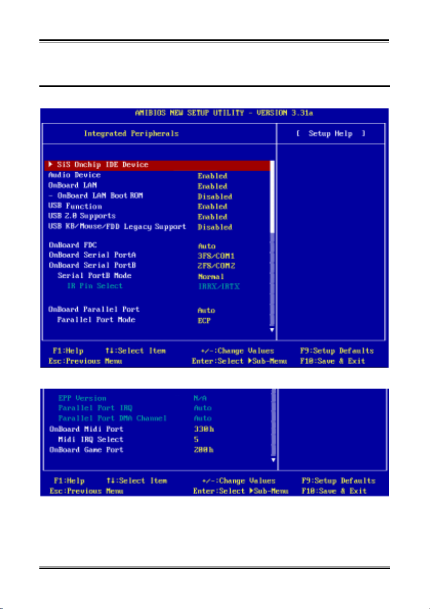
Introducing the BIOS
4-27
4-7. Integrated Peripherals
In this menu, you can change the onboard I/O device, I/O port address and other hardware settings.
Figure 4-8A. Integrated Peripherals Setup Menu Upper Screen Shot
Figure 4-8B. Integrated Peripherals Setup Menu Lower Screen Shot
User’s Manual
Page 76
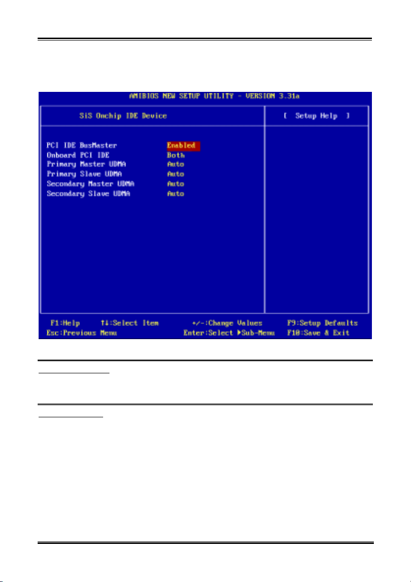
Chapter 4
4-28
SiS Onchip IDE Device:
This item can let you sets several items concerning the SiS onchip IDE device parameters.
Figure 4-8C. SiS Onchip IDE Device Setup Menu Screen Shot
PCI IDE BusMaster:
Two options are available: Disabled or Enabled. The default setting is Enabled. The onboard IDE
controller can be set as enable or disable.
Onboard PCI IDE:
Four options are available: Disabled ( Primary ( Secondary ( Both. Default setting is Both. This item
allows you disable all onboard PCI IDE devices, or enable one of them. Of course you can enable both
PCI IDE devices as well. The enabled items will appear white in color and disabled items will show in a
blue green color.
Primary Master UDMA:
Two options are available: Auto or Disabled. The default setting is Auto. Ultra DMA is a DMA data
transfer protocol that utilizes ATA commands and the ATA bus to allow DMA commands to transfer
data at a maximum burst rate of 133 MB/sec.
® Auto: When you select Auto, the system automatically determines the optimal data transfer
SR7-8X
rate for each IDE device. (Default)
Page 77

Introducing the BIOS
4-29
® Disabled: If you encounter the problem of using Ultra DMA devices, you can try to set this item
Primary Slave UDMA:
Two options are available: Auto or Disabled. The default setting is Auto. Ultra DMA is a DMA data
transfer protocol that utilizes ATA commands and the ATA bus to allow DMA commands to transfer
data at a maximum burst rate of 133 MB/sec.
® Auto: When you select Auto, the system automatically determines the optimal data transfer
® Disabled: If you encounter the problem of using Ultra DMA devices, you can try to set this item
Secondary Master UDMA:
Two options are available: Auto or Disabled. The default setting is Auto. Ultra DMA is a DMA data
transfer protocol that utilizes ATA commands and the ATA bus to allow DMA commands to transfer
data at a maximum burst rate of 133 MB/sec.
® Auto: When you select Auto, the system automatically determines the optimal data transfer
® Disabled: If you encounter the problem of using Ultra DMA devices, you can try to set this item
Secondary Slave UDMA:
Two options are available: Auto or Disabled. The default setting is Auto. Ultra DMA is a DMA data
transfer protocol that utilizes ATA commands and the ATA bus to allow DMA commands to transfer
data at a maximum burst rate of 133 MB/sec.
® Auto: When you select Auto, the system automatically determines the optimal data transfer
® Disabled: If you encounter the problem of using Ultra DMA devices, you can try to set this item
to Disabled.
rate for each IDE device. (Default)
to Disabled.
rate for each IDE device. (Default)
to Disabled.
rate for each IDE device. (Default)
to Disabled.
Back to Integrated Peripherals Setup Menu Here:
Audio Device:
Two options are available: Disabled or Enabled. The default setting is Enabled. This item allows you to
enable or disable the onboard audio controller.
OnBoard LAN:
Two options are available: Disabled or Enabled. The default setting is Enabled. This item allows you to
enable or disable the onboard LAN controller.
OnBoard LAN Boot ROM
Two options are available: Enabled or Disabled. The default setting is Disabled. When you set to
Enabled, even you do not connect bootable devices on your computer system, the system will
searching the bootable file through the local network. If system fined the bootable file on local
network, it will load it and use it to boot your computer system.
User’s Manual
Page 78

Chapter 4
4-30
USB Function:
Two options are available: Disabled ( Enabled. The default setting is Enabled. This should be enabled if
your system has a USB device installed on the system board and you wish to use it. If you add a higher
performance controller, you will need to disable this feature.
USB 2.0 Supports:
Two options are available: Disabled ( Enabled. The default setting is Enabled. If you have connecting
the USB 2.0 device onto your motherboard and using the onboard USB ports. Please set this item to
Enabled.
USB KB/Mouse/FDD Legacy Support:
Two options are available: Disabled ( Enabled. The default setting is Disabled. If your operating system
supports a USB device natively, please set it to Disabled. Only in some situations, such as in a pure DOS
environment that does not support a USB legacy device, should you set it in Enabled. What’s the USB
legacy device? For example: USB floppy, USB keyboard and USB mouse, etc.
OnBoard FDC:
Three options are available: Auto ( Disabled ( Enabled. The default setting is Auto. This is used to
enable or disable the onboard FDD Controller. If you add a higher performance controller, you will need
to disable this feature.
Onboard Serial PortA:
Five options are available: Disabled ( 3F8/COM1 ( 2F8/COM2 ( 3E8/COM3 ( 2E8/COM4. The
default setting is 3F8/COM1. This item allows you to determine which I/O address the onboard serial
portA controller will access.
Onboard Serial PortB:
Five options are available: Disabled ( 3F8/COM1 ( 2F8/COM2 ( 3E8/COM3 ( 2E8/COM4. The
default setting is 2F8/COM2. This item allows you to determine which I/O address the onboard serial
portB controller will access.
Serial PortB Mode:
Four options are available: Normal ( 1.6 us ( 3/16 Baud ( ASKIR. The default setting is Normal.
When you select the item Normal, then the following item will not appear.
IR Pin Select:
Two options are available: SINB/SOUTB or IRRX/IRTX. The default setting is IRRX/IRTX. If you
choose IRRX/IRTX, your motherboard must support a COM port IR KIT connection. Otherwise, you
can only choose the SINB/SOUTB to use the IR header on your motherboard to connect your IR KIT.
Please use the default setting.
Onboard Parallel Port:
Five options are available: Auto ( Disabled ( 378h ( 278h ( 3BCh. The default setting is Auto.
Select a logical LPT port name and matching address for the physical parallel (printer) port.
SR7-8X
Page 79

Introducing the BIOS
Parallel Port Mode:
Five options are available: Normal ( SPP ( EPP ( ECP ( ECP/EPP. Default is ECP mode.
Select an operating mode for the onboard parallel (printer) port. SPP (Standard Parallel Port), EPP
(Extended Parallel Port), ECP (Extended Capabilities Port) or ECP/EPP.
Select SPP unless you are certain your hardware and software supports both EPP or ECP mode.
According to your selection, the following items will available.
EPP Version:
Two options are available: EPP 1.9 or EPP 1.7. The default setting is EPP1.9. When the mode
selected for the parallel port mode is EPP, the two EPP mode options are available.
Parallel Port IRQ:
Two options are available: 5 or 7.
Parallel Port DMA Channel:
Three options are available: 0 ( 1 ( 3. The default setting is 3.
The table below will show you the relationship between different Parallel Port Mode and its following
three items.
4-31
Items Normal SPP EPP ECP ECP/EPP
EPP Version
Parallel Port
IRQ
Parallel Port
DMA Channel
OnBoard Midi Port:
Five options are available: Disabled ( 330h ( 300h ( 290h ( 292h. Default is 330h. This item allows
you to choose the onboard Midi port address.
Midi IRQ Select:
Three options are available: 5 ( 10 ( 11. The default setting is 5. This item allows you to choose
the Midi port IRQ.
OnBoard Game Port:
Three options are available: Disabled ( 200h ( 208h. The default setting is 200h. This item allows you
to choose the onboard game port address.
N/A N/A EPP 1.9
or EPP 1.7
Auto Auto Auto Auto Auto
N/A N/A N/A Auto Auto
N/A EPP 1.9
or EPP 1.7
User’s Manual
Page 80
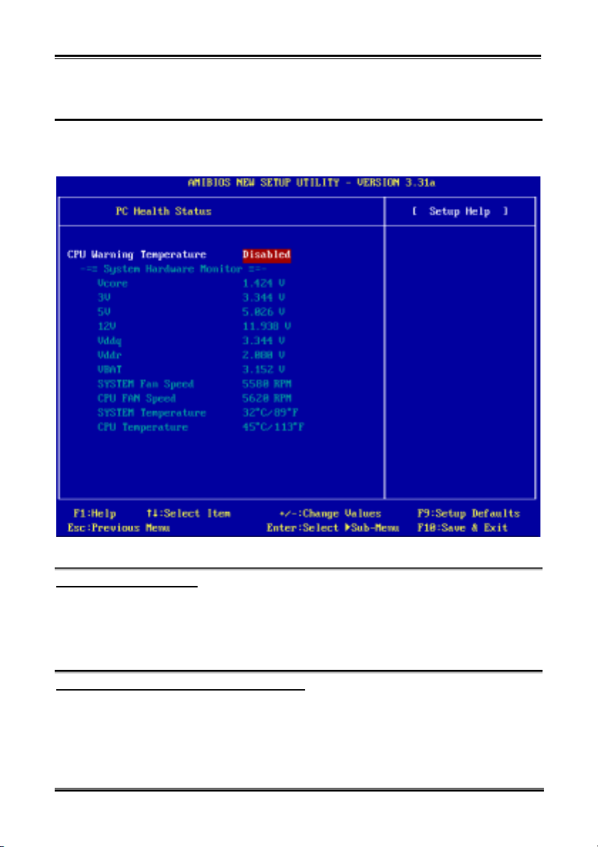
Chapter 4
4-32
4-8. PC Health Status
You can set the warning and shutdown temperatures for your computer system, and you can check the fan
speeds and power supply voltages of your computer system. The features are useful for monitoring all the
important parameters within your computer system. We call it the PC Health Status.
Figure 3-9. PC Health Status Setup Menu Screen Shot
CPU Warning Temperature:
The values of CPU Warning Temperature from 45 to 75 are available. The default setting is Disabled.
You can set the processor warning temperature in two ways. One is Press +/- keys to modify the value of
the processor warning temperature. The other way is you can use numeric keys to set the value directly
and press the <Enter> key to confirm. If the processor temperature exceeds the settings value, the system
will give you an alarm message or sound to remind you that the processor is overheating.
All Voltages, Fans Speed and Thermal Monitoring:
These items list the current states of the processor and environment (using RT1 to detect them.)
temperatures as well as fan speeds (processor fan and chassis fan). It cann’t be changed by the user.
The following items list the voltage states of the system power. It is also unchangeable.
SR7-8X
Page 81

Introducing the BIOS
Note
The hardware monitoring features for temperatures, fans and voltages will occupy the I/O address
from 294H to 297H. If you have a network adapter, sound card or other add-on cards that might use
those I/O addresses, please adjust your add-on card I/O address, to avoid the use of those addresses.
4-33
4-9. Set Password
Set Password: Can let you enter and change the options of the setup menus. When you select this
Type the password, up to eight characters in length, and press <Enter>. The password typed now will
clear any previously entered password from CMOS memory. You will be asked to confirm the password.
Type the password again and press <Enter>. You may also press <Esc> to abort the selection and not
enter a password.
To disable a password, just press <Enter> when you are prompted to enter the password. A message will
confirm the password will be disabled. Once the password is disabled, the system will boot and you can
enter Setup freely.
When a password has been enabled, you will be prompted to enter it every time you try to enter Setup.
This prevents an unauthorized person from changing any part of your system configuration. Additionally,
when a password is enabled, you can also require the BIOS to request a password every time your system
is rebooted. This would prevent unauthorized use of your computer. You determine when the password is
required within the “Advanced BIOS Features Setup Menu” and its “Password Check”. If the Security
option is set to Always, the password will be required both at boot and at entry to Setup. If you set to
Setup, prompting only occurs when trying to enter Setup.
function, the following message will appear at the center of the screen to assist you in
creating a password.
Enter new password:
Password disabled.
4-10. Load Optimized Defaults
When you press <Enter> on this item you get a confirmation dialog box with a message similar to:
[Load optimized settings]
Pressing <Enter> loads the default values that are factory settings for optimal performance system
operations, or you can press <Esc> to abort.
User’s Manual
Page 82

Chapter 4
4-34
4-11. Load Fail Safe Defaults
When you press <Enter> on this item you get a confirmation dialog box with a message similar to:
[Load fail safe settings]
Pressing <Enter> loads the BIOS default values for the most stable, minimal-performance system
operations, or you can press <Esc> to abort.
4-12. Load Original Values
When you press <Enter> on this item you get a confirmation dialog box with a message similar to:
[Load setup original values]
Pressing <Enter> loads the BIOS default values for the most stable, minimal-performance system
operations, or you can press <Esc> to abort.
4-13. Save & Exit Setup
Pressing <Enter> on this item asks for confirmation:
[Save current settings and exit]
Pressing <Enter> stores the selections made in the menus in CMOS - a special section of memory that
stays on after you turn your system off. The next time you boot your computer, the BIOS configures your
system according to the Setup selections stored in CMOS. After saving the values the system is restarted
again.
4-14. Exit Without Saving
Pressing <Enter> on this item asks for confirmation:
[Quit without saving changes]
This allows you to exit Setup without storing in CMOS any change. The previous selections remain in
effect. This exits the Setup utility and restarts your computer.
SR7-8X
Page 83
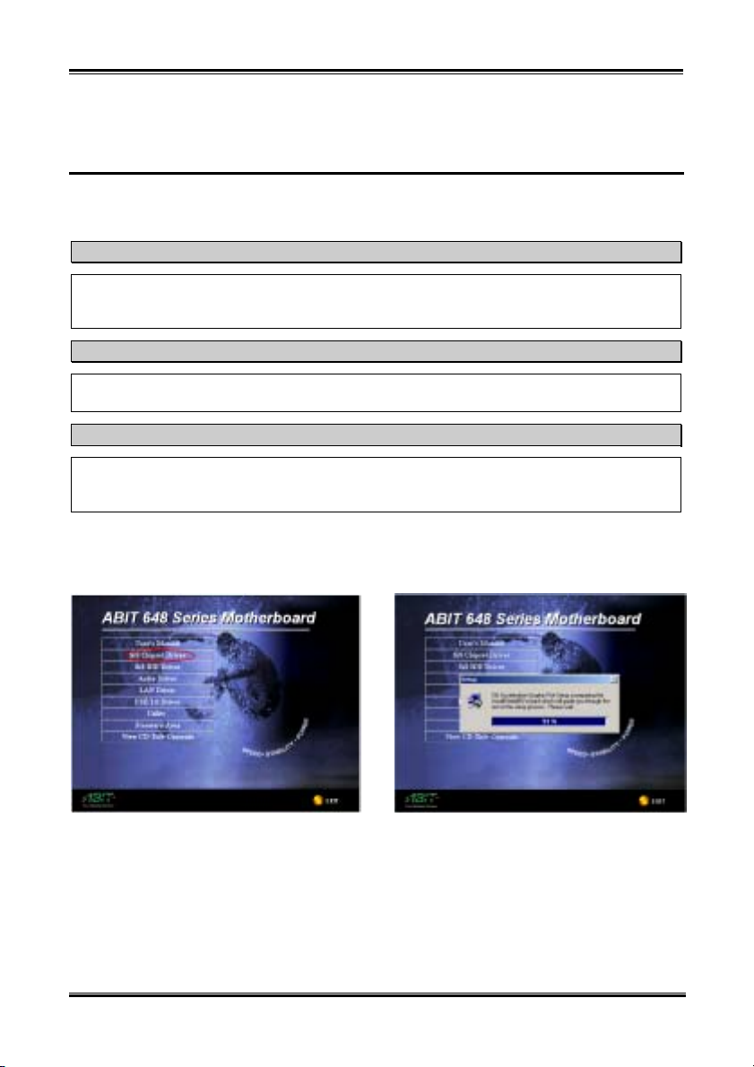
SiS Chipset Drivers Installation for Windows® 2000
A-1
Appendix A. SiS Chipset Drivers Installation for
Windows
After you’ve installed Windows® 2000, you will need to install the SiS chipset drivers. Step by step
instructions on how to do this are found in the following section.
After installing Windows® 2000, the quality of your display will be poor because it will be set to
640*480 and 16 colors. For the best screen capture quality, install the VGA drivers and set the desktop
to 800*600 using True Color.
Under Windows® 2000 operating system you have to install the service pack 2 (SP2) or latest service
pack to get the best system performance. You can download SP2 at Microsoft® WEB site.
Details of the Windows® 2000 operating system will not be mentioned in this manual. If you have any
problems with Windows® 2000 installation, operation, or settings, please refer to your Windows®
2000 user's manual or other databases provided by Microsoft® Corporation.
Insert the 648 series CD into your CD-ROM drive and it should execute the program automatically. If not,
you can go to the CD location and execute the execution file at the main directory of the CD. After it has
been executed you will see the screen below.
®
2000
Note
Note
Note
Step 1: Move the cursor to “SiS Chipset
Driver” and click on it. You will go to the next
screen.
User’s Manual
Step 2: The SiS AGP driver setup InstallShield
wizard shows up, and it will go to the next screen
for a while.
®
Page 84
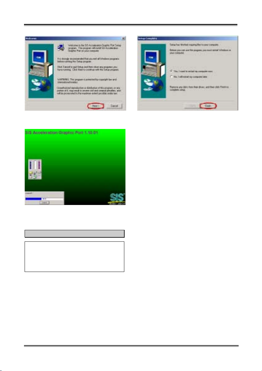
Appendix A
A-2
Step 3: You will now see the welcome screen
and its dialogue box. Click “Next>” to go on.
Step 4: The program will start to install drivers
the system needs. The installer will show the
install progress percentage.
Note
The version you see may differ, because we
may change the drivers or change the CD
version. If this happens, the version may be
different with this picture, but the install
process won’t change at all.
Step 5: When the installation is complete, the
installer will ask you to restart your computer.
We suggest that you choose “Yes, I want to
restart my computer now.” then click the
“Finish” button to restart your computer to finish
the driver updates.
SR7-8X
Page 85
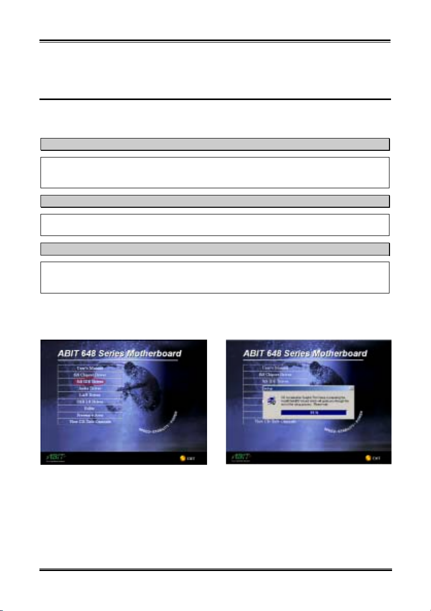
SiS IDE Drivers Installation for Windows® 2000
B-1
Appendix B. SiS IDE Drivers Installation for
Windows
After you’ve installed Windows® 2000, you will need to install the SiS IDE drivers. Step by step
instructions on how to do this are found in the following section.
After installing Windows® 2000, the quality of your display will be poor because it will be set to
640*480 and 16 colors. For the best screen capture quality, install the VGA drivers and set the desktop
to 800*600 using True Color.
Under Windows® 2000 operating system you have to install the service pack 2 (SP2) or latest service
pack to get the best system performance. You can download SP2 at Microsoft® WEB site.
Details of the Windows® 2000 operating system will not be mentioned in this manual. If you have any
problems with Windows® 2000 installation, operation, or settings, please refer to your Windows®
2000 user's manual or other databases provided by Microsoft® Corporation.
Insert the 648 series CD into your CD-ROM drive and it should execute the program automatically. If not,
you can go to the CD location and execute the execution file at the main directory of the CD. After it has
been executed you will see the screen below.
®
2000
Note
Note
Note
Step 1: Move the cursor to “SiS IDE Driver”
and click on it. You will go to the next screen.
User’s Manual
Step 2: The SiS IDE driver setup InstallShield
wizard shows up, and it will go to the next screen
for a while.
®
Page 86
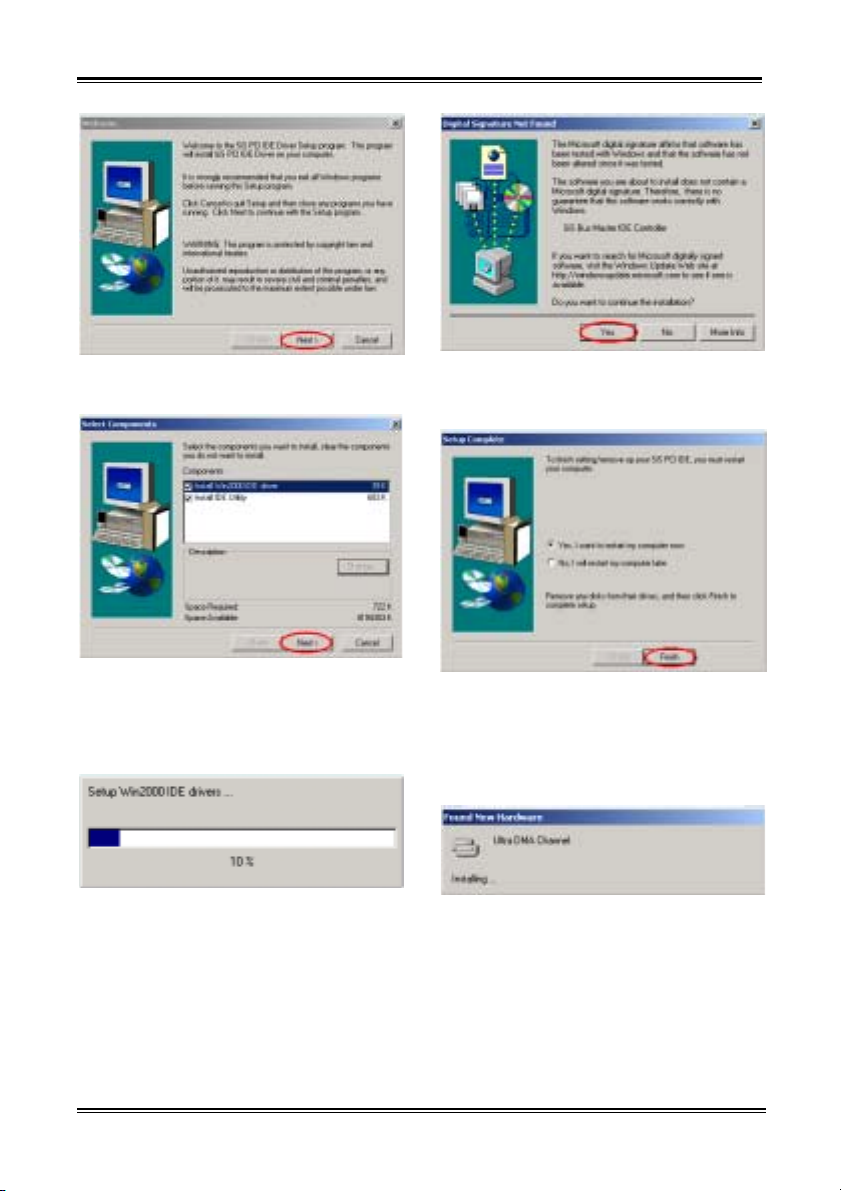
Appendix B
B-2
Step 3: You will now see the welcome screen
and its dialogue box. Click “Next>” to go on.
Step 4: This setup program will ask you to select
the components you want to install. Please check
which drivers you want to install. When you
choose the items, please click the “Next>” button
to continue.
Step 5: The installer will show the install
progress percentage.
Step 6: The “Digital Signature Not Found”
menu show up. Click “Yes” to go on. This screen
will show up again, please click “Yes” to go on.
Step 7: When the installation is complete, the
installer will ask you to restart your computer.
We suggest that you choose “Yes, I want to
restart my computer now.” then click the
“Finish” button to restart your computer to finish
the driver updates.
Step 8: When your computer system restarts,
Windows
®
2000 starts the update process and
new hardware device will be found.
SR7-8X
Page 87
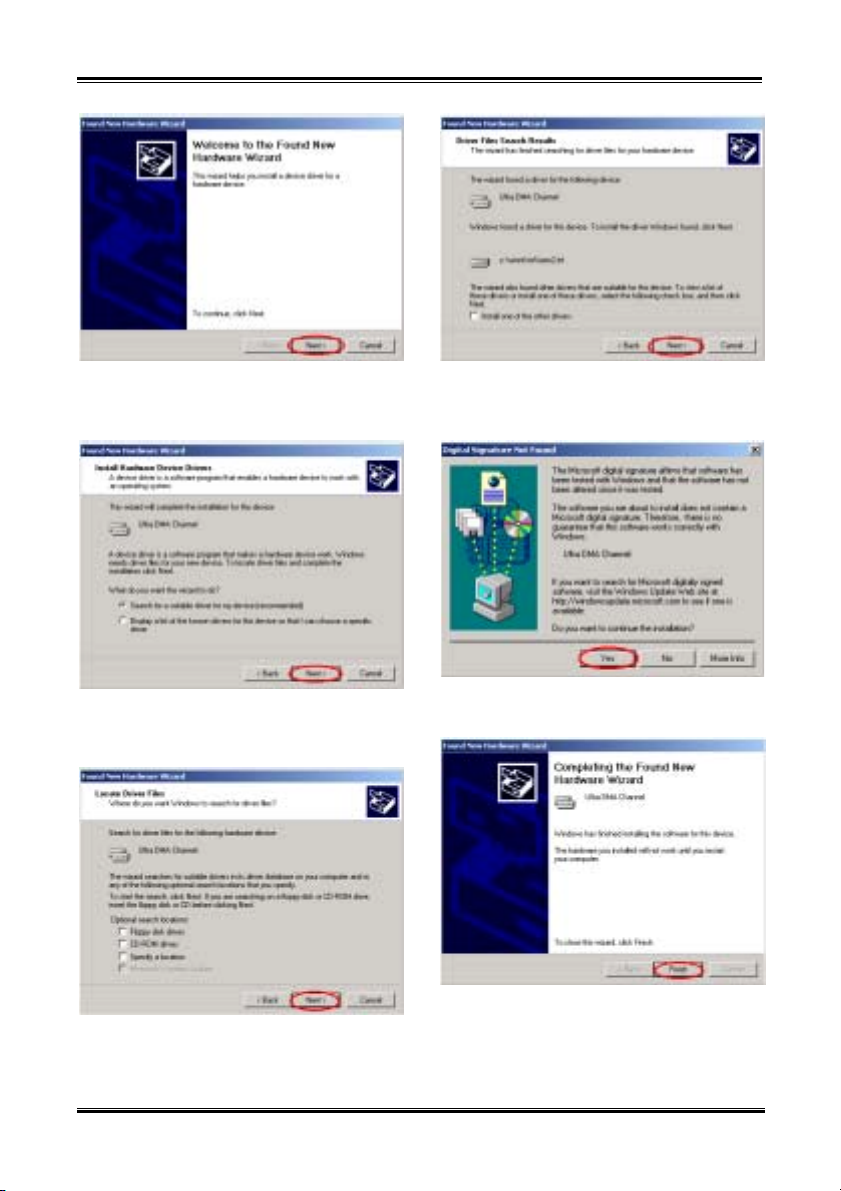
SiS IDE Drivers Installation for Windows® 2000
B-3
Step 9: You will now see the welcome screen
and its dialogue box. Click “Next>” button to go
on.
Step 10: Choose “ Search for a suitable driver
for my decice (recommended)” and click
“Next>” button to go on.
Step 12: After searching, program will fine Ultra
DMA Channel device driver and tell you where it
located. Click “Next>” button to go on.
Step 13: The “Digital Signature Not Found”
screen show up, click “Yes” to go on.
Step 14: When completing the upgrade device
Step 11: You can choose the file locate in which
drivers, here we do not need to choose anything.
Click “Next>” button to go on.
User’s Manual
driver, then click “Finish” button to go on.
Page 88
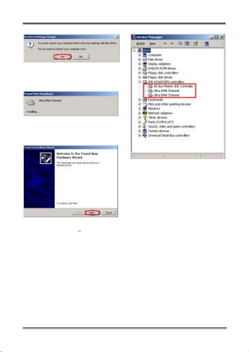
Appendix B
B-4
Step 15: “System Settings Change” dialogue
show up, click the “Yes” button to restart your
computer to finish the driver updates. Or you can
choose “No” then go to next step.
Step 16: When your computer system restarts (or
when you choose “No” to go on), Windows
®
2000 starts the update process and new hardware
device will be found.
Step 16: You will now see the welcome screen
and its dialogue box. Click “N
ext>” button to go
on.
The procedure will go through from Step 9 to
Step 15 again. After you restart the system again,
you can go to next step.
Step 16: When Windows
®
2000 restart, you can
then check the “Device Manager” to see that the
devices are properly installed.
SR7-8X
Page 89
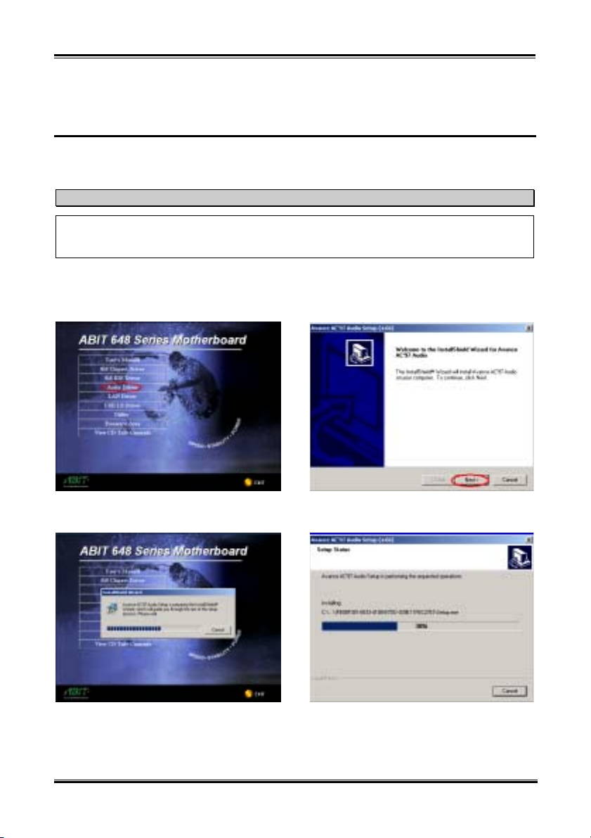
Audio Drivers Installation for Windows® 2000
C-1
Appendix C. Audio Drivers Installation for Windows®
2000
After you’ve installed SiS chipset and IDE drivers, you will need to install the audio drivers. Step by step
instructions on how to do this are found in the following section.
Note
Details of the Windows® 2000 operating system will not be mentioned in this manual. If you have any
problems with Windows® 2000 installation, operations, or settings, please refer to your Windows®
2000 user's manual or other databases provided by Microsoft® Corporation.
Insert the 648 series CD into your CD-ROM drive, and it should execute the program automatically. If
not, you can go to the CD location and execute the execution file at the main directory of the CD. After it
has been executed you will see the screen below.
Step 1: Move the cursor to “Audio Driver” and
click on it. You will go to the next screen.
Step 2: The Avance AC97 Audio setup
InstallShield
the next screen for a while.
User’s Manual
®
wizard shows up, and it will go to
Step 3: You will now see the welcome screen
and its dialogue box. Click “Next>” to go on.
Step 4: The installer will show the install status.
Page 90
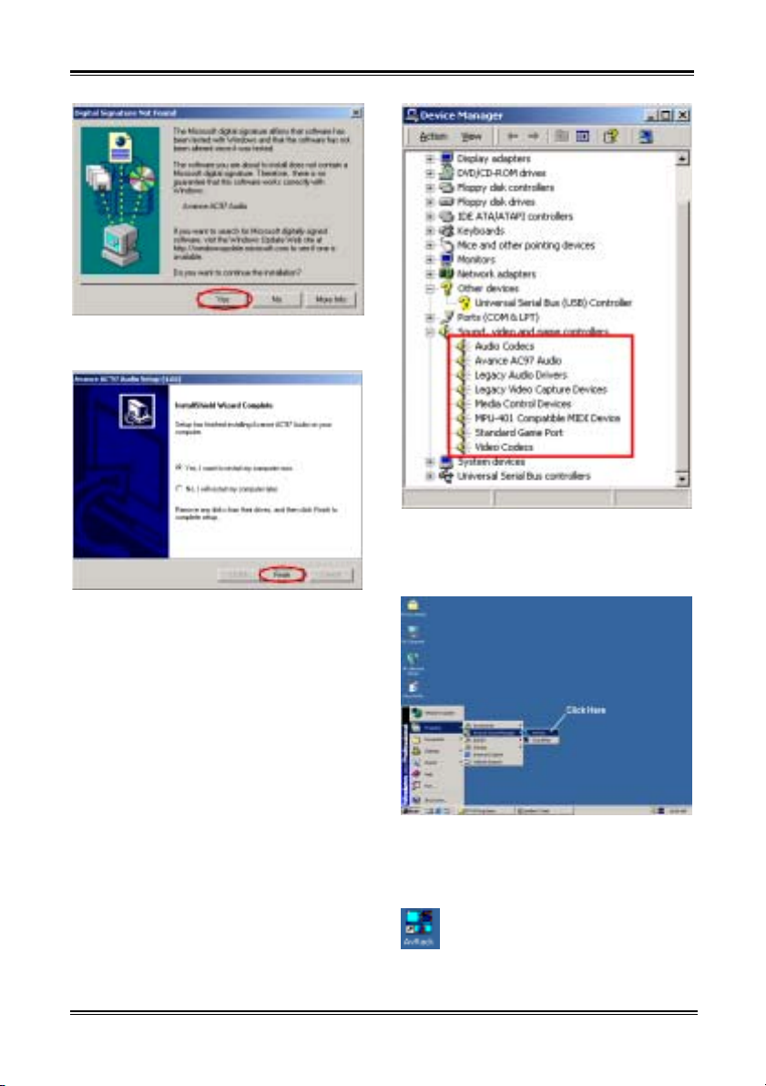
C-2
Appendix C
Step 5: The “Digital Signature Not Found”
screen show up, click “Yes” to go on.
Step 7: When system restarts and enters the
operating system, you can then check the
“Device Manager” to see that the devices are
properly installed.
Step 6: When the installation is complete, the
installer will ask you to restart your computer.
We suggest that you choose “Yes, I want to
restart my computer now.” then click the
“Finish” button to restart your computer to finish
the driver updates.
SR7-8X
Step 8: You can choose from “Start”,
“Programs” then from item “Avance Sound
Manager” ( “AvRack” to starting the
applications program. You can quickly start the
mixer panel by double click on the AvRack icon
on the desktop.
Page 91
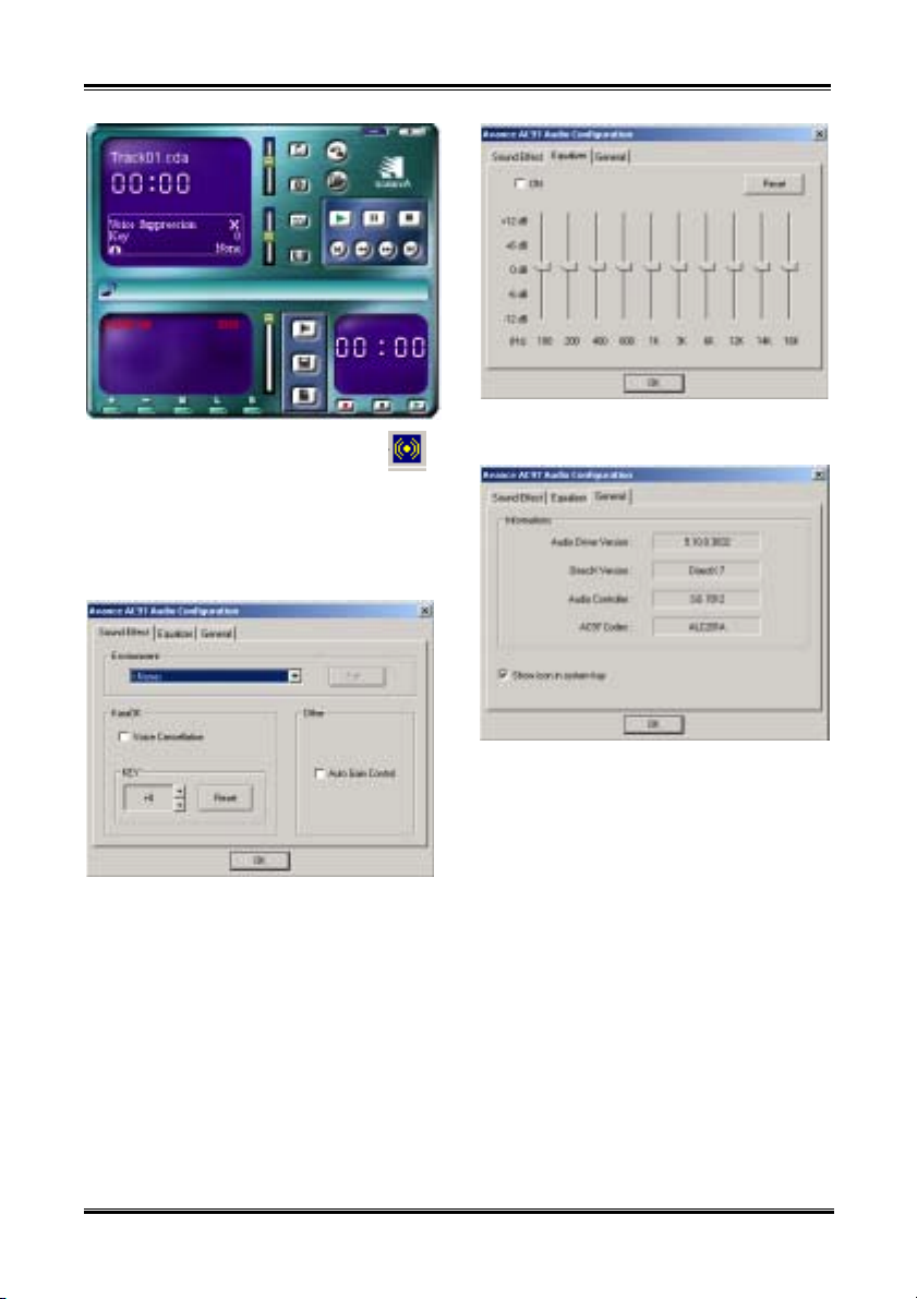
Audio Drivers Installation for Windows® 2000
C-3
You can click on the audio configure icon
on the task bar, and you can see the AvRack
panel as above.
The following diagrams will show you the
“Avance AC97 Audio Configuration”
application software each menu item.
This menu item can let you set environmental
and KaraOK key factor.
This menu item can let you set specific frequency
dB value.
Thi smenu item can give you the information
such as: audio driver version, DirectX version,
audio controller name, AC97 Codec name.
User’s Manual
Page 92

C-4
Appendix C
SR7-8X
Page 93
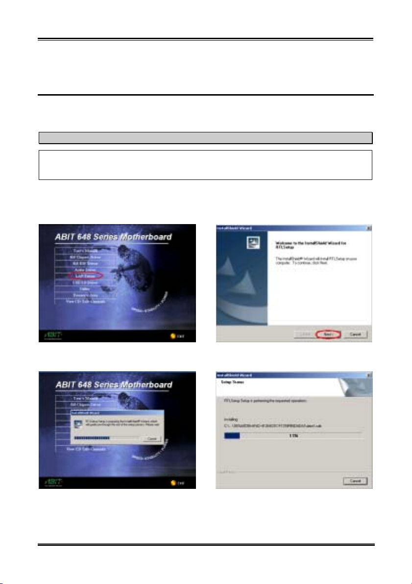
LAN Drivers Installation for Windows® 2000
D-1
Appendix D. LAN Drivers Installation for Windows®
2000
After you’ve installed SiS chipset drivers, you will need to install the LAN drivers. Step by step
instructions on how to do this are found in the following section.
Note
Details of the Windows® 2000 operating system will not be mentioned in this manual. If you have any
problems with Windows® 2000 installation, operations, or settings, please refer to your Windows®
2000 user's manual or other databases provided by Microsoft® Corporation.
Insert the 648 series CD into your CD-ROM drive, and it should execute the program automatically. If
not, you can go to the CD location and execute the execution file at the main directory of the CD. After it
has been executed you will see the screen below.
Step 1: Move the cursor to “LAN Driver” and
click on it. You will go to the next screen.
Step 2: The “InstallShield Wizard” shows up,
and it will go to the next screen for a while.
User’s Manual
Step 3: You will now see the welcome screen
and its dialogue box. Click “Next>” to go on.
Step 4: The installer will show the install
progress percentage.
Page 94
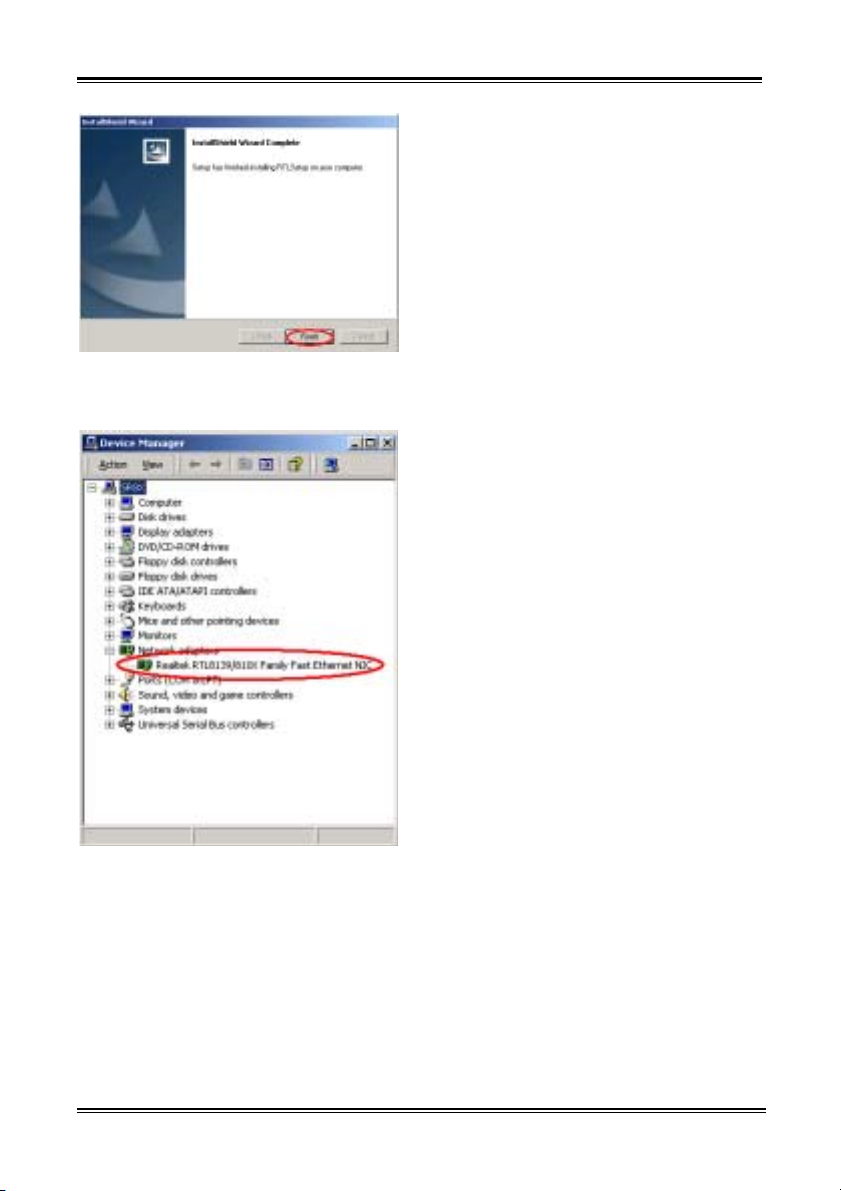
D-2
Appendix D
Step 5: Windows has completed installing the
driver. Click “Finish” to end the driver
installation.
Step 8: When system restarts and enters the
operating system, you can then check the
“Device Manager” see that the devices are
properly installed.
SR7-8X
Page 95
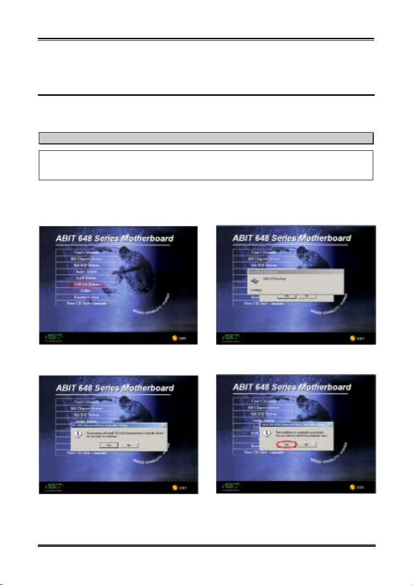
USB 2.0 Drivers Installation for Windows® 2000
E-1
Appendix E. USB 2.0 Drivers Installation for
Windows
After you’ve installed SiS chipset drivers, you will need to install the USB 2.0 drivers. Step by step
instructions on how to do this are found in the following section.
Details of the Windows® 2000 operating system will not be mentioned in this manual. If you have any
problems with Windows® 2000 installation, operations, or settings, please refer to your Windows®
2000 user's manual or other databases provided by Microsoft® Corporation.
Insert the 648 series CD into your CD-ROM drive, and it should execute the program automatically. If
not, you can go to the CD location and execute the execution file at the main directory of the CD. After it
has been executed you will see the screen below.
Step 1: Move the cursor to “USB 2.0 Driver”
and click on it. You will go to the next screen.
®
2000
Note
Step 3: The installer will found new hardware.
Step 2: The “InstallShield Wizard” shows up,
and it will go to the next screen for a while.
User’s Manual
Step 4: Windows has completed installing the
driver. Click “Yes” button to restart your
computer and finish the driver update.
Page 96
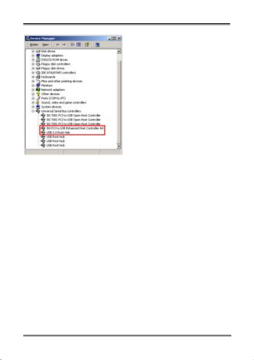
E-2
Appendix E
Step 5: When system restarts and enters the
operating system, you can then check the
“Device Manager” see that the devices are
properly installed.
SR7-8X
Page 97
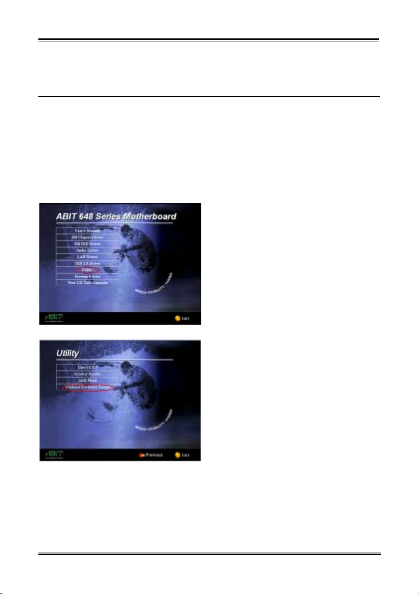
Installing The Winbond Hardware Monitor Software
F-1
Appendix F. Installing The Winbond Hardware
Monitor Software
The Winbond hardware monitor software is a self-diagnostic system for PCs. It will protect PC hardware
by monitoring several critical items including power supply voltage, CPU and system fan speeds, and
CPU and system temperatures. These items are important for the operation of the system; errors may
result in permanent damage to the PC. Once any item is out of its normal range, a warning message will
pop up and remind the user to take proper measures.
The following description will tell you how to install the Winbond hardware monitor software and use it.
Insert the 648 series CD into your CD-ROM drive. It should execute the program automatically. If not,
you can go to the CD location and execute the execution file from the main directory of this CD. After it
is executed, you will see the screen below.
Click “Utility” button.
Click “Winbond Hardware Doctor” button to start
install the hardware monitor system utility.
User’s Manual
Page 98
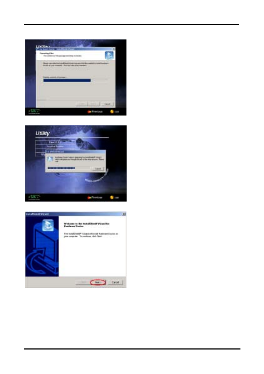
Appendix F
F-2
You will see the program extracting files.
You will see the install shell wizard active.
The welcome screen and its dialogue box will
appear. Click the “Next>” button to go on.
SR7-8X
Page 99
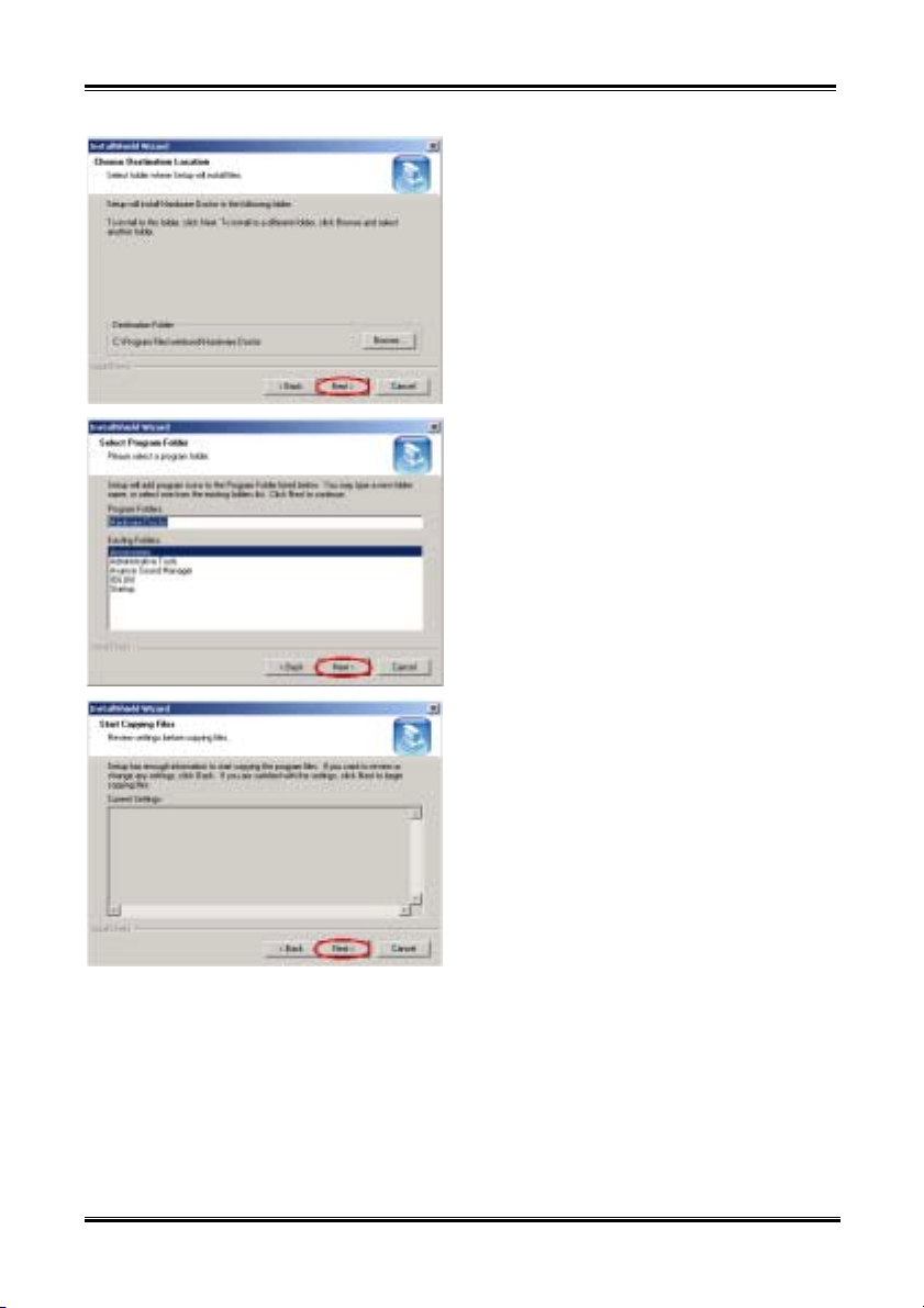
Installing The Winbond Hardware Monitor Software
Now you can choose the destination location where
you want to install the drivers. We suggest that you
use the default folder as the destination location.
After checking the folder click “Next>” button.
You can choose the name of the program folder. We
suggest you use the default program folder name.
After checking the program folder name then click
“Next>” button.
Program will start to install drivers the system
needs.
The installer is ready to start coping files, click
“Next>” button to go on.
F-3
User’s Manual
Page 100
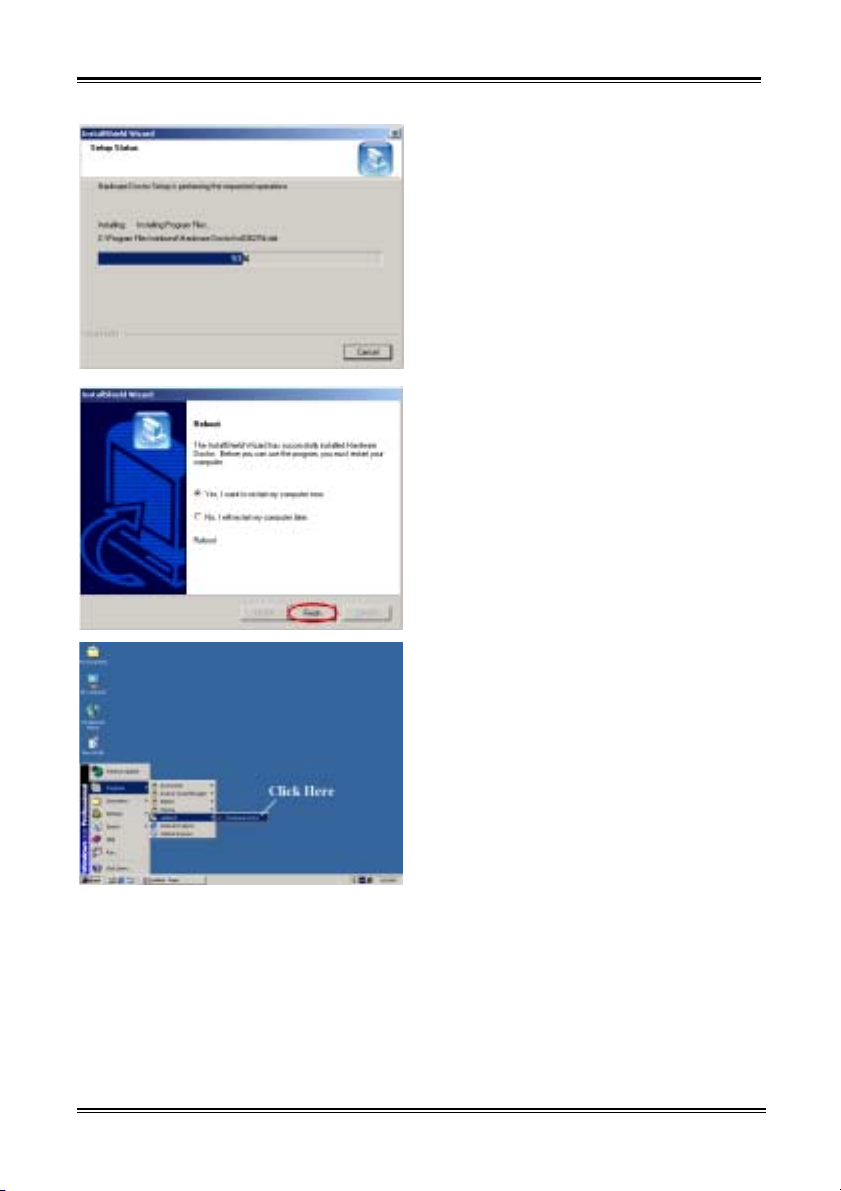
Appendix F
F-4
The wizard will start installing the program file. The
installer will show the install progress percentage.
When the installation is complete, the installer will
ask you to restart your computer. We suggest that
you choose “Yes, I want to restart my computer
now.” then click the “Finish” button to restart your
computer to finish the driver update.
You can select the program from Start toolbar, and
then choose Programs. You will see the item called
“winbond” ( “Hardware Doctor”. Click it, and
you will be able to see the screen below.
SR7-8X
 Loading...