


Copyright and Warranty Notice
The information in this document is subject to change without notice and does not represent a commitment on part of the vendor, who assumes no liability or responsibility for any errors that may appear in this manual.
No warranty or representation, either expressed or implied, is made with respect to the quality, accuracy or fitness for any particular part of this document. In no event shall the manufacturer be liable for direct, indirect, special, incidental or consequential damages arising from any defect or error in this manual or product.
Product names appearing in this manual are for identification purpose only and trademarks and product names or brand names appearing in this document are property of their respective owners.
This document contains materials protected under International Copyright Laws. All rights reserved. No part of this manual may be reproduced, transmitted or transcribed without the expressed written permission of the manufacturer and authors of this manual.
If you do not properly set the motherboard settings causing the motherboard to malfunction or fail, we cannot guarantee any responsibility.
BH6 Motherboard
USER’S MANUAL
|
|
|
Table of Contents |
|
|
|
|
|
|
|
|
Chapter |
1 |
Introduction of BH6 Features |
|
(1) |
|
Specifications |
1-1 |
|
|
Layout diagram |
1-3 |
|
|
The system block diagram |
1-4 |
|
|
|
|
Chapter |
2 |
Installing the Motherboard |
|
|
|
Installing the Motherboard to the Casing |
2-2 |
|
|
Standard External Connectors |
2-4 |
|
|
Jumper and Switches |
2-9 |
(4) |
|
Installation of the Pentium II/III, Celeron™ CPU |
2-10 |
(5) |
|
Installing System Memory |
2-11 |
|
|
|
|
Chapter |
3 |
Introduction of BIOS |
|
(1) |
|
CPU Setup |
3-3 |
(2) |
|
Standard CMOS Setup Menu |
3-8 |
(3) |
|
BIOS Features Setup Menu |
3-11 |
(4) |
|
Chipset Features Setup Menu |
3-17 |
(5) |
|
Power Management Setup Menu |
3-21 |
(6) |
|
PNP/PCI Configuration |
3-28 |
(7) |
|
Load Setup Defaults |
3-30 |
(8) |
|
Integrated Peripherals |
3-31 |
(9) |
|
Password Setting |
3-35 |
(10) |
IDE Hard Disk Detection |
3-35 |
|
(11) |
Save & Exit Setup |
3-36 |
|
(12) |
Exit Without Saving |
3-36 |
|
Part No: MN-130-2A5-51 |
Rev:1.05 |
Appendix A Quick Installation
Appendix B General Discussion About HDD Installation
Appendix C Flash BIOS User Instructions
Appendix D How to install the IDE Bus Master driver
Appendix E How to install the PCI bridge driver for 440BX chipset
Appendix F Install HighPoint XStore Pro Utility
Appendix G Technical Support

Introduction Of BH6 Features |
1-1 |
Chapter 1 Introduction Of BH6 Features
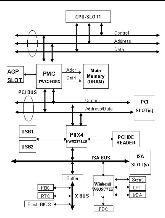
The motherboard is designed for a new generation CPUs. It supports the Intel SLOT1 structure (Pentium II/III and Celeron™ processors), up to 768MB of memory, super I/O, and Green PC functions. The motherboard provides high performance for server systems and meets the requirements for desktop system for multimedia in the future.
(1)Specifications
1.CPU
z CPU SOFT MENU™ II eliminates the need for jumpers or DIP switches
needed to set CPU parameters
z Employs switching type regulators to stabilize CPU operation z Supports 66 and 100MHz MHz CPU external clock speeds
z Supports Intel® Pentium® III 450 ~ 500MHz processor cartridge (Based on
100MHz)
z Supports Intel® Pentium® II 350 ~ 450MHz processor cartridge (Based on 100MHz) and Pentium® II 233 ~ 333MHz processor cartridge (Based on
66MHz)
z Supports Intel® Celeron™ 266MHz~433MHz processor (Based on 66MHz)
2. Chipset
zIntel® 440BX chipset (82443BX and 82371EB)
zSupports Ultra DMA/33 IDE protocol
zSupports Advanced Configuration and Power Management Interface(ACPI)
zAccelerated Graphics Port connector supports AGP 1x and 2x mode (Sideband) 3.3V device
3.Cache Memory
zLevel 1 and Level 2 cache built into Intel® Pentium® II/III processor cartridge
z Level 1 cache (without L2 cache) built into Intel® Celeron™ processorn
4. Memory (DRAM)
zThree 168-pin DIMM sockets support SDRAM modules
zSupports up to 768MB
zECC support
5.System BIOS
zAWARD BIOS
zSupports Plug-and-Play (PnP)
zSupports Advanced Configuration Power Interface (ACPI)
zSupports Desktop Management Interface (DMI)
zYear 2000 compliant
1-2 |
Chapter 1 |
Multi I/O Functions
zýFloppy port supports up to 2.88MB, and 3 mode floppies zýUltra DMA/33 bus master IDE supports up to 4 IDE devices
( Including LS-120 MB floppy drive )
zýBuilt-in Standard/EPP/ECP parallel port connector
zýTwo built-in 16550 fast UART compatible serial port connectors zýBuilt-in PS/2 keyboard and PS/2 mouse port connectors
z Built-in standard IrDA TX/RX header zýTwo built-in USB connectors
Miscellaneous
zýATX form factor
zýOne AGP slot, Five PCI slots and Two ISA slots zýWake Up On LAN header
zýSB-LINK header
z Hardware monitoring Included fan speed, voltages, and system environment temperature
zýBoard size: 305 * 190mm
Note: All brand names and trademarks are the property of their respective owners. n Only Celeron™ 300A and 333 processors have built in Level 2 cache.
” Above 66MHz/100MHz bus speed supported but not guaranteed due to the PCI and chipset specs.
” Sound Blaster™ is a registered trademark of Creative Technology Ltd in the United States and certain other countries. Sound Blaster-LINK™ and SB-LINK™ are trademarks of Creative Technology Ltd.
” Specifications and information contained in this manual are subject to change without notice.

Introduction Of BH6 Features |
1-3 |
(2) Layout Diagram
Figure 1-1 Motherboard Component Locations
1-4 |
Chapter 1 |
(3) The System Block Diagram

Installing the Motherboar |
2-1 |
Chapter 2 Installing the Motherboard
This BH6 motherboard not only provides all standard equipment for classic personal computers, but also provides great flexibility for meeting future upgrade demands. This chapter will introduce step by step all the standard equipment and will also present, as completely as possible, future upgrade capabilities. This motherboard is able to support all Intel Pentium II/III processors and Intel Celeron™ processor now on the market. (For details, see specifications in Chapter 1.)
This chapter is organized according the following features:
Installing the Motherboard to the Casing
Standard external connectors
Jumpers and switches
(4) |
Installation of the Pentium II/III, Celeron™ CPU |
(5) |
Installing the system memory |
1111
Before proceeding with the installation
Before installing the motherboard please be sure to turn off or disconnect the power supply unit. Before making any modifications to the hardware configuration of the motherboard, the power supply to any areas of the motherboard you plan to modify should be turned off to avoid unnecessary damage to the hardware.
)
User friendly instructions
Our objective is to enable the novice computer user to perform the installation by themselves. We have attempted to write this document in a very clear, concise and descriptive manner to help overcome any obstacles you may face during installation. Please read our instructions carefully and follow them step-by-step.
2-2 |
Chapter 2 |
Installing the Motherboard to the Casing
Most computer chassis will have a base on which there will be many mounting holes that allows the motherboard to be securely attached and at the same time, prevents short circuits.
There are two ways to attach the motherboard to the base of chassis:
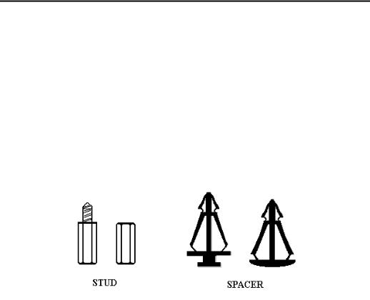
zwith stud zor with spacer
Please refer the figure below show the studs and spacers, they may have several types, but all look like the figure below:
In principle, the best way to attach the motherboard is with studs, and only if you are unable to do this should you attach the board with spacers. Take a careful look at the motherboard and you will see many mounting holes on it. Line these holes up with the mounting holes on the base. If the holes line up, and there are screw holes this means you can attach the motherboard with studs. If the holes line up and there are only slots, this means you can only attach the motherboard with spacers. Take the tip of the spacers and insert it into the slots. After doing this to all the slots, you can slide the motherboard into position aligned with the slots. After the motherboard has been positioned, check to make sure everything is OK before putting the casing back on.
The figure below will show you the way to fix the motherboard using with the stub and spacer:
Installing the Motherboar |
2-3 |
Note: If the motherboard has mounting holes, but don’t line up with the holes on the base and their are no slots to attach the spacers, don’t worry, you can still attach the spacers to the mounting holes. Just cut the button portion of spacers (the spacer may be a little and hard to cut off, so be careful of your hands). In this way you can still attach the motherboard to the base without worrying about short circuits.
Sometimes you may need to use the plastics spring for isolate the screw from motherboard PCB surface, because the circuit wire may be near by the hole. Be careful don’t let the screw to contact any printed circuit wire and parts on PCB that near by the fixing hole, otherwise it may damage the board or cause the board malfunction.
2-4 |
Chapter 2 |
Standard External Connectors
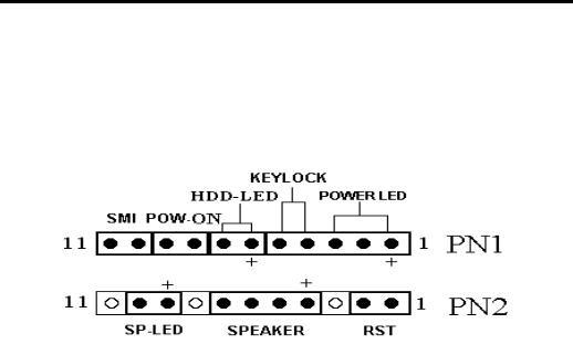
Inside the case of any computer several cables and plugs have to be connected. These cables and plugs are usually connected one-by-one to connectors located on the motherboard. You need to carefully pay attention to any connection orientation the cables may have and, if any, notice the position of the first pin of the connector. In the explanations that follow, we will describe the significance of the first pin.
PN1(Pin 1-2-3-4-5): Keylock and Power LED Header
There is a specific orientation for pin 1 through pin 5. Insert the two-threaded keylock cable into pin 4 and pin 5, and three-threaded power LED cable to Pin 1~pin 3. Check to make sure the correct pins of connector on the motherboard.
Pin number |
Name or significance of signal |
Connector Name |
1 |
+5VDC |
Power LED |
2 |
No connection |
Power LED |
3 |
Ground |
Power LED |
4 |
Keyboard inhibit Signal |
Keylock |
5 |
Ground |
Keylock |
PN1(Pin 6-7): HDD LED Header
Attach the cable from the case’s HDD LED to this connector.
Pin number |
Name or significance of signal |
6 |
LED power |
7 |
HDD active |
Installing the Motherboar |
2-5 |
PN1 (Pin 8-9): Power Switch Header
Pin number |
Name or significance of signal |
8 |
Ground |
9 |
Power On/Off switch |
PN1 (Pin 10-11): Hardware Suspend Switch (SMI Switch)
Header
Attach the cable from the case’s suspend switch (if there is one) to this switch. Use this switch to enable/disable the power management function by hardware.
Pin number |
Name or significance of signal |
10 |
+3V Standby |
11 |
Suspend signal |
Note: If you enable the ACPI function in the BIOS setup, this function will not
work.
PN2(Pin 1-2): Hardware Reset Header
Attach the cable from the case’s Reset switch to this connector. Press and hold the reset button for at least one second to reset the system.
Pin number |
Name or significance of signal |
1 |
Ground |
2 |
Reset input |
PN2(Pin 4-5-6-7): Speaker Header
Attach the system speaker to connector PN2.
Pin number |
Name or significance of signal |
4 |
+ 5VDC |
5 |
Ground |
6 |
Ground |
7 |
Speaker data |
2-6 |
Chapter 2 |
PN2(Pin 9-10): Suspend LED Header
Pin number |
Name or significance of signal |
9 |
LED power |
10 |
Suspend LED active |
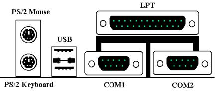
KM1 MOUSE: PS/2 Mouse Connector
Attach a PS/2 mouse to this 6-pin Din-connector.
Pin number |
Name or significance of signal |
1 |
Mouse data |
2 |
No connection |
3 |
Ground |
4 |
+5VDC |
5 |
Mouse clock |
6 |
No connection |
KM1 KB: PS/2 Keyboard Connector
Attach a keyboard to this 6-pin Din-connector.
Pin number |
Name or significance of signal |
1 |
Keyboard data |
2 |
No connection |
3 |
Ground |
4 |
+5VDC |
5 |
Keyboard clock |
6 |
No connection |

Installing the Motherboar |
2-7 |
CONT1: ATX Power Input Connector
Caution: If power supply connectors are not properly attached to ATX
PWR, the power supply or add-on cards may be damaged.
Attach the connectors from the power supply to CONT1.
Pin number |
Name or significance of signal |
1 |
+3.3VDC |
2 |
+3.3VDC |
3 |
Ground |
4 |
+5VDC |
5 |
Ground |
6 |
+5VDC |
7 |
Ground |
8 |
Power Good |
9 |
+5VSB |
10 |
+12VDC |
11 |
+3.3VDC |
12 |
-12VDC |
13 |
Ground |
14 |
On/Off control signal |
15 |
Ground |
16 |
Ground |
17 |
Ground |
18 |
-5VDC |
19 |
+5VDC |
20 |
+5VDC |
FAN1(CPU FAN), FAN2: DC Fan Power Header
Pin number |
Name of the signal or signification |
1 |
Ground |
2 |
+12V |
3 |
Sense signal |
2-8 Chapter 2
IR1: IR Header (Infrared)
Pin number |
Name or significance of signal |
1 |
+5V |
2 |
No connection |
3 |
IR_RX |
4 |
Ground |
5 |
IR_TX |
I/O Port Connectors
Name |
Pin number |
Description |
IDE1 |
40 |
IDE channel 1 connector |
IDE2 |
40 |
IDE channel 2 connector |
FDC |
34 |
Floppy disk connector |
LPT |
25 |
Parallel port |
COM1 |
9 |
Serial port COM1 connector |
COM2 |
9 |
Serial port COM2 connector |
USB |
8 |
Universal serial Bus |
Notes: *IDE1, IDE2 are high performance PCI IDE connectors. Up to four IDE interface devices are supported.
WOL1: Wake On LAN Header
Pin number |
Name or significance of signal |
1 |
+5VSB |
2 |
GND |
3 |
Sense input |
SB1: SB-Link™ |
Header |
|
|
Pin number |
Name or significance of signal |
1 |
GNTA |
2 |
Ground |
3 |
KEY |
4 |
REQA |
5 |
Ground |
6 |
SERIRQ |

Installing the Motherboar |
2-9 |
(3) Jumper and Switches
You can set jumper switches on the motherboard to configure various hardware options. See Figure 1-1 for jumper locations.
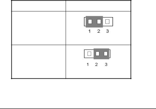
Throughout this section, the following symbols are used to indicate jumper settings.
For 3-pin jumpers, the symbols below are used:
Short Pins 1 and 2 with a jumper cap.
Short Pins 2 and 3 with a jumper cap.
For 2-pins jumpers, the following symbols are used:
Place the jumper cap over the two pins of the jumper to Short the jumper.
Remove the jumper cap to Open the jumper cap.
Note: To avoid losing jumper caps, attach the removed jumper cap to one of the jumper pins.
2-10 |
Chapter 2 |
CCMOS 1: CMOS Discharge Jumper
Jumper CCMOS discharge CMOS memory. When you install the motherboard, make sure this jumper is set for Normal Operation(1-2). See the jumper below.
Setting |
CCMOS |
Normal Operation
(Default)
Discharge CMOS
(4) Installation of the Pentium II/III, Celeron™ CPU
The installation method for the CPU is printed on the package of the retention mechanism that comes with the motherboard. You can refer to it while you install the CPU. This motherboard also supports the Celeron™ PPGA processor. If you want to install the Celeron™ PPGA processor, you have to use an additional adapter that allows you to use a Celeron™ PPGA processor in a slot 1 board. For this ABIT makes the SlotKET adapter.
Note:
zInstalling a heat sink and cooling fan is necessary for proper heat dissipation from your CPU. Failing to install these items may result in overheating and damage of your CPU.
zPlease refer to your boxed processor installation or other documentation attached with your CPU for detailed installing instructions.

Installing the Motherboar |
2-11 |
(5) Installing System Memory
The motherboard provides three 168-pin DIMM sites for memory expansion.. The DIMM socket supports 1Mx64(8MB), 2Mx64(16MB), 4Mx64(32MB), 8Mx64(64MB), 16Mx64(128MB), and 32Mx64(256MB) or double sided DIMM modules. Minimum memory size is 8MB and maximum memory size is 768MB SDRAM.
There are three Memory module sockets on the system board.(Total six banks)
In order to create a memory array, certain rules must be followed. The following set of rules allows for optimum configurations.
zThe memory array is 64 or 72 bits wide. (Without parity or with parity)
zThose modules can be populated in any order.
zSupport single and double density DIMMS.
The following is the valid memory configuration:
Bank |
Memory Module |
Total Memory |
|
|
|
Bank 0, 1 |
8MB, 16MB, 32MB, |
8MB ~ 256MB |
(DIMM1) |
64MB, 128MB, 256MB |
|
Bank 2, 3 |
8MB, 16MB, 32MB, |
8MB ~ 256MB |
(DIMM2) |
64MB, 128MB, 256MB |
|
Bank 4, 5 |
8MB, 16MB, 32MB, |
8MB ~ 256MB |
(DIMM3) |
64MB, 128MB, 256MB |
|
Total System Memory |
8MB ~ 768MB |
|
|
|
|
2-12 Chapter 2
Supported SDRAM Memory Configurations
DRAM |
DRAM |
DRAM |
DRAM |
DRAM DIMM |
DRAM |
|
MA |
|
DARM |
||
|
|
|
|
||||||||
|
|
|
|
|
|
|
|
|
|
Size |
|
Type |
Tech |
Depth |
Width |
SS |
DS |
Addressing |
Row |
Col |
Banks |
Min |
Max |
|
|
|
|
||||||||
|
|
|
|
x64 |
x64 |
|
|
|
|
(1 row) |
(2 row) |
SDRAM |
16M |
1M |
16 |
1M |
2M |
Asymmetric |
12 |
8 |
2 |
8MB |
16MB |
|
|
|
|
|
|
|
|
|
|
|
|
|
|
2M |
8 |
2M |
4M |
Asymmetric |
12 |
9 |
2 |
16MB |
32MB |
|
|
|
|
|
|
|
|
|
|
|
|
|
|
2M |
8 |
2M |
4M |
Asymmetric |
13 |
8 |
2 |
16MB |
32MB |
|
|
|
|
|
|
|
|
|
|
|
|
|
|
4M |
4 |
4M |
8M |
Asymmetric |
12 |
10 |
2 |
32MB |
64MB |
|
|
|
|
|
|
|
|
|
|
|
|
|
|
4M |
4 |
4M |
8M |
Asymmetric |
14 |
8 |
2 |
32MB |
64MB |
|
|
|
|
|
|
|
|
|
|
|
|
SDRAM |
64M |
2M |
32 |
2M |
4M |
Asymmetric |
12 |
9 |
2 |
16MB |
32MB |
|
2 Bank |
|
|
|
|
|
|
|
|
|
|
|
2M |
32 |
2M |
4M |
Asymmetric |
13 |
8 |
2 |
16MB |
32MB |
|
|
|
|
|
|
|
|
|
|
|
|
|
|
|
4M |
16 |
4M |
8M |
Asymmetric |
12 |
10 |
2 |
32MB |
64MB |
|
|
|
|
|
|
|
|
|
|
|
|
|
|
4M |
16 |
4M |
8M |
Asymmetric |
14 |
8 |
2 |
32MB |
64MB |
|
|
|
|
|
|
|
|
|
|
|
|
|
|
8M |
8 |
8M |
16M |
Asymmetric |
14 |
9 |
2 |
64MB |
128MB |
|
|
|
|
|
|
|
|
|
|
|
|
|
|
16M |
4 |
16M |
32M |
Asymmetric |
14 |
10 |
2 |
128MB |
256MB |
|
|
|
|
|
|
|
|
|
|
|
|
SDRAM |
64M |
2M |
32 |
2M |
4M |
Asymmetric |
13 |
8 |
4 |
16MB |
32MB |
|
4 Bank |
|
|
|
|
|
|
|
|
|
|
|
4M |
16 |
4M |
8M |
Asymmetric |
14 |
8 |
4 |
32MB |
64MB |
|
|
|
|
|
|
|
|
|
|
|
|
|
|
|
8M |
8 |
8M |
16M |
Asymmetric |
14 |
9 |
4 |
64MB |
128MB |
|
|
|
|
|
|
|
|
|
|
|
|
|
|
16M |
4 |
16M |
32M |
Asymmetric |
14 |
10 |
4 |
128MB |
256MB |
|
|
|
|
|
|
|
|
|
|
|
|
Introduction of BIOS |
3-1 |
Chapter 3 Introduction of BIOS
The BIOS is a program located on a Flash Memory chip on the motherboard. This program will not be lost when you turn the computer off. This program is also referred to as the boot program. It is the only channel for the hardware circuit to communicate with the operating system. Its main function is to manage the setup of the motherboard and interface cards parameters, including simple parameters such as time, date, hard disk drive, as well as more complex parameters such as hardware synchronization, device operating mode, CPU SOFT MENU™ II techniques, setup of CPU speed. The computer will operate normally, or will operate at its best, only if all these parameters are correctly configured through the BIOS.
0Don’t change the parameters inside the BIOS unless you know what you are doing
The parameters inside the BIOS are used to setup the hardware synchronization or the device operating mode. If the parameters are not correct, they will produce errors, the computer will crash, and sometimes you will even not be able to boot the computer after it has crashed. We recommend that you do not change the parameters inside the BIOS unless you are familiar with them. If you are not able to boot your computer anymore, please refer to the section “Erase CMOS data” in Chapter 2.
When you start the computer, it is controlled by the BIOS program. The BIOS first operates an auto-diagnostic for all the necessary hardware, configures the parameters of the hardware synchronization, and detects all the hardware. Only when these tasks are completed does it give up control of the computer to the program of the next level, which is the operating system. Since the BIOS is the only channel for hardware and software to communicate, it will be the key factor for system stability, and to ensure that your system performs at its best. After the BIOS has achieved the auto-diagnostic and auto-detection operations, it will display the following message:
PRESS DEL TO ENTER SETUP
Three to five seconds after the message is displayed, if you press the Del key, you will access the BIOS Setup menu. At that moment, the BIOS will display the following message:
3-2 |
Chapter 3 |
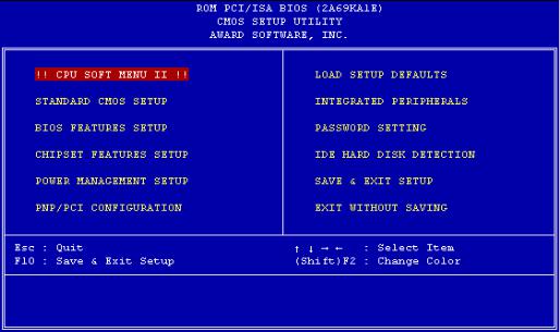
Fig 3-1 CMOS Setup Utility
In the BIOS Setup main menu of Figure 3-1, you can see several options. We will explain these options step by step in the following pages of this chapter, but let us first see a short description of the function keys you may use here:
zPress Esc to quit the BIOS Setup.
zPress (up, down, left, right) to choose, in the main menu, the option you want to confirm or to modify.
zPress F10 when you have completed the setup of BIOS parameters to save these parameters and to exit the BIOS Setup menu.
zPress Page Up/Page Down or +/- keys when you want to modify the BIOS parameters for the active option.
CMOS DATA
Computer Maybe you have heard somebody saying that their CMOS knowledge DATA was lost. What is the CMOS? Is it important? The CMOS is the memory used to store the BIOS parameters that you have configured. This memory is passive. You can read its data, and you can also store data in it. But this memory has to be powered by a battery, in order to avoid any loss of its data when the computer is turned off. Since you may have to change the CMOS battery when it is out of power and if doing so, you will loose all CMOS data, therefore, we recommend that you write down all the parameters of your hardware, or to
put a label with these parameters on your hard disk.
Introduction of BIOS |
3-3 |
(1) CPU Setup <CPU SOFT MENU™ |
II> |
The CPU can be setup through a programmable switch (CPU SOFT MENU™
II), that replaces traditional manual hardware configuration. This feature allows the user to complete more easily the installation procedures. You can install the CPU without configuring any jumpers or switches. The CPU must be setup according its specifications.
In the first option, you can press <F1> at any time to display all the items that can be chosen for that option.
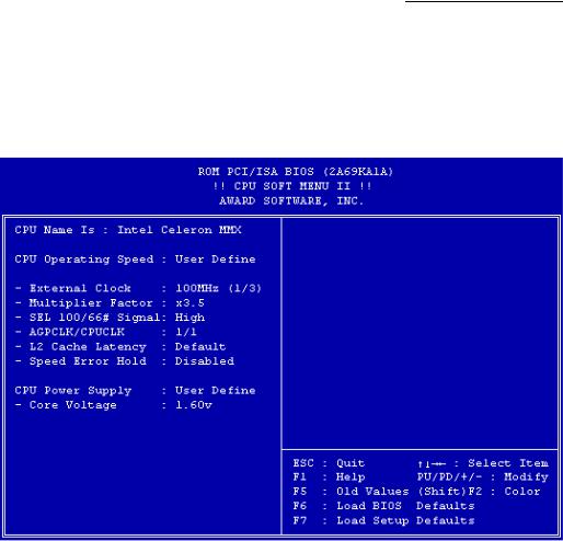
Fig 3-2 CPU SOFT MENU™ II
CPU Name Is:
³Intel Pentium III MMX
³Intel Pentium II MMX
³Intel Celeron MMX

3-4 |
Chapter 3 |
CPU Operating Speed:
This option sets the CPU speed.
In this field, the CPU speed is indicated like this:
CPU speed = External clock * Multiplier factor, select the CPU speed according the type and the speed of your CPU.
<Note 1> For Intel Pentium® |
II and Pentium® III MMX processors, you can |
|||
choose the following settings: |
|
|
||
³ 233 (66*3.5) |
|
³ 266 (66*4) |
³300 (66*4.5) |
|
³ 333 (66*5) |
|
³ 350 (100*3.5) |
³400 (100*4) |
|
³ 450 (100*4.5) |
³ 500 (100*5.0) |
………… |
||
For Intel Celeron™ |
MMX processors, you can choose the following |
|||
settings: |
|
|
|
|
³266(66*4) |
|
³300(66*4.5) |
³300A(66*4.5) |
|
³333(66*5.0) |
|
³366(66*5.5) |
³400(66*6) |
|
³433(66*6.5) |
|
…… |
|
|
<Note 2> User define external clock and multiplier factor: |
||||
³ User Define |
|
|
|
|
î External Clock: |
|
|
||
³ 66MHz |
³ 75MHz* |
³ 83MHz* |
³ 100MHz |
|
³ 112MHz* |
³ 124MHz* |
³ 133MHz* |
………… |
|
Note: *Above 66MHz/100MHz bus speed supported but not guaranteed due to the PCI and chipset specs.
î Multiplier Factor:
You can choose the following multiplier factors:
³ 2.0 |
³ 2.5 |
³ 3.0 |
³ 3.5 |
³ 4.0 |
³ 4.5 |
³ 5.0 |
³ 5.5 |
³ 6.0 |
³6.5 |
³ 7.0 |
³ 7.5 |
³ 8.0 |
………… |
|
However, differences will exist because of the various brands and types available.
<Note 3> SEL100/66# Signal:
This default setting is “High” at 100MHz, and “Low” at 66MHz. When you want to try a higher multiplier factor at 100MHz and cannot chose it in “High” state, then you can set it to “Low” state.
Note: According to Pentium® II/III processor types, some Pentium® II/III processors will have locked up the multiplier factor and disable this signal. In this situation, there is no way to choose the higher multiplier factor.
<Note 4> AGPCLK/CPUCLK:

Introduction of BIOS |
3-5 |
Default setting is “ 2/3”. In this state, AGP bus speed will be CPU bus speed divided by 3 and times 2. If you choose the setting to “ 1/1 ”, AGP bus speed will equal to CPU bus speed.
<Note 5> L2 Cache Latency:
Sixteen setting are available, Default, and 1 to 15. This item can let you adjust the processor L2 cache speed, the larger the value, the faster the L2 cache will run. You have to be aware that if you set the L2 cache speed too fast, it will cause the L2 cache to fail. If the L2 cache fails it will cease to run until you reset the value, but the processor and L1 cache will still function, just not as well. To make sure your L2 cache functions properly please choose an appropriate setting. The default setting is Default.
<Note 6> Speed Error Hold:
Default setting is “Disable”. If you choose the setting to “Enable”, when CPU speed setting is wrong, then system will hold.
Normally, we do not recommend that you use the “User Define” option to setup CPU speed and multiplier factor. This option is for setup of future CPUs whose specifications are still unknown. The specifications of all present CPUs are included in the default settings. Unless you are very familiar with all CPU parameters, it is very easy to make mistakes when you define by yourself the external clock and the multiplier factor.
Solution in case of booting problem due to invalid clock setup:
Normally, if the CPU clock setup is wrong, you will not be able to boot. In this case, turn the system off than on again. The CPU will automatically use its standard parameters to boot. You can then enter BIOS Setup again and set up the CPU clock.
If you can’t enter BIOS setup , you must try turning the system on a few times (3~4 times) or press “ INSERT “ key when turn on and the system will automatically use its standard parameters to boot. You can then enter BIOS SETUP again and set up the new parameters.
When you change your CPU:
The motherboard have been designed in such a way that you can turn the system on after having inserted the CPU in the socket without having to configure any jumpers or DIP switches. But if you change your CPU, normally, you just have to turn off the power supply, change the CPU and then, set up the CPU parameters through CPU SOFT MENU™ II. However, if the CPU brand and type is the same, and if the new CPU is slower than the old one, we offer you two methods to successfully complete the CPU change operation.
3-6 |
Chapter 3 |
Method 1: Setup up the CPU for the lowest speed for its brand. Turn the power supply off and change the CPU. Then turn the system on again, and set up the CPU parameters through CPU SOFT MENU™ II.
Method 2: Since you have to open the computer case when you change the CPU, it could be a good idea to use the CCMOS jumper to erase the parameters of the original CPU and to enter BIOS Setup to set up CPU parameters again.
Attention: After setting up the parameters and you leave the BIOS SETUP, and you have verified that the system can be booted, do not press the Reset button or turn off the power supply. Otherwise the BIOS will not read correctly, the parameters will fail and you must enter CPU SOFT MENU™ II again to set up the parameters all over again.
CPU Power Supply:
This option allows you to switch between CPU Default and user define voltage.
³CPU Default: System will detect CPU type and select proper voltage automatically. When it is enabled ,the option “ Core Voltage” will show the current voltage setting that is defined by the CPU and this will not be changeable. We recommend using this CPU default setting and not changing it unless current CPU type and voltage setting can not be detected or not correct.
³User define: This option lets the user select the voltage manually. You can change values of the “ Core Voltage” option lists by using the Page Up and Page Down keys.
Warning: The wrong settings of the multiplier and external clock in certain circumstances may cause CPU damage. Setting the working frequency higher than the PCI chipset or processor specs, may cause abnormal memory module functioning; system hangs; hard disk drive data lose; VGA card abnormal functioning, or abnormal functioning in other add-on cards. Using non-specification settings for your CPU is not the intention of this explanation. These should be used for engineering testing, not for normal applications.
Introduction of BIOS |
3-7 |
If you use non-specification settings for normal operation, your |
system may |
not be stable, and may effect system reliability. Also, we do not guarantee the stability and compatibility for settings that are not within specification, and any damage of any elements on the motherboard or peripherals, is not our responsibility.
3-8 |
Chapter 3 |
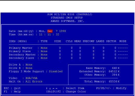
(2) Standard CMOS Setup Menu
This contains the basic configuration parameters of the BIOS. These parameters include the settings of date, hour, VGA card, FDD and HDD.
Fig 3-3 Standard CMOS Setup Menu
Date (mm:dd:yy):
You can set the date information in this item, month (mm), date (dd) and year (yy).
Time (hh:mm:ss):
You can set time information in this item, hour (hh), minute (mm) and second (ss).
Setup of HDD operating mode NORMAL, LBA, LARGE
Since old operating systems were only able to support HDD whose capacity was not bigger than 528MB, any hard disk with more than 528MB was unusable. AWARD BIOS features a solution to this problem: you can, according to your operating system, choose three operating modes: NORMAL, LBA or LARGE.
Introduction of BIOS |
3-9 |
The HDD auto detection option in the Main Menu will automatically detect
the parameters of your hard disk and the mode supported.
³ Normal mode:
Standard normal mode supports hard disks of 528MB or less. This mode directly uses positions indicated by Cylinders (CYLS), Heads, and Sectors to access data.
³ LBA (Logical Block Addressing) mode:
The earlier LBA mode can support HDDs capacity of up to 8.4GB, and this mode uses a different method to calculate the position of disk data to be accessed. It translates Cylinders (CYLS), Heads and Sectors into a logical address where data are located. The Cylinders, Heads, and Sectors displayed in this menu do not reflect the actual structure of the hard disk, they are just reference values used to calculate actual positions. Currently, all high capacity hard disks support this mode, that’s why we recommend you use this mode. Currently, the BIOS can support INT 13h extension function, then the LBA mode supports hard disk drives capacity exceeding 8.4GB.
³ LARGE Mode:
When the number of cylinders (CYLs) of the hard disk exceeds 1024 and DOS is not able to support it, or if your operating system does not support LBA mode, you should select this mode.
Drive A:
If you have installed the floppy disk drive here, then you can select the type of floppy drive it can support. Six options are available: NoneÎ360K,
5.25 in. Î1.2M, 5.25in. Î720K, 3.5 in. Î1.44M, 3.5 in. Î2.88M, 3.5 in.
Î
Drive B:
If you have installed the floppy disk drive here, then you can select the type of floppy drive it can support. Six options are available: NoneÎ360K,
5.25 in. Î1.2M, 5.25in. Î720K, 3.5 in. Î1.44M, 3.5 in. Î2.88M, 3.5 in.
Î
3-10 |
Chapter 3 |
FDD supporting 3 Mode:
3 Mode floppy disk drives (FDD) are 3 1/2” drives used in Japanese computer systems. If you need to access data stored in this kind of floppy, you must select this mode, and of course you must have a 3 Mode floppy drive.
Video:
You can select the VGA modes for your video adapter, five options are available: MONOÎEGA/VGA ÎCGA 40ÎCGA 80 ÎBack to MONO. The default setting is EGA/VGA.
Halt On:
You can select which type of error will cause the system to halt. Five options are available: All ErrorsÎNo ErrorsÎAll, But KeyboardÎAll, But DisketteÎAll, But Disk/KeyÎBack to All Errors.
You can see your system memory list in the lower right box, it shows the Base Memory, Extended Memory and Other Memory size in your system.
5 For further information about HDD installation, refer to Appendix B.
 Loading...