


 Loading...
NF-M2P NF-M2S NF-M2SV
Motherboard
AMD Socket AM2
Installation Guide
Copyright and Warranty Notice
The information in this document is subject to change without notice and does not represent a commitment on part of the vendor, who assumes no liability or responsibility for any errors that may appear in this manual.
No warranty or representation, either expressed or implied, is made with respect to the quality, accuracy or fitness for any particular part of this document. In no event shall the manufacturer be liable for direct, indirect, special, incidental or consequential damages arising from any defect or error in this manual or product.
Product names appearing in this manual are for identification purpose only and trademarks and product names or brand names appearing in this document are the property of their respective owners.
This document contains materials protected under International Copyright Laws. All rights reserved. No part of this manual may be reproduced, transmitted or transcribed without the expressed written permission of the manufacturer and authors of this manual.
If you do not properly set the motherboard settings, causing the motherboard to malfunction or fail, we cannot guarantee any responsibility.
The Following Information is Only for EU-member States:
Directive 2002/96/EC on Waste Electrical and Electronic Equipment (WEEE): The use of the symbol indicates that this product may not be treated as household waste. By Ensuring this product is disposed of correctly, you will help prevent potential negative consequences for the environment and human health, which could otherwise be cause by inappropriate waste handling of this product. For more detailed information about recycling of this product, please contact your local city office, your household waste disposal service or the shop where you purchased the product.
ii |
NF-M2P/NF-M2S/NF-M2SV |

Contents
1. Hardware Setup ................................................ |
1 |
|
1.1 |
Specifications ............................................................. |
1 |
|
1.1.1 NF-M2P ............................................................. |
1 |
|
1.1.2 NF-M2S ............................................................. |
2 |
|
1.1.3 NF-M2SV ........................................................... |
3 |
1.2 |
Motherboard Layout ................................................... |
4 |
|
1.2.1 NF-M2P ............................................................. |
4 |
|
1.2.2 NF-M2S ............................................................. |
4 |
|
1.2.3 NF-M2SV ........................................................... |
5 |
1.3 |
Choosing a Computer Chassis...................................... |
5 |
1.4 |
Installing Motherboard................................................ |
5 |
1.5 |
Checking Jumper Settings ........................................... |
6 |
|
1.5.1 CMOS Memory Clearing Header and Backup |
|
|
Battery ...................................................................... |
6 |
1.6 |
Connecting Chassis Components ................................. |
8 |
|
1.6.1 ATX Power Connectors ....................................... |
8 |
|
1.6.2 Front Panel Switches and Indicators Headers....... |
8 |
|
1.6.3 FAN Power Connectors ....................................... |
9 |
|
1.6.4 Chassis Speaker Connector................................. |
9 |
1.7 |
Installing Hardware .................................................. |
10 |
|
1.7.1 CPU Socket AM2 .............................................. |
10 |
|
1.7.2 DDR2 Memory Slots ......................................... |
11 |
1.8 |
Connecting Peripheral Devices................................... |
12 |
|
1.8.1 Floppy and IDE Disk Drive Connectors............... |
12 |
|
1.8.2 Serial ATA Connectors ...................................... |
13 |
|
1.8.3 Additional USB 2.0 Port Headers ....................... |
13 |
|
1.8.4 Internal Audio Connectors ................................ |
14 |
|
1.8.5 Front Panel Audio Connection Header ............... |
15 |
|
1.8.6 PCI and PCI Express X16, X1 Slots .................... |
15 |
1.9 |
Connecting Rear Panel I/O Devices............................ |
16 |
2. BIOS Setup ...................................................... |
17 |
|
3. Driver & Utility ................................................ |
18 |
|
4. Appendix ......................................................... |
19 |
|
4.1 |
.................................................... |
19 |
|
4.1.1 NF-M2P ........................................................... |
19 |
|
4.1.2 NF-M2S ........................................................... |
20 |
|
4.1.3 NF-M2SV ......................................................... |
21 |
4.2 |
.................................................... |
22 |
|
4.2.1 NF-M2P ........................................................... |
22 |
|
4.2.2 NF-M2S ........................................................... |
23 |
|
4.2.3 NF-M2SV ......................................................... |
24 |
4.3 |
Troubleshooting (How to Get Technical Support?) ...... |
25 |
|
4.3.1 Q & A.............................................................. |
25 |
|
4.3.2 Technical Support Form.................................... |
26 |
4.4 |
Contact Information.................................................. |
27 |
NF-M2P/NF-M2S/NF-M2SV |
iii |

iv |
NF-M2P/NF-M2S/NF-M2SV |
1. Hardware Setup
1.1 Specifications
1.1.1 NF-M2P
CPU
•Socket AM2 processor with 2000MT/s system bus
•Supports AMD Cool ‘n’ Quiet Technology
Chipset
• NVIDIA GeForce6100 + 430
Memory
•2x 240-pin DIMM slots support up to 2GB
•Supports Dual Channel DDR2 800/667/533 Un-buffered ECC/Non-ECC memory
Graphics
• Integrated NVIDIA GeForce6100 Graphics
LAN
• Onboard Gigabit LAN
Audio
• Onboard 7.1-Channel HD Audio CODEC
Serial ATA
• 4x SATA 3Gb/s support SATA RAID 0, 1, 10, 5, JBOD
Expansion Slots
•1x PCI-E X16 slot
•1x PCI-E X1 slot
•2x PCI slots
Internal I/O Connectors
•1x Floppy port
•1x ATA 133 IDE connector
•3x USB 2.0 headers
•4x SATA 3Gb/s connectors
•1x FP-Audio header
•1x CD-In connector
Rear Panel I/O
•1x PS/2 Keyboard connector
•1x PS/2 Mouse connector
•1x COM port
•1x LPT port
•1x VGA connector
•4x USB 2.0 connectors
•1x RJ-45 LAN connector
•1x 7.1-Channel Audio Connector
RoHS
• 100% Lead-free process and RoHS compliant
Miscellaneous
•Micro ATX form factor (244mm x 220mm)
•Vista HW Ready
Specifications and information contained herein are subject to change without notice.
NF-M2P/NF-M2S/NF-M2SV |
1 |
1.1.2 NF-M2S
CPU
•Socket AM2 processor with 2000MT/s system bus
•Supports AMD Cool ‘n’ Quiet Technology
Chipset
• NVIDIA GeForce6100 + 405
Memory
•2x 240-pin DIMM slots support up to 2GB
•Supports Dual Channel DDR2 800/667/533 Un-buffered ECC/Non-ECC memory
Graphics
• Integrated NVIDIA GeForce6100 Graphics
LAN
• Onboard Gigabit LAN
Audio
• Onboard 7.1-Channel HD Audio CODEC
Serial ATA
• 2x SATA 3Gb/s support SATA RAID 0, 1
Expansion Slots
•1x PCI-E X16 slot
•1x PCI-E X1 slot
•2x PCI slots
Internal I/O Connectors
•1x Floppy port
•1x ATA 133 IDE connector
•2x USB 2.0 headers
•2x SATA 3Gb/s connectors
•1x FP-Audio header
•1x CD-In connector
Rear Panel I/O
•1x PS/2 Keyboard connector
•1x PS/2 Mouse connector
•1x COM port
•1x LPT port
•1x VGA connector
•4x USB 2.0 connectors
•1x RJ-45 LAN connector
•1x 7.1-Channel Audio Connector
RoHS
• 100% Lead-free process and RoHS compliant
Miscellaneous
•Micro ATX form factor (244mm x 220mm)
•Vista HW Ready
Specifications and information contained herein are subject to change without notice.
2 |
NF-M2P/NF-M2S/NF-M2SV |

1.1.3 NF-M2SV
CPU
•Socket AM2 processor with 2000MT/s system bus
•Supports AMD Cool ‘n’ Quiet Technology
Chipset
• NVIDIA GeForce6100 + 405
Memory
•2x 240-pin DIMM slots support up to 2GB
•Supports Dual Channel DDR2 800/667/533 Un-buffered ECC/Non-ECC memory
Graphics
• Integrated NVIDIA GeForce6100 Graphics
LAN
• Onboard 10/100 LAN
Audio
• Onboard 5.1-Channel HD Audio CODEC
Serial ATA
• 2x SATA 3Gb/s support SATA RAID 0, 1
Expansion Slots
•1x PCI-E X16 slot
•1x PCI-E X1 slot
•2x PCI slots
Internal I/O Connectors
•1x Floppy port
•1x ATA 133 IDE connector
•2x USB 2.0 headers
•2x SATA 3Gb/s connectors
•1x FP-Audio header
•1x CD-In connector
Rear Panel I/O
•1x PS/2 Keyboard connector
•1x PS/2 Mouse connector
•1x COM port
•1x LPT port
•1x VGA connector
•4x USB 2.0 connectors
•1x RJ-45 LAN connector
•1x 5.1-Channel Audio Connector
RoHS
• 100% Lead-free process and RoHS compliant
Miscellaneous
•Micro ATX form factor (244mm x 220mm)
•Vista HW Ready
Specifications and information contained herein are subject to change without notice.
NF-M2P/NF-M2S/NF-M2SV |
3 |

1.2 Motherboard Layout |
1.2.2 NF-M2S |
1.2.1 NF-M2P
4 |
NF-M2P/NF-M2S/NF-M2SV |
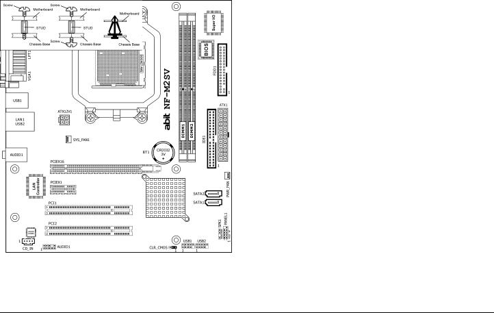
1.2.3 NF-M2SV
The motherboard and its component layouts illustrated in the following chapter of this manual were mainly based on model “NF-M2P”, unless specifically stated.
1.3 Choosing a Computer Chassis
•Choose a chassis big enough to install this motherboard.
•As some features for this motherboard are implemented by cabling connectors on the motherboard to indicators and switches or buttons on the chassis, make sure your chassis supports all the features required.
•If there is a possibility of adopting some more hard drives, make sure your chassis has sufficient power and space for them.
•Most chassis have alternatives for I/O shield located at the rear panel. Make sure the I/O shield of the chassis matches the I/O port configuration of this motherboard. You can find an I/O shield specifically designed for this motherboard in its package.
1.4 Installing Motherboard
Most computer chassis have a base with many mounting holes to allow the motherboard to be securely attached, and at the same time, prevent the system from short circuits. There are two ways to attach the motherboard to the chassis base: (1) with studs, or (2) with spacers.
Basically, the best way to attach the board is with studs. Only if you are unable to do this should you attach the board with spacers. Line up the holes on the board with the mounting holes on the chassis. If the holes line up and there are screw holes, you can attach the board with studs. If the holes line up and there are only slots, you can only attach with spacers. Take the tip of the spacers and insert them into the slots. After doing this to all the slots, you can slide the board into position aligned
NF-M2P/NF-M2S/NF-M2SV |
5 |
with slots. After the board has been positioned, check to make sure everything is OK before putting the chassis back on.
Always power off the computer and unplug the AC power cord before adding or removing any peripheral or component. Failing to so may cause severe damage to your motherboard and/or peripherals. Plug in the AC power cord only after you have carefully checked everything.
To install this motherboard:
1.Locate all the screw holes on the motherboard and the chassis base.
2.Place all the studs or spacers needed on the chassis base and have them tightened.
3.Face the motherboard’s I/O ports toward the chassis’s rear panel.
4.Line up all the motherboard’s screw holes with those studs or spacers on the chassis.
5.Install the motherboard with screws and have them tightened.
To prevent shorting the PCB circuit, please REMOVE the metal studs or spacers if they are already fastened on the chassis base and are without mounting-holes on the motherboard to align with.
This side faces the chassis’s rear panel.
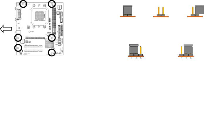
1.5 Checking Jumper Settings
For a 2-pin jumper, plug the jumper cap on both pins will make it CLOSE (SHORT). Remove the jumper cap, or plug it on either pin (reserved for future use) will leave it at OPEN position.
SHORT |
OPEN |
OPEN |
For a 3-pin jumper, pin 1~2 or pin 2~3 can be shorted by plugging the jumper cap in.
Pin 1~2 SHORT |
Pin 2~3 SHORT |
1.5.1CMOS Memory Clearing Header and Backup Battery
The time to clear the CMOS memory occurs when (a) the CMOS data becomes corrupted, (b) you forgot the supervisor or user password preset in the BIOS menu, (c) you are unable to boot-up the system because the CPU ratio/clock was incorrectly set in the BIOS menu, or (d) whenever there is modification on the CPU or memory modules.
This header uses a jumper cap to clear the CMOS memory and have it reconfigured to the default values stored in BIOS.
6 |
NF-M2P/NF-M2S/NF-M2SV |
Loading...