


AG8-V

AG8 Series
(AG8, AG8-V)
Intel Pentium 4 System Board
Socket 775
User’s Manual
4200-0399-05
Rev. 1.02

Copyright and Warranty Notice
The information in this document is subject to change without notice and does not
represent a commitment on part of the vendor, who assumes no liability or
responsibility for any errors that may appear in this manual.
No warranty or representation, either expressed or implied, is made with respect to the
quality, accuracy or fitness for any particular part of this document. In no event shall
the manufacturer be liable for direct, indirect, special, incidental or consequential
damages arising from any defect or error in this manual or product.
Product names appearing in this manual are for identification purpose only and
trademarks and product names or brand names appearing in this document are the
property of their respective owners.
This document contains materials protected under International Copyright Laws. All
rights reserved. No part of this manual may be reproduced, transmitted or transcribed
without the expressed written permission of the manufacturer and authors of this
manual.
If you do not properly set the motherboard settings, causing the motherboard to
malfunction or fail, we cannot guarantee any responsibility.
AG8 Series

Table Of Contents
Chapter 1. Introduction .......................................................................... 1-1
1-1. Features & Specifications ........................................................................1-1
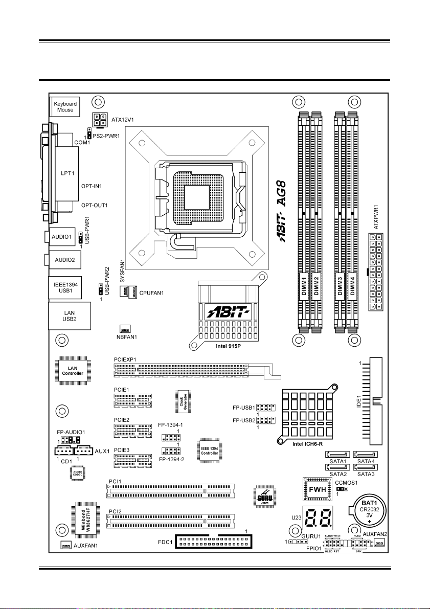
1-2. Layout Diagram (AG8)............................................................................1-3
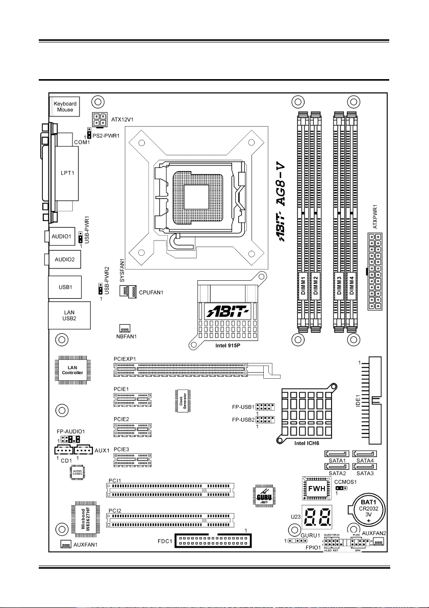
1-3. Layout Diagram (AG8-V)........................................................................1-4
Chapter 2. Hardware Setup.................................................................... 2-1
2-1. Install The Motherboard...........................................................................2-1
2-2. Install CPU, Heatsink and Fan Assembly................................................2-2
2-3. Install System Memory ............................................................................2-4
2-4. Connectors, Headers and Switches ..........................................................2-6
(1). ATX Power Input Connectors........................................................2-6
(2). FAN Power Connectors .................................................................2-7
(3). CMOS Memory Clearing Header ..................................................2-8
(4). Wake-up Header.............................................................................2-9
(5). Front Panel Audio Connection Header ........................................2-10
(6). Front Panel Switches & Indicators Headers ................................2-11
(7). Additional IEEE1394 Port Headers (For AG8 only)...................2-12
(8). Additional USB Port Headers......................................................2-13
(9). GURU Clock Connection Header................................................2-14
(10). Internal Audio Connectors ...........................................................2-14
(11). Floppy and IDE Disk Drive Connectors......................................2-15
(12). POST Code Display .....................................................................2-16
(13). Serial ATA Connectors.................................................................2-17
(14). PCI Express x16 Slot ...................................................................2-18
(15). PCI Express x1 Slots....................................................................2-18
(16). Back Panel Connectors ................................................................2-19
Chapter 3. BIOS Setup............................................................................ 3-1
3-1. µGuru Utility............................................................................................3-2
3-2. Standard CMOS Features.........................................................................3-9
3-3. Advanced BIOS Features....................................................................... 3-12
3-4. Advanced Chipset Features....................................................................3-14
3-5. Integrated Peripherals ............................................................................3-16
3-6. Power Management Setup .....................................................................3-21
3-7. PnP/PCI Configurations.........................................................................3-24
3-8. Load Fail-Safe Defaults .........................................................................3-26
3-9. Load Optimized Defaults .......................................................................3-26
User’s Manual

3-10. Set Password ..........................................................................................3-26
3-11. Save & Exit Setup..................................................................................3-26
3-12. Exit Without Saving...............................................................................3-26
Appendix A. Install Intel Chipset Software Utility...............................................A-1
Appendix B. Install Intel Application Accelerator RAID.................................... B-1
Appendix C. Install Audio Driver......................................................................... C-1
Appendix D. Install LAN Driver ........................................................................... D-1
Appendix E. Install USB 2.0 Driver ..................................................................... E-1
Appendix F. Install ABIT µGuru Utility.............................................................. F-1
Appendix G. POST Code Definition ..................................................................... G-1
Appendix H. Troubleshooting (Need Assistance?)...............................................H-1
Appendix I. How to Get Technical Support ......................................................... I-1
AG8 Series

Introduction 1-1
Chapter 1. Introduction
1-1. Features & Specifications
1. LGA775 CPU Socket
• Designed for Intel® 90nm Pentium 4/Celeron D LGA775 processors with 800/533 MHz FSB
• Compatible with Intel
• Supports Intel
2. Express Chipset
• Intel® 915P / Intel® ICH6R Express Chipset (For AG8 only)
®
• Intel
915P / Intel® ICH6 Express Chipset (For AG8-V only)
3. Flexible Memory
• Four 184-pin DIMM sockets (Un-buffered Non-ECC DIMM)
• Supports Dual channel DDR 400/333 (Max. 4GB)
4. PCI Express x16 graphics
• Delivers up to 8GB/s per direction for 3.5 times more bandwidth than AGP8X at 2.1GB/s
5. PCI Express x1 I/O
• Offers 500MB/s concurrently, over 3.5 times more bandwidth than PCI at 133MB/s
6. SATA Matrix RAID 150 (For AG8 only)
• Intel® Matrix Storage Technology on 4 Serial ATA ports. RAID 0/RAID 1 delivers higher
performance and data protection
• Supports SATA AHCI, providing native command queuing and native hot plug
7. SATA 150 (For AG8-V only)
• Supports 4 ports SATA 150
8. 6-Channel Audio
• Onboard Theater-class 6-Channel AC97 Audio Codec
• Professional digital audio interface supports auto jack sensing and optical S/PDIF In/Out
(For AG8 only)
9. IEEE 1394 (For AG8 only)
• Supports 3-Port IEEE 1394 at 100/200/400 Mb/s transfer rate
10. Gigabit LAN
• Onboard Gigabit LAN controller supports 10/100/1000M Ethernet
11. ABIT Engineered
• ABIT uGuru™ Technology (ABIT OC Guru/ABIT EQ/ABIT Flash Menu/ABIT Black Box)
• ABIT CPU ThermalGuard
®
04B and 04A processors
®
Hyper-Threading Technology
™
Technology
User’s Manual

1-2 Chapter 1
12. Internal I/O Connectors
• 1x PCI Express x16 slot
• 3x PCI Express x1 slots
• 2x PCI slots
• 1x Floppy port supports up to 2.88MB
• 4x SATA 150 connectors
• 1x Ultra ATA/100/66/33 connector
• 2x USB 2.0 headers
• 2x IEEE 1394 headers (For AG8 only)
• 1x FP-Audio header
• 1x CD-IN header
• 1x AUX-IN header
13. Back Panel I/O
• 1x PS/2 Keyboard, 1x PS/2 mouse
• 1x Serial port, 1x Parallel port
• 1x S/PDIF In connector (For AG8 only)
• 1x S/PDIF Out connector (For AG8 only)
• 1x AUDIO1 connector (Rear-Left / Rear-Right, Center/Subwoofer)
• 1x AUDIO2 connector (Mic-In, Line-In, Front-Left/Front-Right)
• 2x USB 2.0 connectors, 1x IEEE 1394 connector (For AG8 only)
• 2x USB 2.0 connectors, 1x RJ-45 Gigabit LAN connector
14. Miscellaneous
• ATX form factor (305mm x 230mm)
Specifications and information contained herein are subject to change without notice.
AG8 Series
Introduction 1-3
1-2. Layout Diagram (AG8)
User’s Manual
1-4 Chapter 1
1-3. Layout Diagram (AG8-V)
AG8 Series
Hardware Setup 2-1
Chapter 2. Hardware Setup
Before the Installation: Turn off the power supply switch (fully turn off the +5V standby power), or
disconnect the power cord before installing or unplugging any connectors or add-on cards. Failing to do
so may cause the motherboard components or add-on cards to malfunction or damaged.
2-1. Install The Motherboard
Most computer chassis have a base with many mounting holes to allow motherboard to be securely
attached on and at the same time, prevented from short circuits. There are two ways to attach the
motherboard to the chassis base:
1. use with studs
2. or use with spacers
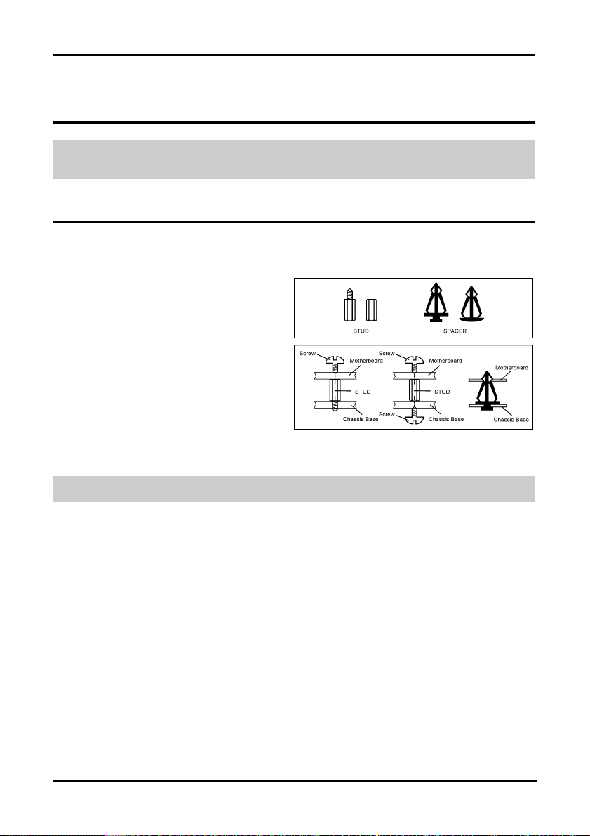
In principle, the best way to attach the board is to
use with studs. Only if you are unable to do this
should you attach the board with spacers. Line up
the holes on the board with the mounting holes on
the chassis. If the holes line up and there are
screw holes, you can attach the board with studs.
If the holes line up and there are only slots, you
can only attach with spacers. Take the tip of the
spacers and insert them into the slots. After doing
this to all the slots, you can slide the board into
position aligned with slots. After the board has been positioned, check to make sure everything is OK
before putting the chassis back on.
ATTENTION: To prevent shorting the PCB circuit, please REMOVE the metal studs or spacers if they
are already fastened on the chassis base and are without mounting-holes on the motherboard to align with.
User’s Manual
2-2 Chapter 2
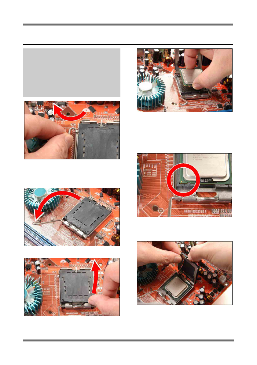
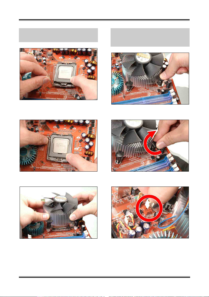
2-2. Install CPU, Heatsink and Fan Assembly
In order to protect the contact pins, please pay
attention to these notices:
1. A maximum 20 cycles of CPU installation
is recommended.
2. Never touch the contact pins with fingers
or any object.
3. Always put on the cap when the CPU is
not in use.
4. Use your right thumb and forefinger to
grasp the CPU package. Be sure to grasp on the
edge of the substrate, and face the Pin-1
indicator toward the bottom-left side. Aim at the
socket and place the CPU package vertical
down into the socket.
1. Place the board so as to let the lever hook
of the socket is on your left side. Use your left
thumb and forefinger to hold the lever hook,
pull it away from the retention tab.
2. Rotate the lever to fully open position.
3. Use your right thumb on the bottom-right
side of the load plate and lift it up to fully open
position.
5. Visually inspect if the CPU is seated well
into the socket. The alignment key must be
located in the notch of package.
6. Use your left hand to hold the load plate,
and use your right thumb to peel the cap off.
AG8 Series
Hardware Setup 2-3
The cap plays an important role in protecting
contact pins. In order to prevent bent pin, PUT
ON the cap after operation or testing.
7. Lower the plate onto the CPU package.
Engage the load lever while gently pressing
down the load plate.
8. Secure the lever with the hook under
retention tab.
For detailed information on how to install your
heatsink and fan assembly, please refer to the
instruction manual came packed with the
heatsink and fan assembly you bought.
10. Press each of the four fasteners down into
the mounting holes.
11. Rotate the fastener clock-wise to lock the
heatsink and fan assembly into position.
9. Place the heatsink and fan assembly onto
the socket. Align the four fasteners toward the
four mounting holes on the motherboard.
12. Attach the four-pin power plug from the
heatsink and fan assembly to the CPU FAN
connector.
User’s Manual
2-4 Chapter 2
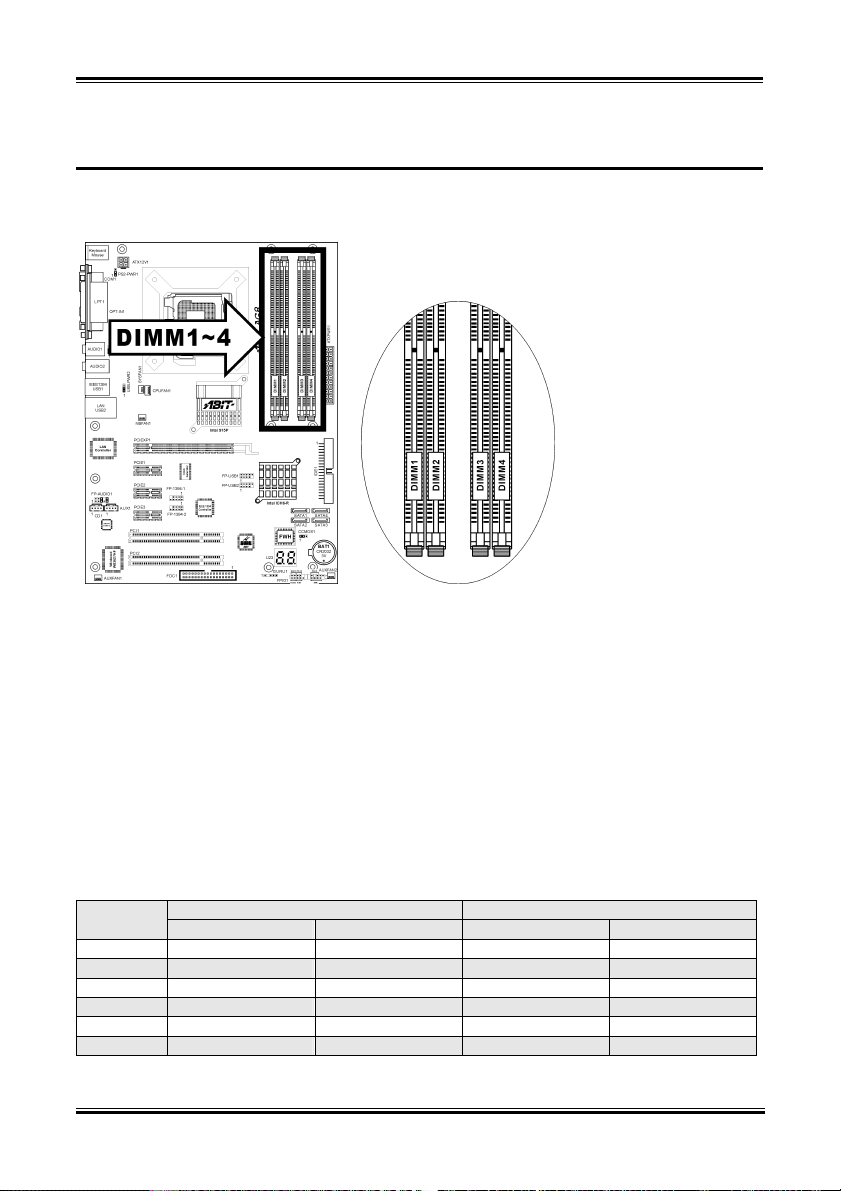
2-3. Install System Memory
The Intel 915P Express Chipset MCH memory interface is designed with Flex Memory Technology
supporting single-channel or dual-channel DDR memory configurations.
• To reach the optimum performance in dual-channel configurations, install identical DDR DIMM
pairs for each channel.
• Install DIMMs with the same CAS latency. To reach the optimum compatibility, obtain memory
modules from the same vendor.
• Due to chipset resource allocation, the system may detect less than 4GB of system memory in the
installation of four 1GB DDR memory modules.
• Due to chipset limitation, 128MB DIMM modules or double-sided x16 memory chips are not
supported.
There are several methods of different DDR configurations depending on how the DIMMs are populated
on each system memory channel:
• [Single Channel]: only one channel is populated.
Method
1 512MB - - 2 - 512MB - 3 - - 512MB 4 - - - 512MB
5 512MB 512MB - 6 - - 512MB 512MB
DIMM1 DIMM2 DIMM3 DIMM4
Channel A Channel B
AG8 Series
Hardware Setup 2-5
• [Dual Channel Asymmetric]: both channels are populated, but each channel has a different
amount of total memory. (Channel A≠Channel B)
Method
DIMM1 DIMM2 DIMM3 DIMM4
Channel A Channel B
1 512MB - 256MB 2 - 256MB - 512MB
3 512MB - - 256MB
4 - 256MB 512MB 5 256MB 256MB 256MB 6 256MB 256MB - 256MB
7 256MB - 256MB 256MB
8 - 256MB 256MB 256MB
9 256MB 256MB 512MB 512MB
10 256MB 256MB 256MB 512MB
• [Dual Channel Symmetric]: both channels are populated where each channel has the same amount
of total memory. (Channel A=Channel B)
Method
DIMM1 DIMM2 DIMM3 DIMM4
Channel A Channel B
1 512MB - 512MB 2 - 512MB - 512MB
3 512MB - - 512MB
4 - 512MB 512MB 5 256MB 256MB 512MB 6 256MB 256MB - 512MB
7 512MB - 256MB 256MB
8 - 512MB 256MB 256MB
9 512MB 256MB 512MB 256MB
10 256MB 512MB 256MB 512MB
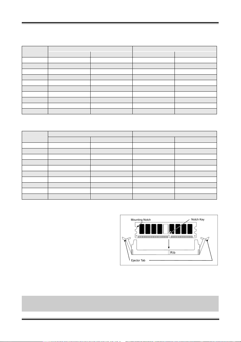
Power off the computer and unplug the AC power cord before installing or removing memory modules.
1. Locate the DIMM slot on the board.
2. Hold two edges of the DIMM module
carefully, keep away of touching its
connectors.
3. Align the notch key on the module with the
rib on the slot.
4. Firmly press the module into the slots until
the ejector tabs at both sides of the slot
automatically snaps into the mounting notch. Do not force the DIMM module in with extra force as
the DIMM module only fit in one direction.
5. To remove the DIMM modules, push the two ejector tabs on the slot outward simultaneously, and
then pull out the DIMM module.
ATTENTION: Static electricity can damage the electronic components of the computer or optional
boards. Before starting these procedures, ensure that you are discharged of static electricity by touching a
grounded metal object briefly.
User’s Manual
2-6 Chapter 2
2-4. Connectors, Headers and Switches
Here we will show you all of the connectors, headers and switches, and how to connect them. Please read
the entire section for necessary information before attempting to finish all the hardware installation inside
the computer chassis. A complete enlarged layout diagram is shown in Chapter 1 for all the position of
connectors and headers on the board that you may refer to.
WARNING: Always power off the computer and unplug the AC power cord before adding or removing
any peripheral or component. Failing to so may cause severe damage to your motherboard and/or
peripherals. Plug in the AC power cord only after you have carefully checked everything.
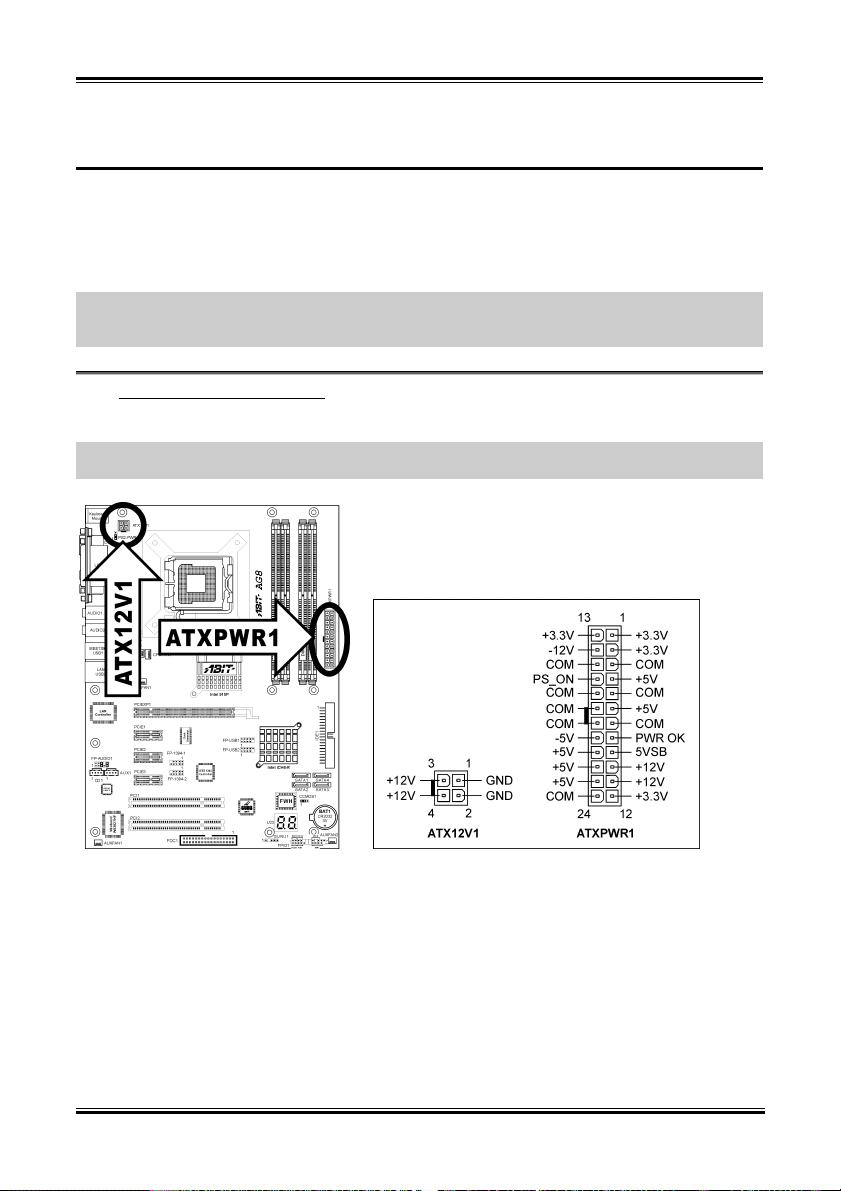
ATX Power Input Connectors
(1).
This motherboard provides two power connectors to connect power supplier.
NOTE: This 24-pin power connector “ATXPWR1” is compliant to the former 20-pin type. Pay attention
to the orientation when doing so (Pin-11, 12, 23, and 24 should be left un-connected).
AG8 Series
Hardware Setup 2-7
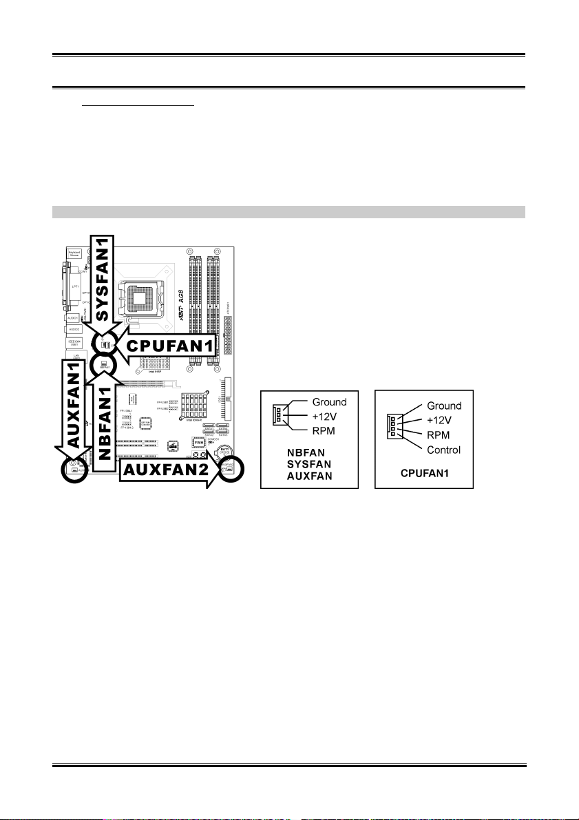
(2). FAN Power Connectors
These connectors each provide power to the cooling fans installed in your system.
• CPUFAN1: CPU Fan Power Connector
• NBFAN1: Chipset Fan Power Connector
• SYSFAN1: System Fan Power Connector
• AUXFAN1, AUXFAN2: Auxiliary Fan Power Connector
WARNING: These fan connectors are not jumpers. DO NOT place jumper caps on these connectors.
User’s Manual
2-8 Chapter 2
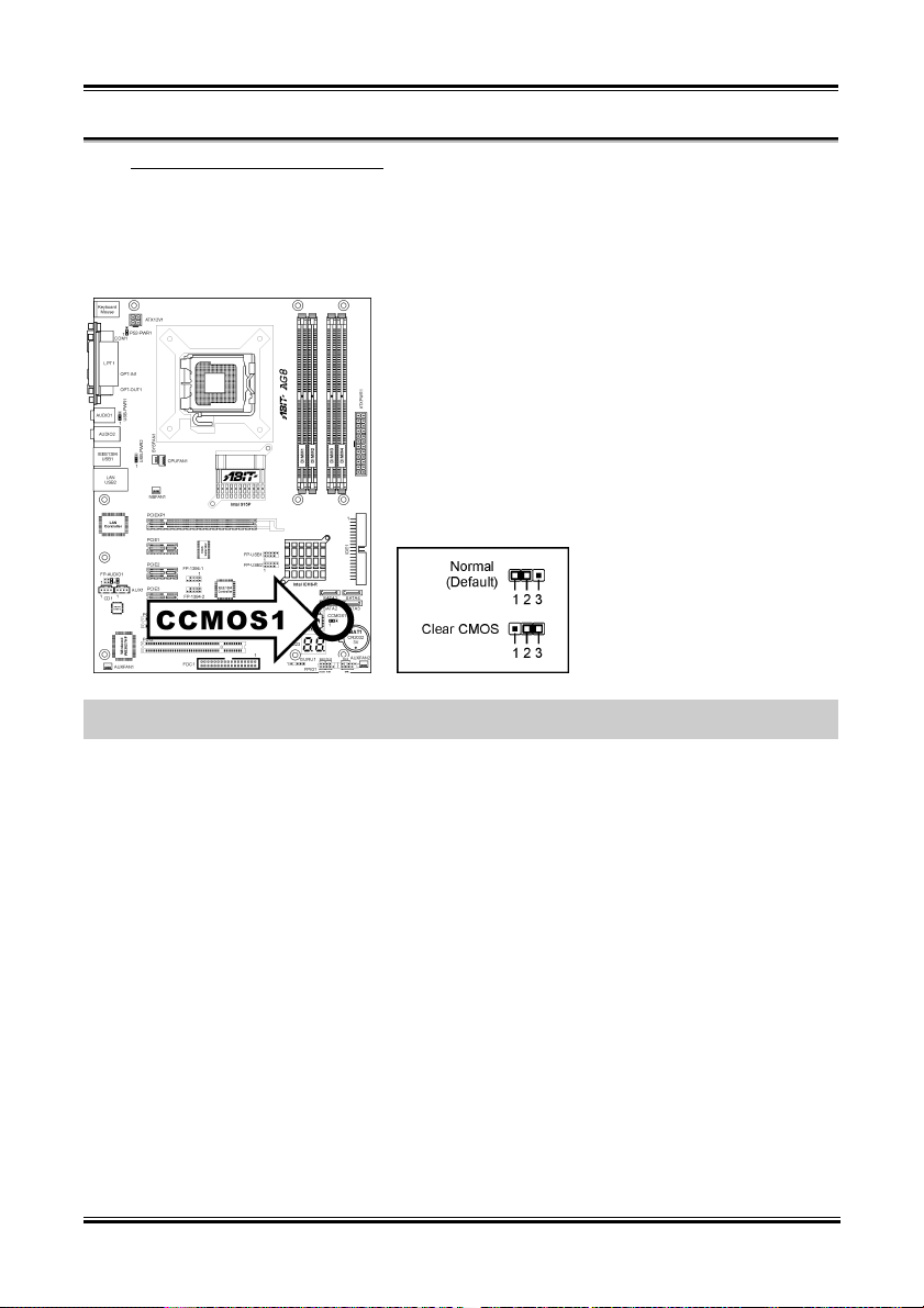
(3). CMOS Memory Clearing Header
This header uses a jumper cap to clear the CMOS memory.
• Pin 1-2 shorted (default): Normal operation.
• Pin 2-3 shorted: Clear CMOS memory.
WARNING: Turn the power off first (including the +5V standby power) before clearing the CMOS
memory. Failing to do so may cause your system to work abnormally or malfunction.
AG8 Series
Hardware Setup 2-9
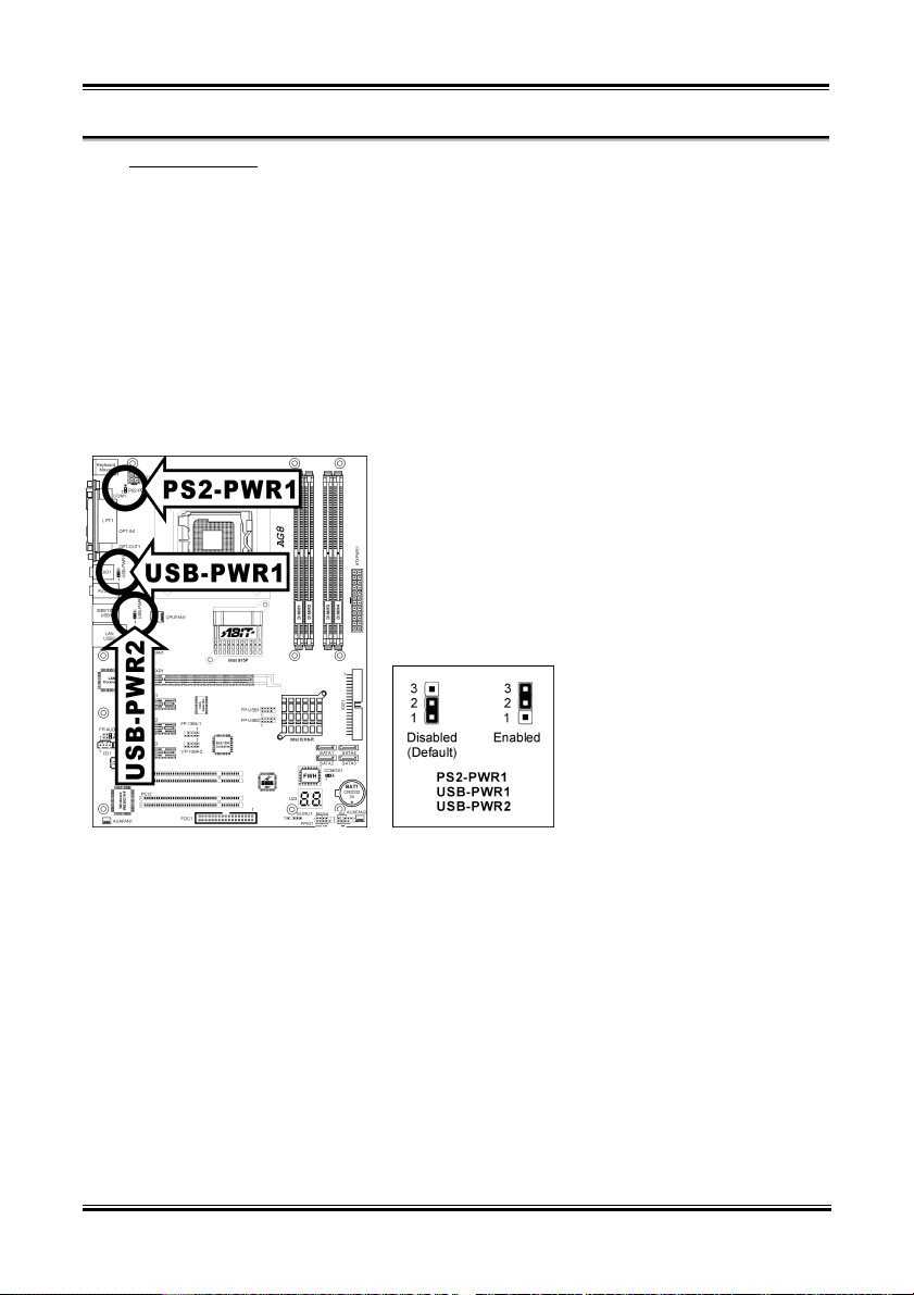
(4). Wake-up Header
These headers use a jumper cap to enable/disable the wake-up function.
• PS2-PWR1:
Pin 1-2 shorted (default): Disable wake-up function support at Keyboard/Mouse port.
Pin 2-3 shorted: Enable wake-up function support at Keyboard/Mouse port
• USB-PWR1:
Pin 1-2 shorted (default): Disable wake-up function support at USB1 port.
Pin 2-3 shorted: Enable wake-up function support at USB1 port.
• USB-PWR2:
Pin 1-2 shorted (default): Disable wake-up function support at USB2 port.
Pin 2-3 shorted: Enable wake-up function support at USB2 port
User’s Manual
2-10 Chapter 2
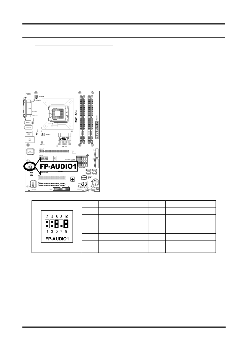
(5). Front Panel Audio Connection Header
This header provides the connection to audio connector at front panel.
• To use the audio connector at front panel, remove all the jumpers on this header, and then connect
to front panel by the extension cable provided with the chassis.
• To use the audio connector at rear panel, disconnect the extension cable, attach the jumpers back at
pin 5-6, and pin 9-10 (default setting).
Pin Pin Assignment Pin Pin Assignment
1 Audio Mic. 2 Ground
3 Audio Mic. Bias 4 VCC
Speaker Out Right
5
Channel
7 X 8 NC
Speaker Out Left
9
Channel
Speaker Out Right
6
Channel Return
Speaker Out Left
10
Channel Return
AG8 Series
Hardware Setup 2-11
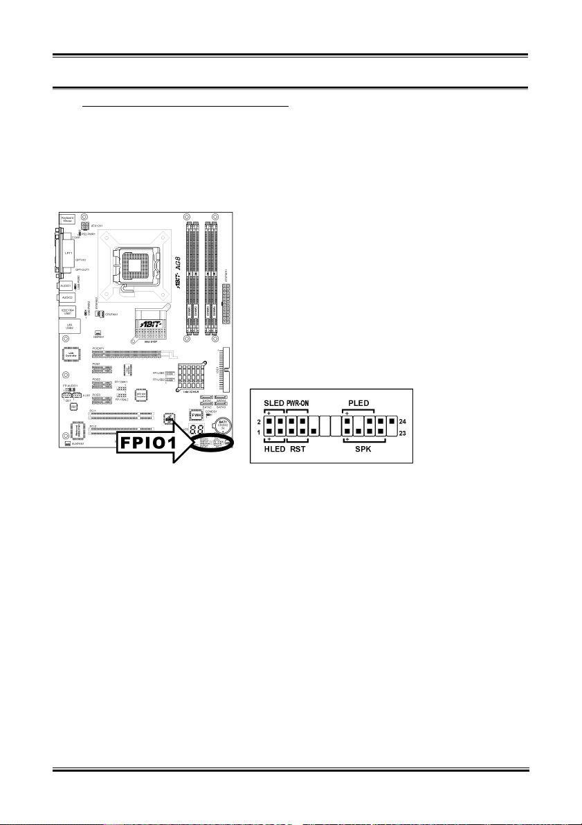
(6). Front Panel Switches & Indicators Headers
This header is used for connecting switches and LED indicators on the chassis front panel.
Watch the power LED pin position and orientation. The mark “+” align to the pin in the figure below
stands for positive polarity for the LED connection. Please pay attention to connect these headers. A
wrong orientation will only cause the LED not lighting, but a wrong connection of the switches could
cause system malfunction.
• HLED (Pin 1, 3):
Connects to the HDD LED cable of chassis front panel.
• RST (Pin 5, 7):
Connects to the Reset Switch cable of chassis front panel.
• SPK (Pin 15, 17, 19, 21):
Connects to the System Speaker cable of chassis.
• SLED (Pin 2, 4):
Connects to the Suspend LED cable (if there is one) of chassis front panel.
• PWR-ON (Pin 6, 8):
Connects to the Power Switch cable of chassis front panel.
• PLED (Pin 16, 18, 20):
Connects to the Power LED cable of chassis front panel.
User’s Manual
2-12 Chapter 2
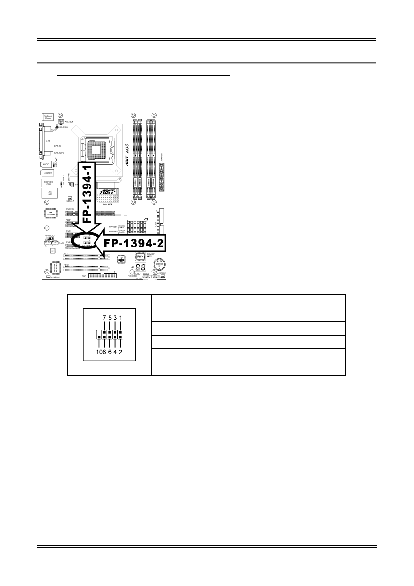
(7). Additional IEEE1394 Port Headers (For AG8 only)
These headers each provide one additional IEEE1394 port connection through an extension cable and
bracket.
Pin Pin Assignment Pin Pin Assignment
1 TPA0 + 2 TPA0 -
3 Ground 4 Ground
5 TPB0 + 6 TPB0 -
7 +12V 8 +12V
9 NC 10 Ground
AG8 Series
Hardware Setup 2-13
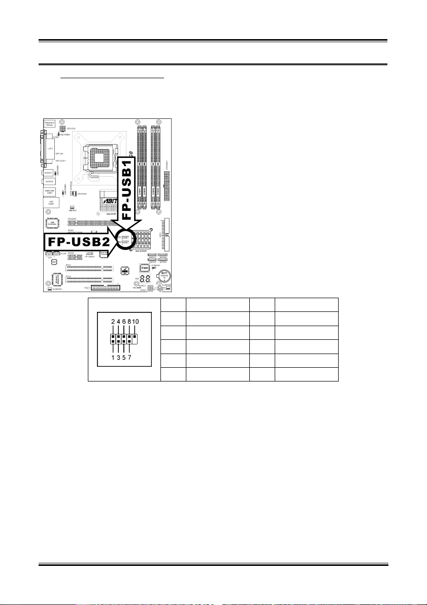
(8). Additional USB Port Headers
These headers each provide 2 additional USB 2.0 ports connection through an USB cable designed for
USB 2.0 specifications.
Pin Pin Assignment Pin Pin Assignment
1 VCC 2 VCC
3 Data0 - 4 Data1 -
5 Data0 + 6 Data1 +
7 Ground 8 Ground
9 NC 10 NC
User’s Manual
2-14 Chapter 2
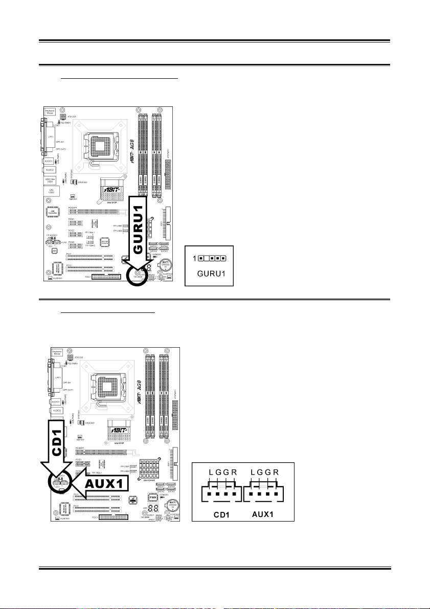
(9). GURU Clock Connection Header
This header is reserved for connecting ABIT’s exclusive GURU Clock.
(10). Internal Audio Connectors
These connectors connect to the audio output of internal CD-ROM drive or add-on card.
AG8 Series
Hardware Setup 2-15
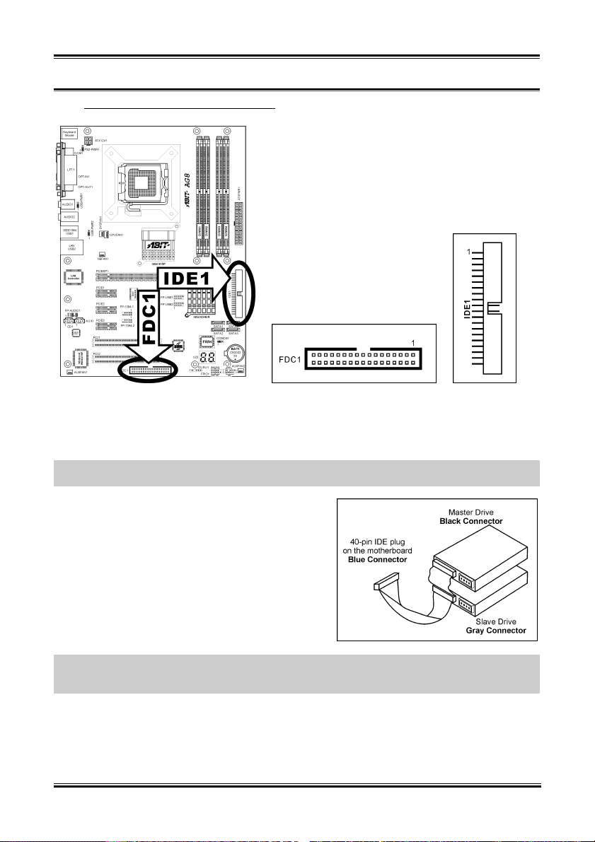
(11). Floppy and IDE Disk Drive Connectors
The FDC1 connector connects up to two floppy drives with a 34-wire, 2-connector floppy cable. Connect
the single end at the longer length of ribbon cable to the FDC1 on the board, the two connectors on the
other end to the floppy disk drives connector. Generally you need only one floppy disk drive in your
system.
NOTE: The red line on the ribbon cable must be aligned with pin-1 on both the FDC1 port and the floppy
connector.
Each of the IDE port connects up to two IDE drives at
Ultra ATA/100 mode by one 40-pin, 80-conductor, and
3-connector Ultra ATA/66 ribbon cables.
Connect the single end (blue connector) at the longer
length of ribbon cable to the IDE port of this board, the
other two ends (gray and black connector) at the shorter
length of the ribbon cable to the connectors of your hard
drives.
NOTE: Make sure to configure the “Master” and “Slave” relation before connecting two drives by one
single ribbon cable. The red line on the ribbon cable must be aligned with pin-1 on both the IDE port and
the hard-drive connector.
User’s Manual
2-16 Chapter 2
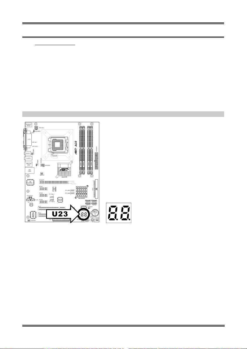
(12). POST Code Display
This is an LED device to display the “POST” Code, the acronym of Power On Self Test. The computer
will execute the POST action whenever you power on the computer. The POST process is controlled by
the BIOS. It is used to detect the status of the computer’s main components and peripherals. Each POST
Code corresponds to different checkpoints that are also defined by the BIOS in advance. For example,
“memory presence test” is an important checkpoint and its POST Code is “C1”. When the BIOS execute
any POST item, it will write the corresponding POST Code into the address 80h. If the POST passes, the
BIOS will process the next POST item and write the next POST Code into the address 80h. If the POST
fails, we can check the POST Code in address 80h to find out where the problem lies.
This LED device also displays the “POST” Code of AC2003, an “uGuru” chipset developed exclusively
by ABIT computer.
NOTE: The decimal point lights up when executing the AC2003 POST action.
See Appendix for both AWARD and AC2003 POST Code definition.
AG8 Series
 Loading...