


 Loading...
 FP-IN9 SLI
Motherboard
Socket 775
User’s Manual
For more information:
www.abit.com.tw
LGA775 ATX
NB: NVIDIA nForce 650i SLI
SB: NVIDIA nForce 430 SLI
MCP
1066MHz FSB
Dual DDR2 800
NVIDIA Gigabit LAN
4x SATA 3Gb/s
7.1-Channel HD Audio
Silent OTES™ Technology
FPIO LED Lighting
Quick Power & Reset Button
Vista HW Ready
Appendix QIG Multilingual Utility & Driver Setup BIOS Setup Hardware

FP-IN9 SLI
User’s Manual
English + Multilingual QIG
1st Edition, January 2007
Copyright and Warranty Notice
The information in this document is subject to change without notice and does not represent a commitment on part of the vendor, who assumes no liability or responsibility for any errors that may appear in this manual.
No warranty or representation, either expressed or implied, is made with respect to the quality, accuracy or fitness for any particular part of this document. In no event shall the manufacturer be liable for direct, indirect, special, incidental or consequential damages arising from any defect or error in this manual or product.
Product names appearing in this manual are for identification purpose only and trademarks and product names or brand names appearing in this document are the property of their respective owners.
This document contains materials protected under International Copyright Laws. All rights reserved. No part of this manual may be reproduced, transmitted or transcribed without the expressed written permission of the manufacturer and authors of this manual.
If you do not properly set the motherboard settings, causing the motherboard to malfunction or fail, we cannot guarantee any responsibility.
The Fatal1ty name, Fatal1ty logos and the Fatal1ty likeness are trademarks of Fatal1ty, Inc. All rights reserved. Built to Kill is a trademark of PWX, LLC.
© 2007 Universal ABIT Co., Ltd.
All other trademarks are the property of their respective owners.
ii |
FP-IN9 SLI |

Introduction
FATAL1TY STORY
Who knew that at age 19, I would be a World Champion PC gamer. When I was 13, I actually played competitive billiards in professional tournaments and won four or five games off guys who played at the highest level. I actually thought of making a career of it, but at that young age situations change rapidly. Because I’ve been blessed with great hand-eye coordination and a grasp of mathematics (an important element in video gaming) I gravitated to that activity.
GOING PRO
I started professional gaming in 1999 when I entered the CPL (Cyberathlete Professional League) tournament in Dallas and won $4,000 for coming in third place. Emerging as one of the top players in the United States, a company interested in sponsoring me flew me to Sweden to compete against the top 12 players in the world. I won 18 straight games, lost none, and took first place, becoming the number one ranked Quake III player in the world in the process. Two months later I followed that success by traveling to Dallas and defending my title as the world’s best Quake III player, winning the $40,000 grand prize. Since then I’ve traveled the globe to compete against the best in the world, winning prizes and acclaim, including the 2005 CPL World Tour Championship in New York City for a $150,000 first place finish.
LIVIN’ LARGE
Since my first big tournament wins, I have been a “Professional Cyberathlete”, traveling the world and livin’ large with lots of International media coverage on outlets such as MTV, ESPN and G4TV to name only a few. It's unreal - it's crazy. I’m living a dream by playing video games for a living. I’ve always been athletic and took sports like hockey and football very seriously, working out and training hard. This discipline helps me become a better gamer and my drive to be the best has opened the doors necessary to become a professional.
A DREAM
Now, another dream is being realized – building the ultimate gaming computer, made up of the best parts under my own brand. Quality hardware makes a huge difference in competitions…a couple more frames per second and everything gets really nice. It's all about getting the computer processing faster and allowing more fluid movement around the maps.
My vision for Fatal1ty hardware is to allow gamers to focus on the game without worrying about their equipment, something I’ve preached since I began competing. I don’t want to worry about my equipment. I want it to be there – over and done with - so I can focus on the game. I want it to be the fastest and most stable computer equipment on the face of the planet, so quality is what Fatal1ty brand products will represent.
FP-IN9 SLI |
iii |
Appendix QIG Multilingual Utility & Driver Setup BIOS Setup Hardware

FATAL1TY PARTNERS
This is just the beginning. We’re already in development for several new products, and I’m really grateful to all my Fatal1ty partners for helping make my dreams a reality.
I know there is a business side to all of this, but for me the true reward is making products that are so good I can win with them – and making them available to fellow gamers. Gaming is my life, and many fellow gamers around the world are also some of my best friends, so giving back to the gaming community is really important to me.
Johnathan “Fatal1ty” Wendel
iv |
FP-IN9 SLI |

Contents
1. Hardware Setup ............................................................... |
1-1 |
|
1.1 |
Specifications............................................................................... |
1-1 |
1.2 |
Motherboard Layout ..................................................................... |
1-2 |
1.3 |
Choosing a Computer Chassis ....................................................... |
1-3 |
1.4 |
Installing Motherboard ................................................................. |
1-3 |
1.5 |
Checking Jumper Settings............................................................. |
1-4 |
|
1.5.1 CMOS Memory Clearing Header and Backup Battery .............. |
1-4 |
1.6 |
Connecting Chassis Components ................................................... |
1-6 |
|
1.6.1 ATX Power Connectors......................................................... |
1-6 |
|
1.6.2 Front Panel Switches & Indicators Headers ........................... |
1-7 |
|
1.6.3 FAN Power Connectors ........................................................ |
1-8 |
1.7 |
Installing Hardware...................................................................... |
1-9 |
|
1.7.1 CPU Socket 775................................................................... |
1-9 |
|
1.7.2 DDR2 Memory Slots........................................................... |
1-11 |
|
1.7.3 PCI Express X16 Add-on Slots (Install Graphics Card) .......... |
1-13 |
1.8 |
Connecting Peripheral Devices .................................................... |
1-16 |
|
1.8.1 Floppy and IDE Disk Drive Connectors ................................ |
1-16 |
|
1.8.2 Serial ATA Connectors ....................................................... |
1-17 |
|
1.8.3 Additional USB 2.0 Port Headers......................................... |
1-18 |
|
1.8.4 Internal Audio Connectors.................................................. |
1-19 |
|
1.8.5 Front Panel Audio Connection Header ................................. |
1-19 |
|
1.8.6 PCI and PCI Express X1 Slot............................................... |
1-21 |
1.9 |
Onboard Indicators and Buttons.................................................. |
1-22 |
|
1.9.1 LED Indicators................................................................... |
1-22 |
|
1.9.2 Onboard Buttons ............................................................... |
1-22 |
1.10 Connecting Rear Panel I/O Devices ........................................... |
1-23 |
|
2. BIOS Setup....................................................................... |
2-1 |
||
2.1 |
SoftMenu Setup ........................................................................... |
2-2 |
|
2.2 |
Standard CMOS Features.............................................................. |
2-4 |
|
2.3 |
Advanced BIOS Features .............................................................. |
2-7 |
|
2.4 |
Advanced Chipset Features......................................................... |
2-10 |
|
2.5 |
Integrated Peripherals................................................................ |
2-12 |
|
2.6 |
Power Management Setup .......................................................... |
2-16 |
|
2.7 |
PnP/PCI Configurations .............................................................. |
2-18 |
|
2.8 |
PC Health Status ........................................................................ |
2-20 |
|
2.9 |
Load Fail-Safe Defaults............................................................... |
2-22 |
|
2.10 |
Load Optimized Defaults........................................................... |
2-22 |
|
2.11 |
Set Password ........................................................................... |
2-22 |
|
2.12 |
Save & Exit Setup..................................................................... |
2-22 |
|
2.13 |
Exit Without Saving .................................................................. |
2-22 |
|
|
|
|
|
FP-IN9 SLI |
|
v |
|
Appendix QIG Multilingual Utility & Driver Setup BIOS Setup Hardware
3. Driver & Utility ................................................................. |
3-1 |
|
3.1 |
CD-ROM AUTORUN ...................................................................... |
3-1 |
3.2 nVidia nForce Chipset Driver ......................................................... |
3-2 |
|
3.3 |
Realtek HD Audio Driver ............................................................... |
3-2 |
3.4 |
USB 2.0 Driver ............................................................................. |
3-3 |
3.5 |
ABIT EQ (The Hardware Doctor Utility).......................................... |
3-4 |
3.6 |
FlashMenu (BIOS Update Utility) ................................................... |
3-5 |
3.7 |
Build NVRaid Floppy Disk Under Windows Environment .................. |
3-6 |
3.8 |
Build A Driver Disk Under DOS Environment .................................. |
3-7 |
4. Multilingual Quick Installation Guide .............................. |
4-1 |
|
4.1 |
Français//Guide d'Installation Rapide............................................. |
4-1 |
4.2 |
Deutsch//Kurze Installationsanleitung............................................ |
4-2 |
4.3 |
Italiano//Guida all’installazione rapida ........................................... |
4-3 |
4.4 |
Español//Guía rápida de instalación............................................... |
4-4 |
4.5 |
Português//Guia de instalação rápida ............................................ |
4-5 |
4.6 |
Русский//Краткое руководство по установке .............................. |
4-6 |
4.7 |
Eesti//Kiirpaigaldusjuhend ............................................................ |
4-7 |
4.8 |
Latviski//Ātrās instalēšanas instrukcija........................................... |
4-8 |
4.9 |
Lietuvių//Trumpas instaliavimo vadovas ........................................ |
4-9 |
4.10 |
Polski//Instrukcja szybkiej instalacji........................................... |
4-10 |
4.11 |
Magyar//Gyorstelepítési útmutató.............................................. |
4-11 |
4.12 |
Türkçe//Hızlı Kurulum Kılavuzu.................................................. |
4-12 |
4.13 اللغة العربية//دليل التركيب السريع....................... |
4-13 |
|
4.14 |
فارسی// راﻩنمای نصب سریع............................................... |
4-14 |
4.15 |
// ...................................... |
4-15 |
4.16 |
// ....................................................... |
4-16 |
4.17 |
Bahasa Malaysia//Panduan Pemasangan Ringkas ....................... |
4-17 |
4.18 |
// ........................................................ |
4-18 |
4.19 |
................................................................................. |
4-19 |
4.19.1 ............................................................................... |
4-19 |
|
4.19.2 .................................................................. |
4-20 |
|
4.20 |
................................................................................. |
4-21 |
4.20.1 ............................................................................... |
4-21 |
|
4.20.2 .................................................................. |
4-22 |
|
5. Appendix .......................................................................... |
5-1 |
|
5.1 Troubleshooting (How to Get Technical Support?).......................... |
5-1 |
|
5.1.1 Q & A ................................................................................. |
5-1 |
|
5.1.2 Technical Support Form....................................................... |
5-4 |
|
5.1.3 Universal ABIT Contact Information...................................... |
5-5 |
|
|
|
|
|
|
|
vi |
|
FP-IN9 SLI |

1. Hardware Setup
1.1 Specifications
CPU
•Designed for Intel LGA775 processor with 1066MHz FSB
•Support Intel Core 2 Extreme, Core 2 Quad, Core 2 Duo, Pentium D, Pentium Dual Core, and Pentium 4 Processor
Chipset
•NB: NVIDIA nForce 650i SLI
•SB: NVIDIA nForce 430 SLI MCP
Memory
•4x 240-pin DIMM slots support maximum memory capacity up to 32GB
•Supports Dual Channel DDR2 800 Un-buffered Non-ECC memory
Graphics
•Two PCI-Express X16 slots support NVIDIA Scalable Link Interface
LAN
• NVIDIA Gigabit Ethernet
Audio
•Onboard 7.1-channel HD Audio CODEC
•Supports auto jack sensing and optical S/PDIF Out
Serial ATA
•4x SATA 3Gb/s supports NVIDIA MediaShield with SATA RAID 0, 1, 0+1, 5, and JBOD
Expansion Slots
•2x PCI-E X16 slots
•2x PCI-E X1 slots
•2x PCI slots
Internal I/O Connectors
•1x Floppy port
•2x Ultra ATA 133 IDE connectors
•4x SATA 3Gb/s connectors
•2x USB 2.0 headers
•1x FP-Audio header
•1x CD-In connector
Rear Panel I/O
•1x PS/2 Keyboard connector
•1x PS/2 Mouse connector
•1x S/PDIF Out connector
•1x 7.1-channel Audio connector
•4x USB 2.0 connectors
•1x RJ-45 Gigabit LAN connector
abit Engineered
•abit Silent OTES™ Technology
•FPIO LED Lighting
•Quick Power & Reset Button
RoHS
•100% Lead-free process and RoHS compliant
Miscellaneous
•ATX form factor (305mm x 245mm)
•Vista HW Ready
Specifications and information contained herein are subject to change without notice.
Setup Hardware
FP-IN9 SLI |
1-1 |

1.2 Motherboard Layout
1-2 |
FP-IN9 SLI |
1.3 Choosing a Computer Chassis
•Choose a chassis big enough to install this motherboard.
•As some features for this motherboard are implemented by cabling connectors on the motherboard to indicators and switches or buttons on the chassis, make sure your chassis supports all the features required.
•If there is a possibility of adopting some more hard drives, make sure your chassis has sufficient power and space for them.
•Most chassis have alternatives for I/O shield located at the rear panel. Make sure the I/O shield of the chassis matches the I/O port configuration of this motherboard. You can find an I/O shield specifically designed for this motherboard in its package.
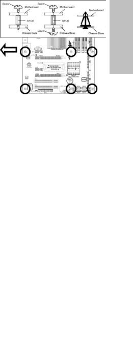
1.4 Installing Motherboard
Most computer chassis have a base with many mounting holes to allow the motherboard to be securely attached, and at the same time, prevent the system from short circuits. There are two ways to attach the motherboard to the chassis base: (1) with studs, or (2) with spacers.
Basically, the best way to attach the board is with studs. Only if you are unable to do this
should you attach the board with spacers. Line up the holes on the board with the mounting holes on the chassis. If the holes line up and there are screw holes, you can attach the board with studs. If the holes line up and there are only slots, you can only attach with spacers. Take the tip of the spacers and insert them into the slots. After doing this to all the slots, you can slide the board into position aligned with slots. After the board has been positioned, check to make sure everything is OK before putting the chassis back on.
Always power off the computer and unplug the AC power cord before adding or removing any peripheral or component. Failing to so may cause severe damage to your motherboard and/or peripherals. Plug in the AC power cord only after you have carefully checked everything.
To install this motherboard: |
|
|
1. |
Locate all the screw holes on the |
|
|
motherboard and the chassis base. |
|
2. |
Place all the studs or spacers needed on |
panel. |
|
the chassis base and have them tightened. |
|
|
|
|
3. |
Face the motherboard’s I/O ports toward |
rear |
|
the chassis’s rear panel. |
|
|
|
|
4. |
Line up all the motherboard’s screw holes |
chassis’s |
|
have them tightened. |
|
|
with those studs or spacers on the chassis. |
|
5. |
Install the motherboard with screws and |
|
|
To prevent shorting the PCB circuit, |
the |
|
please REMOVE the metal studs or |
Face |
|
spacers if they are already fastened |
|
|
on the chassis base and are without |
|
|
mounting-holes on the motherboard |
|
|
to align with. |
|
|
|
|
FP-IN9 SLI |
1-3 |
|
Setup Hardware
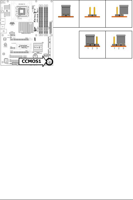
1.5 Checking Jumper Settings
•For a 2-pin jumper, plug the jumper cap on both pins will make it CLOSE (SHORT).
Remove the jumper cap, or plug it on either pin (reserved for future use) will
leave it at OPEN position. |
SHORT |
OPEN |
OPEN |
•For 3-pin jumper, pin 1~2 or pin 2~3 can be shorted by plugging the jumper cap in.
Pin 1~2 SHORT Pin 2~3 SHORT
1.5.1 CMOS Memory Clearing Header and Backup Battery
The time to clear the CMOS memory occurs when (a) the CMOS data becomes corrupted, (b) you forgot the supervisor or user password preset in the BIOS menu,
(c) you are unable to boot-up the system because the CPU ratio/clock was incorrectly set in the BIOS menu, or (d) whenever there is modification on the CPU or memory modules.
This header uses a jumper cap to clear the CMOS memory and have it reconfigured to the default values stored in BIOS.
•Pins 1 and 2 shorted (Default): Normal operation.
•Pins 2 and 3 shorted:
Clear CMOS memory.
To clear the CMOS memory and load in the default values:
1.Power off the system.
2.Set pin 2 and pin 3 shorted by the jumper cap. Wait for a few seconds. Set the jumper cap back to its default settings --- pin 1 and pin 2 shorted.
3.Power on the system.
4.For incorrect CPU ratio/clock settings in the BIOS, press <Del> key to enter the BIOS setup menu right after powering on system.
5.Set the CPU operating speed back to its default or an appropriate value.
6.Save and exit the BIOS setup menu.
1-4 |
FP-IN9 SLI |
CMOS Backup Battery:
An onboard battery saves the CMOS memory to keep the BIOS information stays on even after disconnected your system with power source. Nevertheless, this backup battery exhausts after some five years. Once the error message like “CMOS BATTERY HAS FAILED” or “CMOS checksum error” displays on monitor, this backup battery is no longer functional and has to be renewed.
To renew the backup battery:
1.Power off the system and disconnect with AC power source.
2.Remove the exhausted battery.
3.Insert a new CR2032 or equivalent battery. Pay attention to its polarity. The “+” side is its positive polarity.
4.Connect AC power source and power on the system.
5.Enter the BIOS setup menu. Reconfigure the setup parameters if necessary.
CAUTION:
Danger of explosion may arise if the battery is incorrectly renewed.
Renew only with the same or equivalent type recommended by the battery manufacturer.
Dispose of used batteries according to the battery manufacturer’s instructions.
Setup Hardware
FP-IN9 SLI |
1-5 |
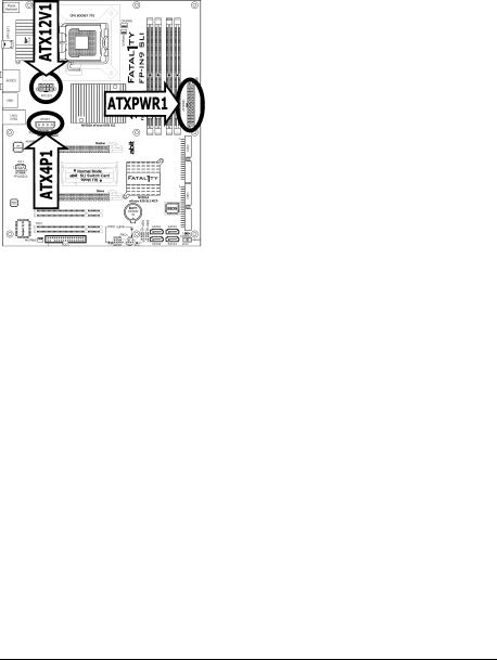
1.6 Connecting Chassis Components
1.6.1 ATX Power Connectors
These connectors provide the connection from an ATX power supply. As the plugs from the power supply fit in only one orientation, find the correct one and push firmly down into these connectors.
ATXPWR1: ATX 24-Pin Power Connector
The power supply with 20-pin or 24-pin cables can both be connected to this 24-pin connector. Connect from pin-1 for either type. However, a 20-pin power supply may cause the system unstable or even unbootable for the sake of insufficient electricity. A minimum power of 300W or higher is recommended.
ATX12V1: ATX 12V 8-Pin Power Connector
This connector supplies power to CPU. The system will not start without connecting power to this one.
ATX4P1: Auxiliary 12V Power Connector
This connector provides an auxiliary power source for devices added on PCI Express slots.
1-6 |
FP-IN9 SLI |

1.6.2 Front Panel Switches & Indicators Headers
This header is used for connecting switches and LED indicators on the chassis front panel.
Watch the power LED pin position and orientation. The mark “+” align to the pin in the figure below stands for positive polarity for the LED connection. Please pay attention when connecting these headers. A wrong orientation will only result in the LED not lighting, but a wrong connection of the switches could cause system malfunction.
•HLED (Pin 1, 3):
Connects to the HDD LED cable of chassis front panel.
•RST (Pin 5, 7):
Connects to the Reset Switch cable of chassis front panel.
•SPKR (Pin 13, 15, 17, 19):
Connects to the System Speaker cable of chassis.
•SLED (Pin 2, 4):
Connects to the Suspend LED cable (if there is one) of chassis front panel.
•PWR (Pin 6, 8):
Connects to the Power Switch cable of chassis front panel.
•PLED (Pin 16, 18, 20):
Connects to the Power LED cable of chassis front panel.
FP-IN9 SLI |
1-7 |
Setup Hardware
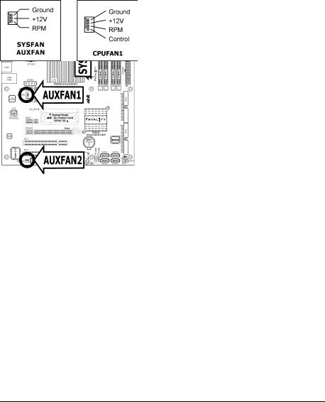
1.6.3 FAN Power Connectors
These connectors each provide power to the cooling fans installed in your system.
•CPUFAN1: CPU Fan Power Connector
•SYSFAN1: System Fan Power Connector
•AUXFAN1~2: Auxiliary Fan Power Connector
These fan connectors are not jumpers. DO NOT place jumper caps on these connectors.
1-8 |
FP-IN9 SLI |
1.7 Installing Hardware
DO NOT scratch the motherboard when installing hardware. An accidental scratch of a tiny surface-mount component may seriously damage the motherboard.
In order to protect the contact pins, please pay attention to these notices:
1.A maximum 20 cycles of CPU installation is recommended.
2.Never touch the contact pins with fingers or any object.
3.Always put on the cap when the CPU is not in use.
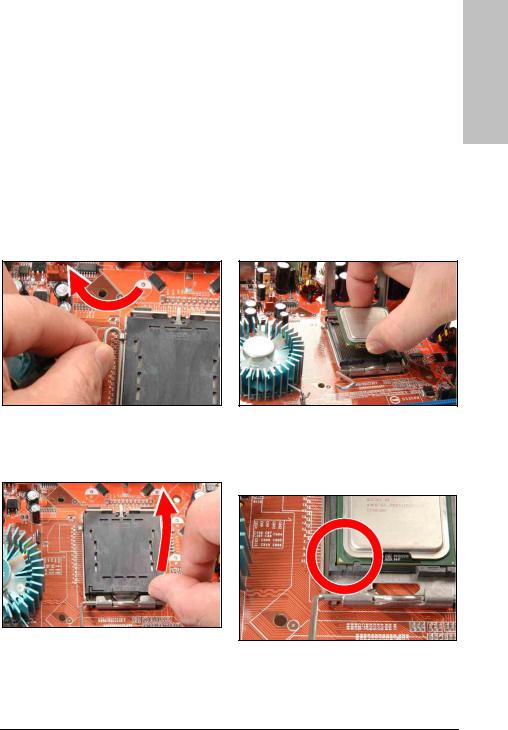
1.7.1 CPU Socket 775
The installation procedures vary with different types of CPU fan-and-heatsink assembly. The one shown here is served for demo only. For detailed information on how to install the one you bought, refer to its installation guidelines.
Setup Hardware
1. Place the board so that the lever-hook of the socket is on your left side. Use your left thumb and forefinger to hold the lever hook, pull it away from the retention tab. Rotate the lever to fully open position.
2. Use your right-thumb to raise the load plate. Lift it up to fully open position.
3. Use your right thumb and forefinger to grasp the CPU package. Be sure to grasp on the edge of the substrate, and face the Pin-1 indicator toward the bottom-left side. Aim at the socket and place the CPU package vertical down into the socket.
4. Visually inspect if the CPU is seated well into the socket. The alignment key must be located in the notch of package.
FP-IN9 SLI |
1-9 |
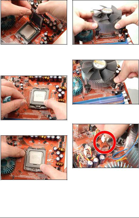
5. Use your left hand to hold the load plate, and use your right thumb to peel the cap off.
The cap plays an important role in protecting contact pins. In order to prevent bent pin, PUT ON the cap after operation or testing.
6. Lower the plate onto the CPU package. Engage the load lever while gently pressing down the load plate.
7. Secure the lever with the hook under retention tab.
8. Place the heatsink and fan assembly onto the socket. Align the four fasteners toward the four mounting holes on the motherboard.
9. Press each of the four fasteners down into the mounting holes. Rotate the fastener clock-wise to lock the heatsink and fan assembly into position.
10. Attach the four-pin power plug from the heatsink and fan assembly to the CPU FAN connector.
A higher fan speed will be helpful for better airflow and heat-dissipation. Nevertheless, stay alert to not touch any heatsink since a high temperature generated by the working system is still possible.
1-10 |
FP-IN9 SLI |
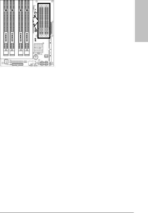
1.7.2 DDR2 Memory Slots
Setup Hardware
To reach the performance of Dual Channel DDR2, the following rules must be obeyed:
•For a 2-DIMM dual-channel installation:
Populate DIMM modules of the same type and size on slots [DIMM1]+[DIMM3], or slots [DIMM2]+[DIMM4].
•For a 4-DIMM dual-channel installation:
Populate 2 DIMM modules of the same type and size on slots [DIMM1]+[DIMM3], and another 2 DIMM modules of the same type and size on slots [DIMM2]+[DIMM4].
[DIMM1] and [DIMM3] slots are made of the same color. [DIMM2] and [DIMM4] are made of another same color.
Usually there is no hardware or BIOS setup required after adding or removing memory modules, but you will have to clear the CMOS memory first if any memory module related problem occurs.
FP-IN9 SLI |
1-11 |
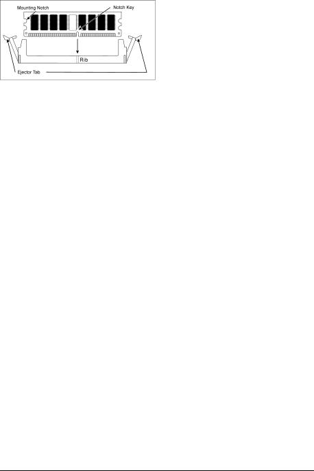
To install system memory:
1.Power off the computer and unplug the AC power cord before installing or removing memory modules.
2.Locate the DIMM slot on the board.
3.Hold two edges of the DIMM module carefully, keep away from touching its connectors.
4.Align the notch key on the module with the rib on the slot.
5.Firmly press the module into the slots until the ejector tabs at both sides of the slot automatically snap into the mounting notch. Do not force the DIMM module in with extra force as the DIMM module only fits in one direction.
6.To remove the DIMM modules, push the two ejector tabs on the slot outward simultaneously, and then pull out the DIMM module.
Static electricity can damage the electronic components of the computer or optional boards. Before starting these procedures, ensure that you are discharged of static electricity by touching a grounded metal object briefly.
1-12 |
FP-IN9 SLI |
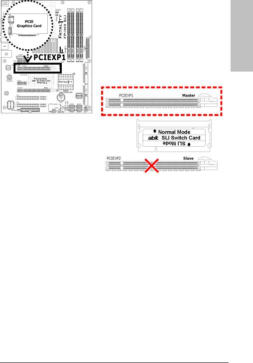
1.7.3 PCI Express X16 Add-on Slots (Install Graphics Card)
These slots support the connections of graphics cards that comply with PCI Express specifications. This motherboard provides two PCI-Express X16 slots:
One PCIE graphics card installation (Normal Mode):
Insert your PCIE graphics card into [PCIEXP1] (Master) slot.
There will be no video output in the Normal Mode for one PCIE graphics card installation into [PCIEXP2] (Slave) slot.
Never remove or lose the “SLI Switch Card”, as this card still works in this Normal Mode.
Setup Hardware
FP-IN9 SLI |
1-13 |
Two PCIE graphics cards installation (SLI Mode):
To install two SLI-ready graphics cards under SLI Mode, you will need to:
•Prepare two identical NVIDIA certified, SLI-ready PCI Express X16 graphics cards (the same model from the same manufacturer).
•Make sure the graphics card driver supports the NVIDIA SLI technology. Download the latest driver form NVIDIA website (www.nvidia.com).
•Make sure your power supply unit is sufficient to provide the minimum power required.
The following illustration is served for DEMO only. All the devices, including the motherboard, the graphics cards, the SLI Bridge Connector, or the SLI bracket, may not be exactly the same type, shape, or model as the one you have at hand.
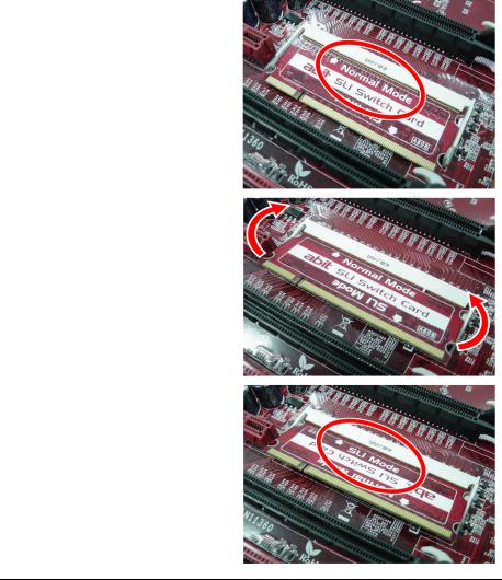
1.There is one “SLI Switch Card” factory-mounted on this motherboard. This card served as a switch between “Normal” and “SLI” video output mode. The default setting is “Normal” mode for single graphics card.
As shown in this photo, the card is factory-mounted with its “Normal Mode” side toward the retention slot base.
2.To change from “Normal” to “SLI” Mode, you will have to reverse the direction of the “SLI Switch Card”: Simultaneously pull open both the retention arms that hold the card in position. The card itself will spring away from the retention slot. Take it out gently by holding its edges, and keep away from touching the connectors (Golden Fingers).
3.Reverse the card direction so as to have the “SLI Mode” side toward the retention slot base. Insert the card into the bottom of the base.
1-14 |
FP-IN9 SLI |
4.Push the card down into the retention slot till both the retention arms firmly hold the card into position. Also, keep away from touching the connectors (Golden Fingers).
5.Insert two identical SLI-ready graphics cards into both [PCIEXP1] (Master) and [PCIEXP2] (Slave) slots.
6.Bridge connecting two graphics cards with the “SLI Connector Card” (fit in both directions). Insert and secure the SLI supporting bracket.
Refer to the instruction of your SLI-ready graphics cards on how to select Normal or SLI video output mode. For SLI mode, connect your monitor to the SLI-ready graphics card installed on the [PCIEXP1] (Master) slot only.
Setup Hardware
FP-IN9 SLI |
1-15 |
1.8 Connecting Peripheral Devices
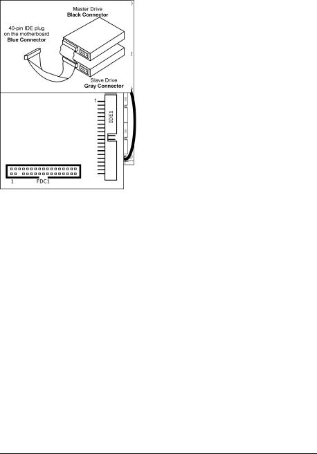
1.8.1 Floppy and IDE Disk Drive Connectors
The FDC1 connector connects up to two floppy drives with a 34-wire, 2-connector floppy cable. Connect the single end at the longer length of ribbon cable to the FDC1 on the board, the two connectors on the other end to the floppy disk drives connector. Generally you need only one floppy disk drive in your system.
The red line on the ribbon cable must be aligned with pin-1 on both the FDC1 port and the floppy connector.
Each of the IDE port connects up to two IDE drives at Ultra ATA/100 mode by one 40-pin, 80-conductor, and 3-connector Ultra ATA/66 ribbon cables.
Connect the single end (blue connector) at the longer length of ribbon cable to the IDE port of this board, the other two ends (gray and black connector) at the shorter length of the ribbon cable to the connectors of your hard drives.
Make sure to configure the “Master” and “Slave” relation before connecting two drives by one single ribbon cable. The red line on the ribbon cable must be aligned with pin-1 on both the IDE port and the hard-drive connector.
1-16 |
FP-IN9 SLI |
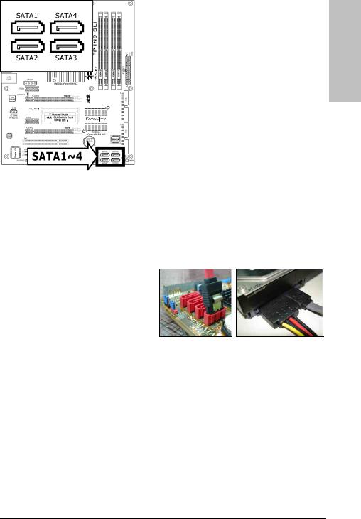
1.8.2 Serial ATA Connectors
Each SATA connector serves as one single channel to connect one SATA device by SATA cable.
The RAID 0/1/0+1/5/JBOD configuration is also possible by the combination of disk arrays through these SATA connectors:
To connect SATA device:
1.Attach either end of the signal cable to the SATA connector on motherboard. Attach the other end to the SATA device.
2.Attach the SATA power cable to the SATA device and connect the other end from the power supply.
The motherboard in this photo is served for DEMO only, and may not be the same type or model as the one described in this user’s manual.
Setup Hardware
FP-IN9 SLI |
1-17 |
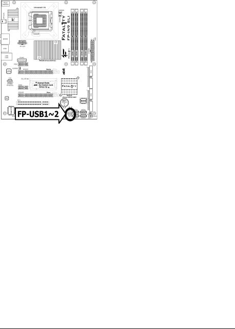
1.8.3 Additional USB 2.0 Port Headers
Each header supports 2x additional USB 2.0 ports by connecting bracket or cable to the rear I/O panel or the front-mounted USB ports of your chassis.
Pin |
Pin Assignment |
Pin |
Pin Assignment |
|
|
|
|
1 |
VCC |
2 |
VCC |
3 |
Data0 - |
4 |
Data1 - |
5 |
Data0 + |
6 |
Data1 + |
7 |
Ground |
8 |
Ground |
|
|
|
|
|
|
10 |
NC |
|
|
|
|
Make sure the connecting cable bears the same pin assignment.
1-18 |
FP-IN9 SLI |
1.8.4 Internal Audio Connectors
This connector connects to the audio output of internal CD-ROM drive or add-on card.
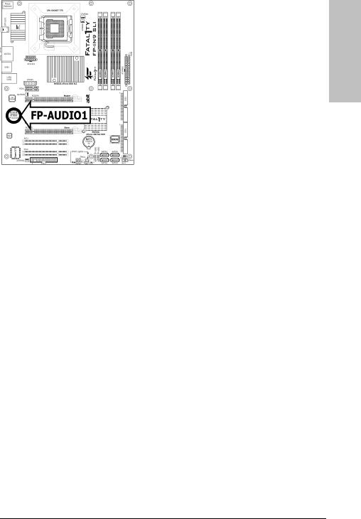
1.8.5 Front Panel Audio Connection Header
This header provides the front panel connection for HD (High Definition) Audio, yet for AC’97 Audio CODEC connection, you must carefully check the pin assignment before connecting from the front panel module. An incorrect connection may cause malfunction or even damage the motherboard.
Please do not connect the “Ground” cable or “USB VCC” cable from the front panel module to the Pin 4 “AVCC” of this header.
Setup Hardware
Pin |
Pin Assignment |
|
(HD AUDIO) |
|
|
1 |
MIC2 L |
|
|
2 |
AGND |
|
|
3 |
MIC2 R |
|
|
4 |
AVCC |
|
|
5 |
FRO-R |
|
|
6 |
MIC2_JD |
|
|
7 |
F_IO_SEN |
|
|
9 |
FRO-L |
|
|
10 |
LINE2_JD |
|
|
Pin |
Pin Assignment |
|
(AC’97 AUDIO) |
|
|
1 |
MIC In |
|
|
2 |
GND |
|
|
3 |
MIC Power |
|
|
4 |
NC |
|
|
5 |
Line Out (R) |
|
|
6 |
NC |
|
|
7 |
NC |
|
|
9 |
Line Out (L) |
|
|
10 |
NC |
|
|
FP-IN9 SLI |
1-19 |
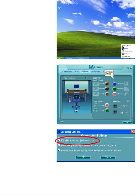
Driver Configuration for AC’97 audio connection:
The audio driver is originally configured to support HD Audio. For AC’97 audio connection, you may:
1.Right-click the “Realtek HD
Audio Manager” icon  in system tray.
2.Click “Audio I/O” tab, and then click “Connector Settings”.
3.Click “Disabled front panel jack detection”, and then click “OK” to confirm.
1-20 |
FP-IN9 SLI |

1.8.6 PCI and PCI Express X1 Slot
Install PCI Express X1 cards into slots “PCIE1” and/or “PCIE2”. Install PCI cards into slots “PCI1” and/or “PCI2”.
Setup Hardware
FP-IN9 SLI |
1-21 |
Loading...