


3
WIBGET™ Heat Stress Monitor RSS-214
User Instructions
(Keep these User Instructions for reference)
Moniteur de stress thermique RSS-214 WIBGET™
Directives d’utilisation
(Conserver ces directives à titre de référence)
Monitor de estrés térmico WIBGET™ RSS-214
Instrucciones de uso
(Conserve estas Instrucciones de uso para referencia futura.)
WIBGET™ RSS-214 Monitor de Sobrecarga Térmica
Instruções de Uso
(Guarde estas Instruções de Uso para referência futura)
FUNCTION
VIEW
time base
|
OUT WBGT |
MONITOR / log |
°F |
|
|
start |
|
SELECT |
|
°C/°F
TABLE OF CONTENTS
GENERAL SAFETY INFORMATION |
4 |
Intended Use |
4 |
List of Warnings and Cautions |
4 |
USE INSTRUCTIONS AND LIMITATIONS |
5 |
General Description |
5 |
SPECIFICATIONS |
6 |
WBGT |
7 |
SETUP |
7 |
Sensor Installation |
7 |
Wet Bulb Preparation |
7 |
Location and Environment |
7 |
OPERATING INSTRUCTIONS |
7 |
Power On/Off |
8 |
Self-Diagnostics |
8 |
Monitor Mode |
8 |
Analog/Recorder Output (monitor mode only) |
8 |
DATA LOGGING (Optional) |
8 |
Setting and Viewing Calendar/Clock |
9 |
Log Mode |
9 |
Demand Logging |
9 |
View While Logging |
9 |
Exit Data Logging |
9 |
Exit Data Logging Mode |
|
and Return to Monitor Mode |
9 |
DOWNLOADING DATA |
9 |
System Requirements |
9 |
Installing WIBGET Heat Stress Monitor Software |
9 |
Downloading Data |
10 |
MAINTENANCE |
11 |
Wet Bulb |
11 |
Wick Replacement |
11 |
Water Treatment |
11 |
Cleaning |
11 |
Storage |
11 |
BATTERY |
11 |
Charging |
11 |
Replacement |
11 |
CALIBRATION |
11 |
TROUBLESHOOTING |
12 |
PRODUCTS, ACCESSORIES AND PARTS |
12 |
WARRANTY |
13 |
FOR MORE INFORMATION |
13 |

GENERAL SAFETY INFORMATION
Intended Use
The 3M™ WIBGET™ Heat Stress Monitor RSS-214 is designed to measure environmental factors that can contribute to heat stress.
List of Warnings and Cautions within these User Instructions
 WARNING
This monitor helps to measure certain environmental factors that can contribute to heat stress. Misuse may result in sickness or death. For proper use, see supervisor or User Instructions, or call 3M in U.S.A., 1-800-243-4630. In Canada, call Technical Service at 1-800-267-4414.
Each person using this equipment must read and understand the information in these User Instructions. Use of this equipment by untrained or unqualified persons, or use that is not in accordance with these User Instructions, may adversely affect product performance and result in sickness or death.
Use only for monitoring environmental factors which the sensors and instrument are designed to monitor. Failure to do so may adversely affect product performance and result in sickness or death. For proper use, see supervisor or User Instructions, or call 3M in U.S.A., 1-800-243-4630. In Canada, call Technical Service at 1-800-267-4414.
Each time the unit is turned on, it performs a self-test. If the self-test fails, or an error code is displayed, do not use. Doing so may adversely affect product performance and result in sickness or death.
The RSS-214DL RS 232 serial data output port must be used in a non-hazardous area only. Using the data output port is not an intrinsically safe operation. Failure to do so may result in sickness or death.
Never alter or modify this instrument. Substitution of components may impair intrinsic safety. Doing so may adversely affect product performance and result in sickness or death. Repair or replace parts only with the 3M components approved for this unit. Failure to do so may adversely affect product performance and result in sickness or death.
Battery must be replaced in a non-hazardous area only. Battery replacement is not an intrinsically safe operation. Use only approved battery. Failure to do so may result in sickness or death.
Only charge the instrument in non-hazardous areas using a 3M battery charger (AC adapter). Battery charging and operating with AC adapter is not an intrinsically safe operation. Do not attempt to charge alkaline batteries. Doing so may adversely affect product performance and result in sickness or death.
CAUTION
Do not twist sensors once inserted into the base unit. Doing so may damage the sensor or sensor connector. The wet bulb wick must remain wet during operation to help maintain the accuracy of the sensor.
Keep all connectors clean and dry. If a connector becomes wet, it must be thoroughly dried prior to instrument usage. Condition of the sensor receptacles may be tested by removing all sensors, turning the unit on and checking that all functions read 0.0 ± 0.3 °C or 32.0 ± 0.5 °F. If these are not the readings, do not use until the reason has been determined and corrected.
Do not expose dry bulb (DB) to temperatures above 65 °C (150 °F). This may damage the base unit. To monitor environments above 65 °C (150 °F), use a remote sensor set accessory and relocate the base unit to a cooler area.
Avoid the use of harsh cleaning materials, abrasives and other organic solvents. Such materials may permanently scratch the surfaces and damage the display window, labels, or monitor housing.
Observe proper polarity when inserting the battery. Polarity is marked on the inside of the battery compartment.
This instrument may contain a nickel metal hydride (NiMH) battery. Dispose of battery in accordance with local regulations.
USE INSTRUCTIONS AND LIMITATIONS
Important
Before use, each person using this equipment must read and understand these User Instructions. Keep these User Instructions for reference.
General Description
These User Instructions apply to the 3M™ WIBGET Heat Stress Monitor RSS-214. It is a hand held microprocessor-based Wet Bulb Globe Thermometer designed to measure certain environmental factors that can contribute to heat stress. An internal microprocessor controls the indication and response to the signals received from the sensors mounted on top of the unit. When turned on it continuously monitors the ambient air.
The WIBGET monitor is a battery-powered unit utilizing a 9-volt rechargeable nickel metal hydride (NiMH) battery or replaceable 9-volt non-rechargeable alkaline battery. It is designed to be intrinsically safe when powered by batteries. The WIBGET monitor is CSA certified intrinsically safe for Class I, Div. I, Groups A,B,C,and D Hazardous Locations.
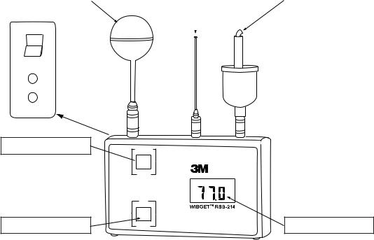
The components of the WIBGET monitor are assembled in a plastic housing 3.75 H x 6.2 W x 1.75 D in. (Fig. 1). Located on the front face of the unit are the display (LCD) and the FUNCTION and SELECT buttons. On the left side of the unit are the On/Off switch, analog output, and charger jacks. On top of the unit are the sensor connector pins for the Globe (GT), Dry Bulb (DB), and Wet Bulb (WB) sensors. On the back of the unit is a label containing the intrinsic safety information and serial number.
Globe Sensor |
|
Dry Bulb Sensor |
|
Wet Bulb Sensor |
|
|
|
|
|
|
|
|
|
|
|
|
|
ON
OFF
Analog Output 0-1V
Charger 12vdc
Function Button
Select Button
FUNCTION
 VIEW
VIEW
time base
OUT |
WBGT |
MONITOR / log |
°F |
|
|
start |
|
SELECT |
|
°C/°F |
LCD Display |
Fig. 1

SPECIFICATIONS
Size |
6.2 x 3.75 x 1.75 (inches), 15.8 x 9.5 x 4.5 (cm) |
|
Height with sensors 8.5 (inches), 21.6 (cm) |
|
|
Weight |
12 oz. (350g) |
|
|
Readout |
Direct read LCD |
|
|
Readings |
· Indoor Wet Bulb Globe Temperature (IN WBGT) |
|
· Outdoor Wet Bulb Globe Temperature (OUT WBGT) |
|
· Wet Bulb (WB) |
|
· Dry Bulb (DB) |
|
· Globe Temperature (GT) |
|
|
WBGT Value Calculations |
· WBGT (outdoor) = 0.7 WB + 0.2 GT + 0.1DB |
|
· WBGT (indoor) = 0.7 WB + 0.3 GT |
|
WB = Wet Bulb; GT = Vernon Globe Equivalent Temperature; DB = Dry Bulb) |
|
|
Reading Resolution |
0.1 °C/0.1 °F |
|
|
Calibrated Ranges |
25 °C (77 °F); 45 °C (113°F); 60 °C (140 °F) |
|
|
Response |
· Electronics < 3 seconds (provided sensors are acclimatized) |
|
· Sensors (90% accuracy) <2.2 minutes |
|
· Sensors (95% accuracy) <4.5 minutes |
|
|
Sensors |
· Globe Temperature (GT) - Construction provides characteristics identical to 6" Vernon Globe |
|
· Dry Bulb (DB) - Ambient air temperature |
|
· Wet Bulb (WB) - Wick-covered sensor with reservoir, wetted with deionized or distilled water |
|
|
Intrinsic Safety* |
CSA – Std C22.2 No. 157-M1987, EXIA LR84375 |
|
|
Approved Batteries/Power Source |
· Rechargeable 9-volt NiMH battery (Varta™ V7/8H) |
|
· 9-volt non-rechargeable alkaline battery (Duracell® MN1604 or Eveready® 522) |
|
· Operate continuously on 3M supplied charger (AC adapter) |
|
|
Battery Life |
Approximately 17 hours – continuous operation |
|
|
Battery Recharge Time (NiMH) |
Approximately 14 hours |
|
|
Operating Temperature Range |
0 °C to 65 °C (32 °F to 149 °F) |
|
|
Instrument Storage Temperature |
-25 °C to 65 °C (-13 °F to 140 °F) |
|
|
Accuracy |
+/-0.4 °C (+/-0.7 °F) of actual temperature at 25.0 °C, 45 °C and 60.0 °C (77.0 °F, 113 °F, 140.0 °F) |
|
@ air speed = 180 fpm minimum. |
|
|
Analog/Recorder Output |
10mV/ °C ± 1mV |
|
|
Warranty |
1 year (See WARRANTY section) |
|
|
Data Logger (Optional) |
|
|
|
Data Logger |
Optional add-in Data Logger/RS232C Port accessory |
|
|
Memory |
Nonvolatile |
|
|
Data Logging Storage |
511 records |
|
|
Data Logging output |
Record number, date, time, WB, DB, GT, In-WBGT, Out-WBGT |
|
|
Data Logging Interval |
Manually or preselected intervals of 0.5, 1, 2, 5, 6, 10, 20, or 30 minutes |
|
|
*The RSS-214 and RSS-214DL are intrinsically safe when used with the DB, WB, and GT sensors only.
Varta is a trademark of Spectrum Brands. Duracell is a registered trademark of Proctor & Gamble. Eveready is a registered trademark of Eveready.
WBGT
According to the American Conference of Governmental Industrial Hygienists (ACGIH), the Wet Bulb Globe Temperature (WBGT) can be a useful, first-order index of the environmental contribution to heat stress. It is influenced by air temperature, radiant heat, and humidity. WBGT is a weighted sum of DRY BULB, WET BULB and VERNON GLOBE temperatures.
•Dry Bulb Temperature (DB) - provides a measure of simple “ambient temperature.”
•Wet Bulb Temperature (WB) -provides a measure of evaporative cooling including effects of airspeed and humidity. WB is always lower than DB.
•VERNON (6" black) GLOBE Temperature (GT) - provides a measure of radiant heat load including air speed effects.
Note: The 3M™ Heat Stress Monitor’s Mini Globe is a Vernon Globe equivalent MINI GLOBE provides gt where gt = 2/3 GT + 1/3 DB. The above temperatures (GT, WB, DB) are summed to generated WBGT as follows:
WHERE GT = 6" VERNON GLOBE WHERE gt = 1.63" MINI GLOBE
With Direct Exposure to Sunlight
WBGTout = 0.7 WB + 0.2 GT + 0.1 DB = 0.7 WB + 0.3 gt Without Direct Exposure to the Sun
WBGTin = 0.7 WB + 0.3 GT = 0.7 WB + 0.45 gt – 0.15 DB
Note: For more information on using WBGT reading in the assessment of both heat stress and strain when evaluating the risk to worker safety and health, the American Conference of Governmental Industrial Hygienists Thermal Stress TLV should be consulted.
SETUP
Sensor Installation
Remove the WIBGET monitor and its Dry Bulb, Wet Bulb and Globe sensors from the carrying case. Holding each sensor in turn by its connector plug, align it vertically and rotationally with its receptacle (as indicated by symbols on top of the unit), then push it firmly into place. An audible ‘click’ indicates full engagement.
CAUTION
Do not twist sensors once inserted into the base unit. Doing so may damage the sensor or sensor connector.
Wet Bulb Preparation
The Wet Bulb sensor requires careful attention to help maintain accuracy. The wick (or sock) must be replaced at the first sign of discoloration, stiffness or poor wetting (see MAINTENANCE section). Fill the reservoir and wet the wick using distilled (or demineralized) water. A bottle and demineralizer are provided with the instrument. The Wet Bulb reservoir may be filled, without impacting instrument readings, by adding room temperature water to the sponge (not to the wick). Refilling is normally required daily. Conditions of low humidity, high temperature or high air speed may require more frequent refilling.
CAUTION
The wet bulb wick must remain wet during operation to help maintain the accuracy of the sensor.
Location and Environment
For optimum accuracy the sensors should be positioned in an open space and approximately three to six feet (one to two meters) above the floor or ground within the work area. When radiant loading is high {GT = DB + 20 °C (68 °F)}, careful consideration must be given to shielding the Dry Bulb sensor.
Note: For additional information and guidance on assessing heat stress in the work environment consult the American Conference of Government Industrial Hygienists – Thermal Stress TLV’s.
CAUTION
Keep all connectors clean and dry. If a connector becomes wet, it must be thoroughly dried prior to instrument usage. Condition of the sensor receptacles may be tested by removing all sensors, turning the unit on and checking that all functions read 0.0 ± 0.3°C or 32.0 ± 0.5°F. If these are not the readings, do not use until the reason has been determined and corrected.
Do not expose dry bulb (DB) to temperatures above 65°C (150°F). This may damage the base unit. To monitor environments above 65°C (150°F), use a remote sensor set accessory and relocate the base unit to a cooler area.
OPERATING INSTRUCTIONS
The following instructions are intended to serve as a guideline for the use of the 3M™ WIBGET™ Heat Stress Monitor RSS-214. It is not to be considered all-inclusive, nor is it intended to replace the policy and procedures for each facility.
 WARNING
This monitor helps to measure certain environmental factors that can contribute to heat stress. Misuse may result in sickness or death. For proper use, see supervisor or User Instructions, or call 3M in U.S.A., 1-800-243-4630. In Canada, call Technical Service at 1-800-267-4414.
Each person using this equipment must read and understand the information in these User Instructions. Use of this equipment by untrained or unqualified persons, or use that is not in accordance with these User Instructions, may adversely affect product performance and result in sickness or death.
Use only for monitoring environmental factors which the sensors and instrument are designed to monitor. Failure to do so may adversely affect product performance and result in sickness or death. For proper use, see supervisor or User Instructions, or call 3M in U.S.A., 1-800-243-4630. In Canada, call Technical Service at 1-800-267-4414.
If you have any doubts about the applicability of the equipment to your job situation, consult an industrial hygienist or call 3M’s Occupational Health and Environmental Safety Division Technical Service Department at 1-800-243-4630. In Canada, call Technical Service at 1-800-267-4414.

|
|
|
|
|
|
|
|
|
|
|
|
|
|
|
|
|
|
|
|
|
|
|
|
|
|
|
|
|
|
|
|
|
|
|
|
|
|
|
|
|
|
|
|
|
|
|
|
|
|
|
|
|
|
|
|
|
|
|
|
|
|
|
|
|
Dry Bulb Sensor |
|
Wet Bulb Sensor |
|
|
|
|
|
|
|
|
|
|
|
|
|
|
|
|
|
|
|
|
|
|
|
|
|
|
|
|
|
|
|
|
FUNCTION
VIEW
time base
|
OUT WBGT |
MONITOR / log |
°F |
|
|
start |
|
SELECT |
|
°C/°F |
|
LCD Display
Fig. 3

Setting and Viewing Calendar/Clock
While turning power ON, hold SELECT button down until self-diagnostics is complete and the year is displayed (2000 is displayed as “00”). To adjust a parameter press VIEW, to enter a value press SELECT.
Once a parameter has been entered the next one is displayed sequentially, the sequence is: year, month, date, day of the week (1 = Sunday, 7 = Saturday), hour (24 hour clock), minutes. Seconds are set to zero if the clock is changed but not if the clock is only viewed. The clock runs continuously when the unit is off and has the same security and life expectancy as the data in the logger.
Log Mode
To enter Data Log Mode and save previous data logging sessions already in memory:
1.After turning the instrument on, press and hold VIEW, then press SELECT, then release both. The display will show “AP.” (APPEND).
2.To append (add) data to that already in memory, press SELECT again. The time interval from the previous data logging session will be displayed.
3.If desired, the time interval may be changed at this time by pressing VIEW (time base) to select a different time interval. Time intervals available are 0.5, 1.0, 2.0, 5.0, 6.0, 10.0, 20.0, and 30.0 minutes.
4.Press SELECT again to resume data logging without erasing any previous records stored in memory.
To enter Log Mode and erase all previous data logging sessions in memory:
1.Press and hold VIEW, then press SELECT, then release both. The display will show “AP.” (APPEND).
2.Choose a time interval by pressing VIEW (time base) until the desired time interval is displayed. Refer to step 3. above for available time intervals.
3.Press SELECT to begin data logging and erase all previous data logging sessions in memory.
Note: The WIBGET monitor resets itself to monitor mode when the memory is full.
Demand Logging
Pressing SELECT at any time during data logging will cause the immediate addition in memory of a data set other than those data sets logged at the preselected time interval. This feature is useful if an unusual event occurs at a time other than at the preselected time intervals. As an example, if data logging is occurring at 30 minute time intervals, and an unusual event occurs 14 minutes after the last 30 minute logging, pressing SELECT will capture that event in memory 14 minutes after the last 30 minute logging has occurred without affecting the pre selected 30 minute time interval.
To perform Demand Data Logging only:
1.Press and hold VIEW, then press SELECT, then release both. The display will show “AP.” (APPEND).
2.Press View until the display shows “.0”.
3.Pressing SELECT at any time will immediately add a data set in memory with time noted. Since no time interval has been selected, data logging occurs only when SELECT is pressed.
View While Logging
To view function while data logging press and hold VIEW to observe a current FUNCTION (OUT WBGT, WB, DB, etc.). By releasing and pressing VIEW, each FUNCTION may be observed.
Exit Data Logging
Simply turn off power to the WIBGET with the ON/OFF switch. Any data in memory will remain stored in memory.
Exit Data Logging Mode and Return to Monitor Mode
Press and hold VIEW, press SELECT, then release both. The display will now be in monitor mode showing OUT WBGT on the display. Alternately pressing and releasing VIEW will display each FUNCTION (OUT WBGT, WB, DB, etc.) in turn.
DOWNLOADING DATA
System Requirements
The following minimum system requirements are necessary to install, set up, and operate the 3M™ WIBGET™ Heat Stress Monitor software program: PC or laptop running Windows 98, 2000 or XP with available RS-232 Com Port. Note: A DB-9 to DB-25 adapter may be needed to connect the RS-232 cable to the computer’s serial port.
Installing WIBGET Heat Stress Monitor Software
1.Exit all programs currently running in Windows.
2.Insert the WIBGET Heat Stress Monitor Software CD into the PC or laptop CD ROM drive.
3.In Microsoft Explorer (or My Computer), double click on your CD drive (often drive D:) and locate the Setup.exe file.
4.Double click on the Setup.exe file or icon to begin the installation.
5.Follow instructions on the menu screens to initialize the WIBGET Heat Stress Monitor Software program. It is recommended that you retain the default folders and file names.
Downloading Data
Data may be downloaded to a computer while the WIBGET monitor is logging without disruption of either activity. A menu driven program contained on the CD provides the ability to manipulate and store data using a PC. Note: WIBGET temperature data is recorded in Celsius. If Fahrenheit readings are desired, press SELECT just prior to downloading the data to the computer. To download data:
1.Turn on the WIBGET monitor.
2.Connect the WIBGET monitor to your computer via the serial interface cable provided.
3.Open the WIBGET Heat Stress Monitor Software program.
4.On the File tab, select Read WIBGET
5.A download menu will open. Select Download from this menu.
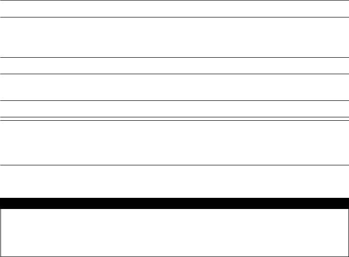
6.The WIBGET monitor will begin sending data. Once the download has been completed, exit the download menu. A table of data will now appear on the screen (similar to the one shown in Table 1 below).
7.Use the other menu functions to analyze, save and print the data.
RSS-214 WIBGET DATA |
|
|
|
|
File: :\WBGT\DATA\SAMPLE.WBG |
|
|||
|
|
|
|
|
|
|
|
|
|
Upload Date: 2006/09/17 |
|
|
|
|
Time: 13.46 |
|
|
Desc: Sample |
|
|
|
|
|
|
|
|
|
|
|
Record Number |
|
Time |
Wet Bulb |
Dry |
Globe |
WBGT |
|
Metabolic - TWM |
|
|
|
(hh:mm) |
|
Bulb |
|
In |
Out |
|
TWM RATE |
|
|
|
|
|
|
|
|
|
|
Test: 2006/09/17 |
|
Location: Floor |
|
CLO Value: 1.0 |
|
TWM: IN - 1 hour |
|
||
|
|
|
|
|
|
|
|
|
|
2 |
|
11:12 |
16.7 |
21.6 |
38.0 |
23.1 |
21.4 |
|
0.0 |
|
|
|
|
|
|
|
|
|
|
3 |
|
11:17 |
19.4 |
27.4 |
49.8 |
28.5 |
26.3 |
|
0.0 |
|
|
|
|
|
|
|
|
|
|
4 |
|
11:22 |
19.6 |
27.7 |
51.9 |
29.3 |
26.9 |
|
0.0 |
|
|
|
|
|
|
|
|
|
|
5 |
|
11:27 |
19.9 |
27.8 |
52.3 |
29.6 |
27.2 |
|
0.0 |
|
|
|
|
|
|
|
|
|
|
6 |
|
11:32 |
19.6 |
27.3 |
51.4 |
29.1 |
26.7 |
|
0.0 |
|
|
|
|
|
|
|
|
|
|
7 |
|
11:37 |
19.6 |
27.6 |
51.4 |
29.2 |
26.8 |
|
0.0 |
|
|
|
|
|
|
|
|
|
|
8 |
|
11:42 |
19.6 |
27.5 |
51.3 |
29.1 |
26.8 |
|
28.5 |
|
|
|
|
|
|
|
|
|
|
9 |
|
11:47 |
19.6 |
27.5 |
50.8 |
28.9 |
26.6 |
|
29.0 |
|
|
|
|
|
|
|
|
|
|
10 |
|
11:52 |
19.5 |
27.3 |
50.9 |
28.9 |
26.5 |
|
29.0 |
|
|
|
|
|
|
|
|
|
|
11 |
|
11:57 |
19.4 |
27.2 |
50.6 |
28.8 |
26.4 |
|
29.0 |
|
|
|
|
|
|
|
|
|
|
12 |
|
12:02 |
19.3 |
27.1 |
50.5 |
28.7 |
26.3 |
|
28.9 |
|
|
|
|
|
|
|
|
|
|
13 |
|
12.07 |
19.5 |
27.2 |
51.2 |
29.0 |
26.6 |
|
28.9 |
|
|
|
|
|
|
|
|
|
|
14 |
|
12:12 |
19.5 |
27.4 |
51.2 |
29.0 |
26.6 |
|
28.9 |
|
|
|
|
|
|
|
|
|
|
15 |
|
12:17 |
19.3 |
27.3 |
51.2 |
20.9 |
26.5 |
|
28.8 |
|
|
|
|
|
|
|
|
|
|
16 |
|
12:22 |
19.5 |
27.3 |
50.8 |
20.9 |
26.5 |
|
28.9 |
|
|
|
|
|
|
|
|
|
|
17 |
|
12.27 |
19.5 |
27.3 |
51.0 |
28.9 |
26.6 |
|
28.9 |
|
|
|
|
|
|
|
|
|
|
18 |
|
12:32 |
19.4 |
27.6 |
51.2 |
28:9 |
26.6 |
|
28.9 |
|
|
|
|
|
|
|
|
|
|
19 |
|
12:37 |
19.4 |
27.4 |
50.7 |
28.8 |
26.4 |
|
28.9 |
|
|
|
|
|
|
|
|
|
|
20 |
|
12:42 |
19:6 |
27.7 |
51.3 |
29.1 |
26.7 |
|
28.9 |
|
|
|
|
|
|
|
|
|
|
21 |
|
12:47 |
19.4 |
97.4 |
51.1 |
28.9 |
26.5 |
|
28.9 |
|
|
|
|
|
|
|
|
|
|
22 |
|
12:52 |
19.5 |
27.4 |
51.2 |
29.0 |
26.6 |
|
29.0 |
|
|
|
|
|
|
|
|
|
|
23 |
|
12:57 |
19.5 |
27.5 |
50.9 |
29.9 |
26.5 |
|
29.0 |
|
|
|
|
|
|
|
|
|
|
24 |
|
13:02 |
19.6 |
27.6 |
51.2 |
29.0 |
26.7 |
|
29.0 |
|
|
|
|
|
|
|
|
|
|
25 |
|
13:07 |
19.6 |
27.8 |
51.5 |
29.2 |
26.8 |
|
29.0 |
|
|
|
|
|
|
|
|
|
|
26 |
|
13:12 |
19.6 |
28.0 |
51.3 |
29.1 |
26.8 |
|
0.0 |
|
|
|
|
|
|
|
|
|
|
27 |
|
13:17 |
19.5 |
27.8 |
51.5 |
29.1 |
26.7 |
|
0.0 |
|
|
|
|
|
|
|
|
|
|
28 |
|
13:22 |
10.7 |
27.9 |
51.7 |
29.3 |
26.9 |
|
0.0 |
|
|
|
|
|
|
|
|
|
|
29 |
|
13:27 |
19.4 |
27.3 |
51.4 |
29.0 |
26.6 |
|
0.0 |
|
|
|
|
|
|
|
|
|
|
30 |
|
13:32 |
19.3 |
27.3 |
51.2 |
28.9 |
26.5 |
|
0.0 |
|
|
|
|
|
|
|
|
|
|
31 |
|
13:37 |
19.4 |
27.5 |
51.4 |
29.0 |
26.6 |
|
0.0 |
|
|
|
|
|
|
|
|
|
|
Table 1 (Typical Printer/Screen Output)
10
MAINTENANCE
 WARNING
Never alter or modify this instrument. Substitution of components may impair intrinsic safety. Doing so may adversely affect product performance and result in sickness or death. Repair or replace parts only with the 3M components approved for this unit. Failure to do so may adversely affect product performance and result in sickness or death.
Wet Bulb
Operation of the Wet Bulb with a fouled wick (e.g. discolored, stiff or will not wet) may lead to errant (high) readings.
Wick Replacement
To replace a fouled wick, pull it and its sponge straight upward over the sensor. Slide a new proper fitting 3M wick over the sensor such that it is snug over the tip and reaches the bottom of the reservoir. To prevent water spillage, a snug fitting 3M sponge should be placed over the wick encased sensor and positioned in the mouth of the reservoir. Dampening the sponge and wick facilitates removal and replacement.
Water Treatment
For maximum accuracy and extended wick life, distilled water should be used (available from most pharmacies). Alternately, demineralized tap water may be used. Be sure to follow instructions supplied with the demineralizer carefully.
Cleaning
CAUTION
Avoid the use of harsh cleaning materials, abrasives and other organic solvents. Such materials may permanently scratch the surfaces and damage the display window, labels, or monitor housing.
To clean external surfaces, use a soft wipe/tissue dampened with a mild detergent in warm water solution.
Storage
Remove each sensor by pulling straight up (DO NOT TWIST) on its connector collar. Empty the Wet Bulb reservoir and squeeze excess water from its sponge. Return all items to their proper location in the carrying case.
BATTERY
 WARNING
Battery must be replaced in a non-hazardous area only. Battery replacement is not an intrinsically safe operation. Use only approved battery. Failure to do so may result in sickness or death.
Only charge the instrument in non-hazardous areas using a 3M battery charger (AC adapter). Battery charging and operating with AC adapter is not an intrinsically safe operation. Do not attempt to charge alkaline batteries. Doing so may adversely affect product performance and result in sickness or death.
CAUTION
Observe proper polarity when inserting the battery. Polarity is marked on the inside of the battery compartment.
This instrument may contain a nickel metal hydride (NiMH) battery. Dispose of battery in accordance with local regulations.
The WIBGET monitor is powered by a rechargeable 9v (8.4v) Ni-MH battery and comes with an external charger. In addition the WIBGET monitor can operate on a nonrechargeable 9v alkaline battery or the charger (AC adapter).
Charging
When the battery nears full discharge, “LOBAT” appears in the upper right-hand corner of the display. For continued/continuous operation or to simply recharge the battery, connect the charger via its receptacle (12vdc) located on the lower left side of the monitor. Recharging requires a minimum of 12 hours. Although Ni-MH batteries may be recharged many times, they eventually degrade, requiring replacement.
Replacement
With the power ‘OFF’, remove all four screws from the rear case and open the instrument. Noting the battery’s location, replace it. Reinstall the rear case using the reverse process.
CALIBRATION
The WIBGET monitor base unit and all three sensors can be returned to 3M for calibration to NIST standards. A CERTIFICATE OF INSTRUMENT CALIBRATION will be issued only if the WIBGET base unit along with all three of its sensors have passed calibration. Traceable certification and before/after data can also be provided at an additional cost. It is recommended that the WIBGET monitor be calibrated yearly.
11

TROUBLESHOOTING
Use the following table to help identify possible causes and corrective actions for problems you may experience. If you need further assistance, contact your 3M Service Center or call 3M Technical Service in U.S.A., 1-800-243-4630. In Canada, call Technical Service at 1-800-267-4414.
Problem |
Possible Cause |
Possible Solution |
|
|
|
Unit doesn’t respond when switched on |
Battery/charger failing. |
Replace battery |
|
|
|
Battery doesn’t last long enough |
Battery/charger failing. |
Replace battery |
|
|
|
Very high reading(s). |
Connector wet. |
Rinse connector with iso-propyl alcohol and dry. |
|
|
|
WIBGET monitor sends data but PC does not receive. |
RSS-214 internal switch #4 setting incorrect. |
Reset switch #4 then reboot PC to reset com port. |
|
|
|
Computer produces nonsense. |
RSS-214 internal switch #1 setting incorrect. |
Set to alternate position (switch baud rates are 300 or 1200). |
|
|
|
Computer locks up |
RSS-214 internal switch #3 setting incorrect. |
Set to alternate position. |
|
|
|
If an ‘E’Code appears on the display (even momentarily) during POWER ON/SELF DIAGNOSTICS, refer to the following:
Code Displayed |
Possible Cause |
Possible Solution |
|
|
|
E1, E2, E3 |
Component failure |
Return for repair |
|
|
|
E4, E5 |
Analog O/P out of calibration |
Adjust Trim R to 250 mv at 25.0°C. |
|
|
|
E6GT, E6WB, E6DB |
Sensor specific malfunction |
Plug in, clean or replace affected sensor(s) |
|
|
|
E7, E8 |
Memory failure or low battery |
Return for repair, or recharge/replace battery |
|
|
|
PRODUCTS, ACCESSORIES AND PARTS
 WARNING
Never alter or modify this instrument. Substitution of components may impair intrinsic safety. Doing so may adversely affect product performance and result in sickness or death. Repair or replace parts only with the 3M components approved for this unit. Failure to do so may adversely affect product performance and result in sickness or death.
WIBGET Heat Stress Monitors
Part # |
Description |
RSS-214 |
3M™ WIBGET™ Heat Stress Monitor |
RSS-214DL |
3M™ WIBGET™ Heat Stress Monitor with Data Logging |
Replacement Parts and Accessories |
|
|
|
Part # |
Description |
323-1402 |
3M™ Dry Bulb Sensor |
323-1203 |
3M™ Wet Bulb Sensor |
323-5020 |
3M™ Wet Bulb Kit (contains demineralizer, 6 wicks & 2 sponges) |
323-1003 |
3M™ Globe Sensor |
323-5025 |
3M™ 9 Volt NiMH Battery and Charger |
227-0500 |
3M™ 9 Volt NiMH Battery |
229-0102 |
3M™ Water bottle |
323-2220 |
3M™ Personal Sensor Set (with hardhat clip attachment) |
323-2200 |
3M™ 10 ft Sensor Assembly Cable |
323-2201 |
3M™ 20 ft Sensor Assembly Cable |
323-2202 |
3M™ 50 ft Sensor Assembly Cable |
323-2203 |
3M™ 100 ft Remote Sensor Assembly Cable |
323-2202wp |
3M™ 50 ft Weatherproof Remote Sensor Assembly Cable |
323-2203wp |
3M™ 100 ft Weatherproof Remote Sensor Assembly Cable |
12
IMPORTANT NOTICE
WARRANTY
3M warrants its Heat Stress Monitors RSS-214 and RSS-214DL, to be free from defects in material and workmanship in normal service and under normal conditions for 1 year from date of manufacture.
This warranty is void if the 3M Heat Stress Monitor has been damaged by accident, misuse, neglect, improper service, or other causes not arising out of defects in material or workmanship. This warranty does not include replaceable items, such as wicks, sponges, demineralizer, and batteries, which are considered part of a regular maintenance program. Any implied warranties arising out of the sale of 3M’s Heat Stress Monitors including but not limited to the implied warranties of merchantability and fitness for a particular purpose, are limited in duration to the periods stated above. 3M shall not be liable for loss of use of any of its products or incidental or consequential costs, expenses, or damages incurred by the purchaser or any other user.
REMEDY
Should the 3M Heat Stress Monitor fail in normal service under normal conditions through no fault of the purchaser or any other user during the warranty period, return the detector or monitor to a 3M authorized warranty repair service center. For the location of 3M authorized repair service centers, call 3M in U.S.A. at, 1-800-243-4630. In Canada, call Technical Service at 1-800-267-4414. No charges will be made for repair or replacement. Each repaired unit is warranted for sixty (60) days or the remaining portion of the original equipment’s warranty, whichever is longer.
EXCLUSIONS TO WARRANTY: THE FOREGOING WARRANTY IS EXCLUSIVE AND IS IN LIEU OF ALL OTHER WARRANTIES EXPRESS, IMPLIED, OR STATUTORY, INCLUDING WARRANTY OF MERCHANTABILITY, FITNESS FOR A PARTICULAR PURPOSE OR OTHER WARRANTY OF QUALITY.
LIMITATION OF LIABILITY: THE FOREGOING CONSTITUTES THE SOLE AND EXCLUSIVE REMEDY AND IS LIEU OF ANY AND ALL OTHER REMEDIES WHICH MAY BE AVAILABLE. This warranty becomes void immediately should any repair of or alterations to the warranted equipment be made without authorization by 3M.
FOR MORE INFORMATION
In United States, contact: Internet: www.3M.com/OccSafety
Technical Assistance: 1-800-243-4630
For other 3M products:
1-800-3M-HELPS or 1-651-737-6501
In Canada, contact :
Internet : www.3M.com/CA/OccSafety Technical Assistance : 1-800-267-4414
For other 3M products :
1-800-364-3577
13
3
Moniteur de stress thermique RSS-214 WIBGET™
Directives d’utilisation
(Conserver ces directives à titre de référence)
FUNCTION
VIEW
time base
|
OUT WBGT |
MONITOR / log |
°F |
|
|
start |
|
SELECT
°C/°F
14

TABLE DES MATIÈRES
Renseignements généraux |
|
sur la sécurité |
16 |
Usage prévu |
16 |
Liste des mises en garde |
|
et des avertissements |
16 |
DIRECTIVES ET LIMITES D’UTILISATION |
17 |
Description générale |
17 |
SPÉCIFICATIONS |
18 |
WIBGT |
19 |
INSTALLATION |
19 |
Installation des capteurs |
19 |
Préparation du réservoir humide |
19 |
Emplacement et environnement |
19 |
Directives d’utilisation |
20 |
Mise sous tension/hors tension |
20 |
Autodiagnostics |
20 |
Mode de surveillance |
20 |
Sortie analogique/d’enregistreur |
|
(mode de surveillance seulement) |
20 |
ENREGISTREMENT DES DONNÉES (optionnel) |
21 |
Configuration et affichage du |
|
calendrier/de l’horloge |
21 |
Mode d’enregistrement |
21 |
Enregistrement à la demande |
22 |
Affichage en cours d’enregistrement |
22 |
Arrêt d’enregistrement des données |
22 |
Arrêt du mode d’enregistrement des |
|
données et retour au mode de surveillance |
22 |
TÉLÉCHARGEMENT DES DONNÉES |
22 |
Configuration nécessaire |
22 |
Installation du logiciel du moniteur |
|
de stress thermique WIBGET |
22 |
Téléchargement des données |
22 |
ENTRETIEN |
24 |
Réservoir humide |
24 |
Remplacement des mèches |
24 |
Traitement de l’eau |
24 |
Nettoyage |
24 |
Entreposage |
24 |
PILE |
24 |
Chargement |
24 |
Remplacement |
24 |
ÉTALONNAGE |
24 |
DÉPANNAGE |
25 |
PRODUITS, ACCESSOIRES ET PIÈCES |
25 |
GARANTIE |
26 |
RENSEIGNEMENTS SUPPLÉMENTAIRES |
26 |
FRANÇAIS
15

RENSEIGNEMENTS GÉNÉRAUX SUR LA SÉCURITÉ
Usage prévu
Le moniteur de stress thermique RSS-214 WIBGET™ de 3M™ est conçu pour mesurer les facteurs environnementaux qui peuvent contribuer au stress thermique.
Liste des mises en garde et des avertissements énoncés dans les présentes Directives d’utilisation
 MISE EN GARDE
Ce moniteur aide à mesurer certains facteurs environnementaux qui peuvent contribuer au stress thermique. Une mauvaise utilisation peut provoquer des problèmes de santé ou la mort. Pour tout renseignement sur l‘utilisation adéquate de ce produit, consulter son superviseur, lire les Directives d‘utilisation ou communiquer, au Canada, avec le Service technique au 1 800 267 4414.
Chaque utilisateur de ce matériel doit lire et comprendre les présentes Directives d‘utilisation. L‘utilisation de ce matériel par des personnes qui n’ont pas reçu la formation nécessaire ou qui n’ont pas les qualifications requises, ou l’utilisation non conforme aux présentes Directives d’utilisation, peut nuire au bon fonctionnement du produit et provoquer des problèmes de santé ou la mort.
N’utiliser ces capteurs et cet instrument que pour la surveillance des facteurs environnementaux pour lesquels ils sont conçus. Tout manquement à ces directives peut nuire au bon fonctionnement du produit et provoquer des problèmes de santé ou la mort. Pour tout renseignement sur l‘utilisation adéquate de ce produit, consulter son superviseur, lire les Directives d‘utilisation ou communiquer, au Canada, avec le Service technique au 1 800 267 4414.
Chaque fois que l’appareil est mis sous tension, ce dernier effectue un auto-test. En cas d’échec de l’auto-test ou d’affichage d’un code d’erreur, ne pas utiliser cet appareil. Cela risque de nuire au bon fonctionnement du produit et provoquer des problèmes de santé ou la mort.
Le port de sortie de données en série RSS-214DL RS 232 ne doit être utilisé que dans un endroit non dangereux. L’utilisation du port de sortie des données n’est pas une opération intrinsèquement sécuritaire. Tout manquement à ces directives peut provoquer des problèmes de santé ou la mort.
Ne jamais modifier cet instrument. La substitution de composants risque de compromettre la sécurité intrinsèque. Cela risque de nuire au bon fonctionnement du produit et provoquer des problèmes de santé ou la mort.
Ne réparer l’instrument et n’en remplacer les composants qu‘avec des composants 3M approuvés pour l‘appareil. Tout manquement à ces directives peut nuire au bon fonctionnement du produit et provoquer des problèmes de santé ou la mort.
Ne remplacer la pile que dans un endroit non dangereux. Le remplacement de la pile n’est pas une opération intrinsèquement sécuritaire. N’utiliser que des piles approuvées. Tout manquement à ces directives peut provoquer des problèmes de santé ou la mort.
Ne recharger l’instrument que dans des zones sans danger à l’aide d’un bloc d’alimentation 3M (adaptateur c.a.). Le chargement et le fonctionnement de piles au moyen d’un adaptateur c.a. ne sont pas des opérations intrinsèquement sécuritaires. Ne pas tenter de recharger des piles alcalines. Cela risque de nuire au bon fonctionnement du produit et provoquer des problèmes de santé ou la mort.
AVERTISSEMENT
Ne pas tordre les capteurs une fois que ceux-ci sont insérés dans l’unité principale. Cela risque d’endommager le capteur ou son connecteur. Pour aider à maintenir l’exactitude du capteur, la mèche du réservoir humide doit rester humide pendant le fonctionnement de l’instrument.
Conserver tous les connecteurs propres et secs. Si un connecteur devient humide, il doit être séché à fond avant l’utilisation de l’instrument. L’état des compartiments des capteurs peut être vérifié en retirant tous les capteurs, en mettant l’appareil sous tension, puis en examinant si toutes les fonctions indiquent 0,0 ± 0,3 °C or 32,0 ± 0,5 °F. Si les lectures sont différentes, alors ne pas utiliser l’instrument jusqu’à ce que la cause soit déterminée et corrigée.
Ne pas exposer le réservoir sec à des températures supérieures à 65 °C (150 °F). Cela risque d’endommager l’unité principale. Pour surveiller les environnements dont la température est supérieure à 65 °C (150 °F), utiliser un accessoire doté d’un capteur à distance et déplacer l’unité principale dans un endroit plus frais.
Éviter d’utiliser des agents de nettoyage forts, des abrasifs et d’autres solvants organiques. De tels produits peuvent égratigner les surfaces de façon permanente et endommager la fenêtre d’affichage, les étiquettes ou le boîtier du moniteur.
Insérer la pile selon la polarité appropriée. La polarité est indiquée à l’intérieur du compartiment de la pile.
Cet instrument peut contenir une pile à hydrure métallique de nickel (NiMh). Mettre la pile au rebut conformément aux règlements locaux.
16

DIRECTIVES ET LIMITES D‘UTILISATION
Important
Avant d‘utiliser cet instrument, chaque utilisateur doit lire et comprendre les présentes Directives d‘utilisation. Conserver ces Directives d‘utilisation à titre de référence.
Description générale
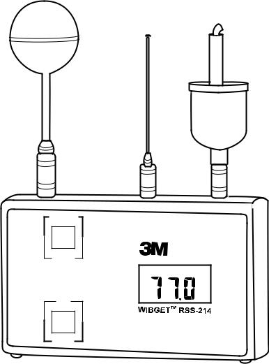
Les présentes Directives d’utilisation s’appliquent au moniteur de stress thermique RSS-214 WIBGET de 3M™. Cet instrument est un thermomètre globe mouillé portatif doté d’un microprocesseur, conçu pour mesurer certains facteurs environnementaux qui peuvent contribuer au stress thermique. Un microprocesseur interne commande les indications et les réponses aux signaux reçus par les capteurs fixés sur le dessus de l’appareil. Lorsqu’il est sous tension, il surveille de façon continue l’air ambiant.
Le moniteur WIBGET est alimenté par une pile rechargeable à hydrure métallique de nickel (NiMh) de 9 volts ou une pile alcaline non rechargeable de 9 volts. Il est conçu pour être intrinsèquement sécuritaire lorsqu’il est alimenté par des piles. Le moniteur WIBGET est homologué intrinsèquement sécuritaire par la CSA pour les endroits dangereux de classe 1, division I, groupes A, B, C et D.
Les composants du moniteur WIBGET sont montés dans un boîtier en plastique de 12,2 x 6,9 x 3,6 cm - haut./larg./prof. (3,75 x 6,2 x 1,75 po - haut./larg./prof.) (Fig. 1). L’écran (ACL) et les touches de fonctions (FUNCTION) et de sélections (SELECT) se trouvent sur la face avant de l’appareil. L’interrupteur On/Off, la sortie des données analogiques et la prise du chargeur se trouvent sur le côté gauche de l’appareil. Sur le dessus de l’appareil se trouvent les broches de connecteur des capteurs du globe, du réservoir sec et du réservoir humide. Une étiquette sur laquelle figurent l’information en matière de sécurité intrinsèque et le numéro de série se trouve à l’arrière de l’appareil.
Capteur du globe |
|
Capteur du réservoir sec |
|
Capteur du réservoir humide |
|
|
|
|
|
|
|
|
|
|
|
|
|
ON
OFF
Analog Output 0-1V
Charger 12vdc
Touche des fonctions (Function) |
FUNCTION |
|
|
VIEW |
|
|
time base |
|
|
OUT |
WBGT |
|
MONITOR / log |
°F |
|
|
|
|
start |
|
|
SELECT |
|
Touche de sélection (Select) |
°C/°F |
Affichage ACL |
Fig. 1
17
 Loading...