


3MTM Water Filtration Products
Installation and Operating Instructions for SCALEGARDTM LP REVERSE OSMOSIS FILTRATION SYSTEM
SGLP-RO
Installer: Please leave this manual with owner/operator.

LIMITED WARRANTY
3M Purification Inc. warrants SGLP-RO only to be free from defects in material and workmanship for two (2) years from the date of purchase. The disposable filter cartridge is warranted from defects in material and workmanship for a period of one (1) year from the date of purchase. This warranty does not cover failures resulting from abuse, misuse, alterations or damage not caused by 3M Purification Inc. or failure to follow installation and use instructions. No warranty is given as to the service life of any filter cartridge or membrane as it will vary with local water conditions and consumption. 3M PURIFICATION INC. MAKES NO OTHER WARRANTIES OR CONDITIONS, EXPRESS OR IMPLIED, INCLUDING, BUT NOT LIMITED TO, ANY IMPLIED WARRANTY OR CONDITION OF MERCHANTABILITY OR FITNESS FOR A PARTICULAR PURPOSE OR ANY IMPLIED WARRANTY OR CONDITION ARISING OUT OF A COURSE OF DEALING, CUSTOMER OR USAGE OF TRADE. If the Product fails to satisfy this Limited Warranty during the warranty period, 3M Purification Inc., at it’s option, will replace the Product or refund your Product purchase price. This warranty does not cover labor. The remedy stated in this paragraph is Customer’s sole remedy and 3M Purification Inc.’s exclusive obligation.
This warranty gives you specific legal rights, and you may have other rights which may vary from state to state, or country to country. For any warranty questions, please call 866.990.9785 or mail your request to: Warranty Claims, 3M Purification Inc., 400 Research Parkway, Meriden, CT 06450. Proof of purchase (original sales receipt) must accompany the warranty claim, along with a complete description of the Product, model number and alleged defect.
Limitation of Liability: 3M Purification Inc. will not be liable for any loss or damage arising from this 3M Purification Inc. product, whether direct, indirect, special, incidental, or consequential, regardless of the legal theory asserted, including warranty, contract, negligence or strict liability. Some states and countries do not allow the exclusion or limitation of incidental or consequential damages, so the above limitation or exclusion may not apply to you.

IMPORTANT INSTALLATION INSTRUCTIONS
Always follow these safety precautions when installing and operating the water filter system:
DO NOT use with water that is microbiologically unsafe or of unknown quality without adequate disinfection before or after the system.
DO NOT use a torch or other high temperature sources near filter or cartridge. DO NOT install on line pressures above 125 psi (862 kPa).
DO NOT install on hot water line. Maximum temperature allowed is 100°F (38°C). DO NOT install in direct sunlight.
DO NOT reverse connections. The system must be installed with the inlet and outlet as labeled.
DO NOT install filter system in locations where it can be damaged by other freestanding equipment. DRAIN filter system at temperatures below 40°F (4.4°C). Protect from freezing.
INSTALLATION must comply with existing state or local plumbing codes.
This piece of equipment is made in America and has American sizes on hardware. All metric conversions are approximate and vary in size.
FEEDWATER PARAMETERS
Be sure to confirm that the feedwater falls within the limits shown below. If you’re not sure if this has been done, check with your distributor before installing the system. This is important because failures caused by water related problems are not covered under the system warranty.
Feed TDS . . . . . . . . .Up to 2,000 ppm (mg/L)
Hardness* . . . . . . . . . . .<10 grains (171 mg/L)
Iron (Fe) . . . . . . . . . . . . . . . . . . . . . .<0.1 mg/L
Hydrogen Sulfide . . . . . . . . . . .none allowable
Feed pH . . . . . . . . . . . . . . . . . . . . . . . . . .4-11
Free chlorine . . . . . . . . . . . . . . . . . . . .<2 mg/L
Manganese (Mn) . . . . . . . . . . . . . .<0.05 mg/L
Turbidity . . . . . . . . . . . . . . . . . . . . . . . .<5 NTU
* NOTE: For waters over 10 grain hard, a 3M water softener is recommended for pretreatment. Consult 3M technical services for correct sizing.
PARTS LIST
THE FOLLOWING PARTS ARE INCLUDED WITH THE SCALEGARD REVERSE OSMOSIS WATER FILTRATION SYSTEM. PLEASE UNPACK THE CONTENTS FROM THE PRODUCT BOX AND CHECK TO VERIFY THAT ALL OF THE PARTS LISTED BELOW ARE INCLUDED. SHOULD ANY PARTS BE MISSING, PLEASE CONTACT 3M PURIFICATION INC. AT 866.990.9785
QTY DESCRIPTION
1 TANK & BRACKET ASSEMBLY
1 PREFILTER CARTRIDGE
1 REVERSE OSMOSIS MEMBRANE CARTRIDGE
1 WATER SAMPLE VALVE ASSEMBLY (SEE FIGURE 1)
1 1’ LENGTH OF 3/8” BLUE TUBING
1 10’ LENGTH OF RED TUBING
1 ADAPTER - STEM X BARB (1/4X1/4”)
1 ADAPTER - STEM X BARB (3/8 X 1/4”)
MOUNTING
1)Remove the mounting bracket template from this manual. Tape it to the wall where the mounting bracket is to be installed.
2)Install mounting screws (not included) into each of the keyhole locations on the template. Be sure to leave a 1/8” to 1/4” space between the bottom of the screw head and the wall so that the bracket can be hung. NOTE: Mounting hardware must be capable of supporting a minimum of 50 lbs (22.7 kg).
3)Hang the Bracket/Tank Assembly from the mounting screws.
4)Once the bracket is hung, tighten the mounting screws so that the bracket is snug between the screw and the wall. Note: Make sure that the bracket is securely mounted to a wall stud or other appropriate wall structure.
PLUMBING CONNECTIONS
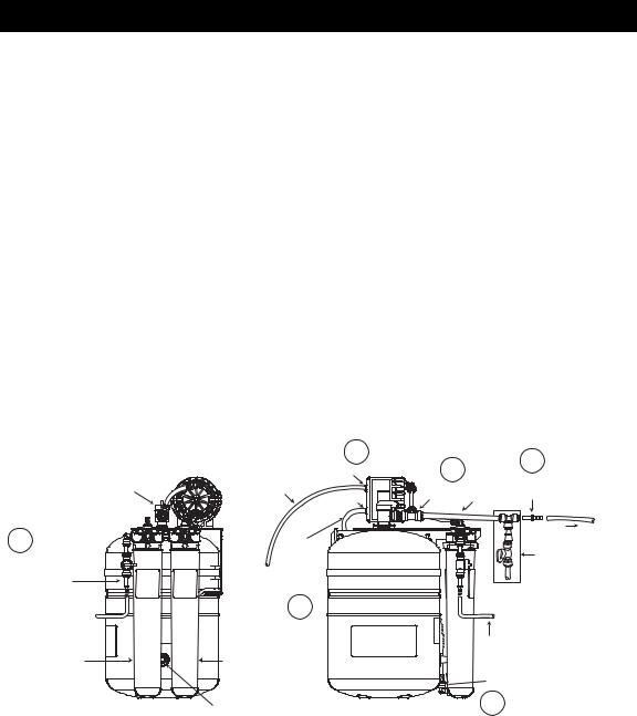
Note: The ScaleGard LP Reverse Osmosis Water Filtration System requires a minimum 50 psi inlet water pressure. If inlet water pressure is less than 50 psi, a water booster pump may be required. Refer to Figure 1 for proper tubing connections.
All connections are made with “Push-In” connectors. Refer to Figure 2 on the use of “Push-In” plastic fittings. Use care in routing the tubing to ensure that there are no bends or kinks.
1)Shut off water supply and water booster pump (if applicable).
2)Insert the 1/4” x 1/4” Stem X Barb Adapter (See Figure 1) into Inlet Water Valve. Run a 1/4” I.D. hose from the Water Supply or Booster Pump to the Inlet Water Valve.
3)Insert one end of the 3/8” blue tubing (included) into one end of the outlet tee on the RO system and the other end to one side of the Water Sample Valve Assembly. See Figure 1.
4)Insert the 3/8” x 1/4” Stem x Barb adapter into the open 3/8” port of the sample valve assembly. Run a 1/4” I.D. hose from the water sample valve assembly to the inlet of the Foodservice Equipment. See Figure 1.
5)Remove the white plug from the bottom port of the RO Module.
6)Remove the red cap from the RO module and moisten the o-rings with water. Insert the cartridge into the filter head. Be sure the ears on the cartridge line up with the spaces in the head. Then turn the cartridge 1/4 turn to the right.
7)Connect the 1/4” red tube from the “Brine In” side of the permeate pump to bottom port of the RO Module. (See Figure 3).
8)Run the separate 1/4” red tubing (included) from the “Brine Out” port of the permeate pump to the drain.
Tank Shut-Off Valve
Step
2
Inlet Water Valve 
1/4” x 1/4”
Stem x Barb Adapter
Feedwater from Incoming 
 Water Line or Booster Pump
Prefilter Cartridge
P/N: 55706-10
Side View
|
Step |
|
|
|
8 |
|
Step |
|
“Brine Out” |
Step |
4 |
1/4” Red Tubing |
Port |
3 |
3/8” x 1/4” |
(To Drain) |
|
3/8” |
|
|
“Brine In” |
Outlet Tee Blue Tubing |
Stem x Barb Adapter |
|
Port |
|
|
|
To Equipment |
|
Red |
|
|
Tubing |
Water Sample |
|
(To Bottom |
Valve Assembly |
|
of RO |
||
|
||
Membrane |
|
|
Cartridge) |
|
Step
7
|
Feedwater from Incoming |
|
Reverse Osmosis (RO) |
Water Line or |
|
Booster Pump |
||
Membrane |
||
|
||
P/N: 55987-20 |
R O M e m b r a n e P l u g |
|
|
||
|
Step |
|
Schrader Air Valve |
5 |
|
|
Front View
Figure 1
 Loading...