


W-2808

3
Carbon Monoxide Monitor and
Retrofit Carbon Monoxide Monitor
Kit W -2808/37027
User Instructions
(Keep these instructions for reference)


i
English
TABLE OF CONTENTS
GENERAL SAFETY INFORMATION 2
– Intended Use 2
– List of Warnings and Cautions within these User Instructions 2
USE INSTRUCTIONS AND LIMITATIONS 3
– Use For 3
– Do Not Use For 3
– General Description 3
SPECIFICATIONS 6
PRODUCTS,ACCESSORIES AND P AR TS 7
– 3MTMCarbon Monoxide Monitor 7
– 3MTMRetrofit Carbon Monoxide Monitor Kit W-2808/37027 7
– 3MTMAccessories and Parts 7
ASSEMBLY 8
SET UP PROCEDURES AND PERFORMANCE CHECK 10
– Monitor Calibration Frequency 10
OPERATING INSTRUCTIONS 11
– Normal Operation 11
– Calibration 12
REPLACEMENT PART INSTRUCTIONS 13
– Batteries 13
– 3M
TM
Carbon Monoxide Sensor 529-05-22 13
TROUBLESHOO TING 15
IMPORTANT NOTICE 17
– W arranty 17
– Remedy 17
FOR MORE INFORMATION 18

2
GENERAL SAFETY INFORMATION
Intended Use
The 3MTMCarbon Monoxide (CO) Monitor and the 3MTMRetrofit Carbon Monoxide (CO)
Monitor Kit are designed to provide continuous, direct read CO monitoring for compressed
air used with supplied air respirators.
List of Warnings and Cautions within these User Instructions
• These products are designed for carbon monoxide monitoring. Misuse may result in
sickness or death. For proper use, see supervisor or User Instructions, or call 3M in U.S.A.,
1-800-243-4630. In Canada, call Technical Service at 1-800-267-4414.
• The impedance of any connected load device at the REM ALARM (remote alarm) jack must
be greater or equal to 12 ohms, when operating from internal batteries or AC adapter. Failure
to do so may damage the carbon monoxide monitor and result in sickness or death.
• The intrinsic safety of the carbon monoxide monitor is voided when remote alarm is used.
• The intrinsic safety of the carbon monoxide monitor is voided when the 110-120 volt AC
adapter is used.
• Your employer must provide breathing air that meets at least the requirements of the
specification for Grade D breathing air, as described in the Compressed Gas Association
Commodity Specification G-7.1-1997 in the United States. In Canada refer to CSA standard
Z180.1, for the quality of the compressed breathing air. Failure to do so may result in
sickness or death.
• Use of equipment described in these User Instructions must be in accordance with applicable
health and safety standards, or pursuant to the recommendations of an industrial hygienist.
• Each person using this equipment must read and understand the information in these User
Instructions. Use of this equipment by untrained or unqualified persons, or use that is not
in accordance with these User Instructions, may adversely affect product performance and
result in sickness or death.
W WARNING
CAUTION:
• Observe proper polarity when inserting batteries. Polarity is marked on the inside of the drawers.
• The sensor in the carbon monoxide monitor contains a small amount of sulfuric acid. Always
wash hands thoroughly after handling sensor cell. Sulfuric acid is poisonous and can cause
severe burns. Do not allow acid to contact skin or eyes. If eyes are exposed to acid, flush
thoroughly and seek immediate medical attention.
3
English
USE INSTRUCTIONS AND LIMITATIONS
Important
Before use, each person using this equipment must read and understand these User Instructions.
Keep these instructions for reference.
Use For
Monitoring for carbon monoxide level in compressed air intended for respiratory protection systems.
Do Not Use For
Monitoring other compressed gas streams.
General Description
These User Instructions apply to the 3MTMCO Monitor mounted inside some of the 3MTMPortable
Compressed Air Filter and Regulator Panels and the 3M
TM
Retrofit CO Monitor Kit W-2808/37027.
The retrofit kit includes the 3M CO monitor and accessories to attach the CO monitor to a
3
/
8
-inch
port on a filter and regulator panel that does not currently have CO monitoring capability, such as
the 3M
TM
Compressed Air Filter and Regulator Panel W-2806/07006.
The 3M carbon monoxide monitor is designed to provide continuous, direct read CO monitoring
for compressed air used with supplied air respirators. An internal microprocessor controls the
indication and alarm functions in response to the signals of an electrochemical CO sensor. It
continuously monitors a compressed air sample introduced to its sensor at an approximate rate
of 1.0 standard cubic foot per hour (scfh) and gives an alarm when the CO in the sample reaches
a preset level (10 ppm in USA; 5 ppm in Canada).
The CO monitor is a battery powered unit utilizing two 9 volt alkaline batteries. It is designed to
be intrinsically safe when used on battery power. The CO monitor is CSA certified intrinsically
safe for Class I, Div. I, Groups A,B,C, and D Hazardous Locations when utilizing two 9 volt
alkaline batteries to power the monitor.
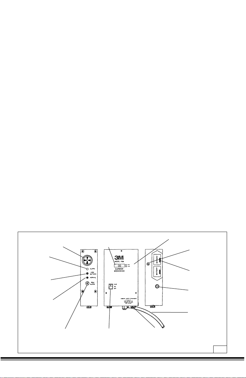
The components of the monitor are assembled into a black powder-coated aluminum housing
6˝ H x 4˝ W x 2˝ D overall. A hose barb, with plastic sample tube attached for introducing the
sample gas, extends from the bottom. Available at the front face are the OFF/ON/TEST switch,
the display (LCD), SPAN and ZERO adjustments.
The left side contains the indicating lights, the alarm buzzer, and the remote alarm jack.
Accessible on the right side are the two battery drawers and the auxiliary power jack. (Fig. 1)
Buzzer - Provides continuous tone
during high “CO” alarm; a pulsing tone
during certain malfunction conditions.
Display - LCD type refreshed
every 0.8 seconds; the red LED
light faintly blinks at same time.
Span & zero potentiometers
used in calibrating.
Screw sealed
access hole to
alarm level
potentiometer.
“Transistor”
type battery
holders
Auxiliary “power
source” jack
Air sample tube
Remove knurl thumbscrews for
access to “CO” sensor. Bottom pla te
sensor/sample tube assembly. Can be
moved approx. 2-3˝ before sensor wire
connections limit travel.
On/Off/Test switch-three
position type. Alternate
on-off position with
momentary “test”
position.
Remote alarm jack; for
plugging remote alarm
devices or relays to be
energized when monitor
goes into alarm.
Green normal LED
light; comes on steady
when monitor on &
goes off in alarm
conditions.
Yellow low battery
LED light; comes on
when 9 volt battery
voltage falls below
about 7.0 volts.
Red alarm, LED light;
blinks faintly during
normal operations
& on steady during
high “CO” alarm
conditions.
Fig. 1

4
The impedance of any connected load device at the REM ALARM (remote alarm) jack must be
greater or equal to 12 ohms, when operating from internal batteries or AC adapter. Failure to do
so may damage the carbon monoxide monitor and result in sickness or death.
W WARNING
Front Panel On/Off/Test Switch
This switch is a three-position type with alternate ON and OFF positions, and a momentary
TEST position. Switch is located at the lower left side.
Display
Display is a centrally located LCD type and is refreshed every 0.8 seconds; the red ALARM
light faintly blinks at the same time.
Span and Zero Adjustments
Located to the right of the display are two miniature multi-turn slotted-shaft potentiometers,
accessible through holes in the panel with a small screwdriver.
Left Side
The next five items are aligned toward the rear from the center of the left side panel and from
top to bottom are:
Buzzer
Buzzer is at the top of the side panel. It provides a continuous tone during high CO alarm,
a pulsing tone during certain malfunction conditions.
Alarm Light
Red ALARM light blinks faintly during normal operation and is on steadily during the high CO
alarm condition.
Low Battery Light
Yellow LOW BATTERY light comes on when battery voltage falls to where the instrument
will not function properly (about 7 volts DC). Batteries should be replaced at this time.
Normal Light
The green NORMAL light acts as a pilot light and glows when the instrument is turned on.
At the same time the red ALARM light flickers faintly at intervals of about one second.
Remote Alarm (REM ALARM)
A miniature size phone jack is provided for plugging in a remote alarm device so that the alarm
sound can be repeated at a distance from the instrument. The outer shell of the jack is grounded to
the case, and is negative. This jack will be energized at voltage about 8.5 volts DC when operating
from “fresh” internal batteries or about 8.9 volts DC when operating from AC adapter whenever
instrument is in alarm condition.
 Loading...