


3M NWS150, NWS200M, NWS150M, NWS200, NWS100M User Manual
...INSTALLATION AND OPERATING
INSTRUCTIONS
NWS RESIDENTIAL
WATER SOFTENERS
MODELS:
NWS100 NWS100M
NWS150 NWS150M
NWS200 NWS200M
Installer, please leave with homeowner.
Homeowner, retain for future reference.
INSTR2208 0110

SAFETY INFORMATION
Read, understand, and follow all safety information contained in these instructions prior to installation and use of the NWS Series Water Softener. Retain these instructions for future reference. Failure to follow installation, operation and maintenance instructions may result in property damage and will void warranty.
Intended use:
The NWS Series Water Softener is intended for use in softening water in homes and has not been evaluated for other uses. The system must be installed indoors near the point of entry of a home water line, and be installed by qualified professional installers according to these installation instructions.
EXPLANATION OF SIGNAL WORD CONSEQUENCES
WARNING |
Indicates a potentially hazardous situation, which, if not avoided, could result in death or serious injury and/or property damage. |
CAUTION |
Indicates a potentially hazardous situation, which, if not avoided, may result in minor or moderate injury and/or property damage. |
CAUTION |
Indicates a potentially hazardous situation, which, if not avoided, may result in property damage. |
|
 WARNING
To reduce the risk associated with choking:
• Do not allow children under 3 years of age to have access to small parts during the installation of this product.
To reduce the risk associated with ingestion of contaminants:
• Do not use with water that is microbiologically unsafe or of unknown quality without adequate disinfection before or after the system.
To reduce the risk of physical injury:
• Shut off inlet water supply and depressurize system as shown in manual prior to service.
To reduce the risk associated with a hazardous voltage:
•If the home electrical system requires use of the cold water system as an electrical safety ground, a jumper must be used to ensure a sufficient ground connection across the filter installation piping — refer installation to qualified personnel.
•Do not use the system if the power cord is damaged — contact qualified service personnel for repair.
To reduce the risk associated with back strain due to the heavy weight of the various system components:
• Follow safe lifting procedures.
 CAUTION
To reduce the risk associated skin, eye, and respiratory tract irritation from gravel and filter media during installation:
•Gravel and several types of filter media may be used in this product, depending upon the application. During installation, dust may cause irritation to skin, eyes, and respiratory tract.
•Utilize a NIOSH-approved dust filter mask, protective gloves, and appropriate eye protection when handling and pouring gravel and filter media.
•To request an MSDS relating to this product call 203-238-8965 or visit the web at http://solutions.3M.com/WPS/Portal/3M/EN_US/MSDS (click MSDS search). For emergencies, call 800-364-3577 or 651-737-6501 (24 hours).
CAUTION
To reduce the risk associated with property damage due to water leakage:
•Read and follow Use instructions before installation and use of this water treatment system.
•Installation and use MUST comply with existing state or local plumbing codes.
•Protect from freezing, relieve pressure and drain system when temperatures are expected to drop below 33°F (0.6°C).
•Do not install on hot water supply lines. The maximum operating water temperature of this filter system is 110°F (43.3°C).
•Do not install if water pressure exceeds 100 psi. If your water pressure exceeds 80 psi (552 kPa), you must install a pressure limiting valve. Contact a plumbing professional if you are uncertain how to check your water pressure.
•Do not install where water hammer conditions may occur. If water hammer conditions exist you must install a water hammer arrester. Contact a plumbing professional if you are uncertain how to check for this condition.
•Where a backflow prevention device is installed on a water system, a device for controlling pressure due to thermal expansion must be installed.
•Do not use a torch or other high temperature sources near filter system, cartridges, plastic fittings or plastic plumbing.
•On plastic fittings, never use pipe sealant or pipe dope. Use PTFE thread tape only, pipe dope properties may deteriorate plastic.
•Take care when using pliers or pipe wrenches to tighten plastic fittings, as damage may occur if over tightening occurs.
•Do not install in direct sunlight or outdoors.
•Mount system in such a position as to prevent it from being struck by other items used in the area of installation.
•Ensure all tubing and fittings are secure and free of leaks.
•SHUT OFF FUEL OR ELECTRIC POWER SUPPLY TO WATER HEATER after water is shut off.
•Do not install system where water lines could be subjected to vacuum conditions without appropriate measures for vacuum prevention.
•Do not apply heat to any fitting connected to bypass or control valve as damage may result to internal parts or connecting adapters.
•Install on a flat/level surface. It is also advisable to sweep the floor to eliminate objects that could pierce the brine tank.
To reduce the risk associated with property damage due to plugged water lines:
•Pay particular attention to correct orientation of control valve. Water flow should match arrow on control valve. The Inlet and Outlet of other water treatment equipment products will vary depending on the control valve brand used.
IMPORTANT NOTES
• Failure to follow instructions will void warranty.

TABLE OF CONTENTS
SECTION DESCRIPTION
1BEFORE INSTALLATION
2INSTALLATION
3REGENERATION INSTRUCTIONS (Timing Setting Instructions)
4SERVICE INSTRUCTIONS
5SPECIFICATION AND OPERATING DATA
6PARTS
7MAINTENANCE
8LIMITED WARRANTY
•Professional Installation Required: Installation requires shutting water off to home, cutting home water supply pipe and using a welding torch to add piping and fittings. Specialized tools and skills are required. Not a do-it-yourself type of project. Professional installation required!
IMPORTANT: SECTION 1: BEFORE INSTALLATION
Congratulations! We believe your purchase of this water softener will prove to be a very wise choice. When properly installed, operated, and maintained, your new softener will provide years of dependable service. Before starting the installation please read this manual all the way through for an overview, and then follow the installation in proper sequence. Failure to follow instructions will void warranty.
Inspecting And Handling Your Softener:
Inspect the equipment for shipping damage. If damaged, notify the transportation company and request a damage inspection.
Handle the equipment with care. Damage can result if dropped or if the brine tank is set on sharp, uneven projections on the floor. When handling, do not turn the water softener unit upside down.
Make Sure Your Water Has Been Thoroughly Tested:
An analysis of your water should be made prior to the selection of your water conditioning equipment. Your dealer will generally perform this service for you,
and may send a sample to the factory for analysis and recommendations. Enter your analysis below for your permanent record.
Analysis of Your Water:
Hardness |
|
|
|
gpg |
Tannins (Humic Acid) |
|
|
ppm |
|||||
Iron (Fe) |
|
|
|
|
ppm |
Hydrogen Sulfide (H2S) |
|
|
ppm |
||||
|
|
|
|
|
|||||||||
Manganese (Mn) |
|
|
|
ppm |
Other |
|
|
ppm |
|||||
pH |
|
|
|
ppm |
Other |
|
|
ppm |
|||||
IMPORTANT NOTES
Hydrogen sulfide (H2S) must be tested for at the well site. For accuracy, the sample must be drawn with the pump RUNNING, and the test be completed within ONE minute after the sample is drawn.
Softeners are designed to reduce hardness but can handle reasonable amounts of soluble iron if consideration is given to content when selecting model and regeneration settings. To treat sulfur (hydrogen sulfide), bacterial iron, precipitated iron or very high levels of soluble iron requires special equipment in addition to a water softener. For best results, 3MAPPM System is recommended for use on waters containing more than 2 ppm of iron.
1-1
Check Your Pumping Rate and Water Pressure:
Two water system conditions must be checked carefully to avoid unsatisfactory operation or equipment damage:
1)MINIMUM water pressure required at the water softener inlet is 20 psi (138 kPa). IF WATER PRESSURE IS OVER 80 psi (552 kPa), A PRESSURE REDUCING VALVE MUST BE INSTALLED IN THE WATER SUPPLY LINE AHEAD OF THE WATER SOFTENER.
CAUTION
To reduce the risk associated with property damage due to water leakage:
•Do not install if water pressure exceeds 100 psi. If your water pressure exceeds 80 psi (552 kPa), you must install a pressure limiting valve. Contact a plumbing professional if you are uncertain how to check your water pressure.
NOTE: If you have a municipal or a community water supply and daytime water pressure is 85 psi or more, nighttime pressure may exceed 100 psi. Call your local water department or plant operator to obtain pressure readings. If you have a private well, the gauge on the pressure tank will indicate the high and low system pressure. Record your water pressure data below:
Water Pressure:
Low |
|
psi |
High |
|
psi |
CAUTION
To reduce the risk associated with property damage due to water leakage:
• Do not install system where water lines could be subjected to vacuum conditions without appropriate measures for vacuum prevention.
The installer should take appropriate measures if there is the possibility a vacuum may occur. device in the supply line to the system, i.e., a vacuum breaker or backflow prevention device.
This would include the installation of an appropriate Vacuum damage voids the factory warranty.
2)The pumping rate of your well must be sufficient for satisfactory operation and BACKWASHING of the water softener. (See SPECIFICATIONS AND OPERATING DATA, Section 6)
Locate Water Conditioning Equipment Correctly:
Select the location of your water softener with care. Various conditions which contribute to proper location are as follows:
1)Locate as close as possible to water supply source.
2)Locate as close as possible to a drain.
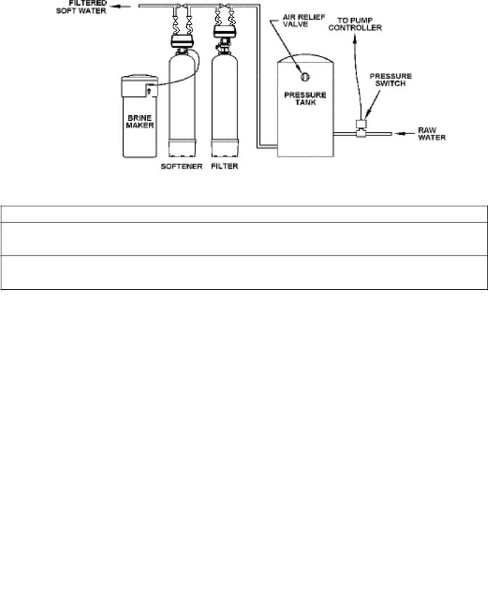
3)Locate in correct relationship to other water conditioning equipment (Figure 1, page 2-1).
4)Locate the softener in the supply line BEFORE the water heater. Temperatures above 110°F (43.3°C) will damage the softener and void the factory warranty.
5)DO NOT install the softener in a location where freezing temperatures occur. Freezing may cause permanent damage and will also void the factory warranty.
6)Allow sufficient space around the installation for easy servicing.
7)Provide a non-switched 110V, 60Hz (220V, 50Hz for specified systems) power source for the control valve.
 WARNING
To reduce the risk associated with ingestion of contaminants:
• Do not use with water that is microbiologically unsafe or of unknown quality without adequate disinfection before or after the system.
CAUTION
To reduce the risk associated with property damage due to water leakage:
•Protect from freezing, relieve pressure and drain system when temperatures are expected to drop below 33°F (0.6°C).
•Do not install on hot water supply lines. The maximum operating water temperature of this filter system is 110°F (43.3°C).
1-2

Facts to Remember While Planning Your Installation:
1)All installation procedures MUST conform to local and state plumbing codes.
2)If lawn sprinkling, a swimming pool, or geothermal heating/cooling or water for other devices/activities are to be treated by the water softener, a larger model MUST be selected to accommodate the higher flow rate plus the backwashing requirements of the water softener. Consult our Customer Service Department at 1-866-990-9785 for alternative instructions if the pumping rate is insufficient.
3)Remember that the water softener INLET is attached to the pipe that supplies water (i.e. runs to the pump) and the OUTLET is the line that runs toward the water heater.
CAUTION
To reduce the risk associated with property damage due to plugged water lines:
•Pay particular attention to correct orientation of control valve. Water flow should match arrow on control valve. The Inlet and Outlet of other water treatment equipment products will vary depending on the control valve brand used.
4)Before commencing the installation it is advisable to study the existing piping system and to determine the size, number and type of fittings required.
 WARNING
To reduce the risk associated with a hazardous voltage:
•If the home electrical system requires use of the cold water system as an electrical safety ground, a jumper must be used to ensure a sufficient ground connection across the filter installation piping — refer installation to qualified personnel.
5)Sweep the floor to eliminate objects that could pierce the brine tank.
IMPORTANT NOTE
Sodium Information: Water softeners utilizing sodium chloride for regeneration add sodium to the water softened water. Persons who are on sodium restricted diets should consider the added sodium as part of their overall sodium intake. As a reference as to how much sodium is added to softened water consider the following. For each grain per gallon of water hardness that is exchanged from the water supply, 7.5 milligrams per liter of sodium will be added to the softened water. e.g. 10 grains per gallon (gpg) exchanged will add 75 milligrams of sodium to the softened water.
1-3
SECTION 2: INSTALLATION
Proper installation sequence of water conditioning equipment is very important. Refer to the following diagram for your particular water supply.
Figure 1
CAUTION
To reduce the risk associated with property damage due to water leakage:
•Read and follow Use instructions before installation and use of this water treatment system.
•Installation and use MUST comply with existing state or local plumbing codes.
To reduce the risk associated with property damage due to plugged water lines:
•Pay particular attention to correct orientation of control valve. Water flow should match arrow on control valve. The Inlet and Outlet of other water treatment equipment products will vary depending on the control valve brand used.
Step 1
(a)Remove control valve by removing quick connect clamp and using a garden hose or bucket, to fill SOFTENER TANK with water (this filling method prevents air entrapment that can cause loss of resin during initial regeneration procedure). Replace control valve. Make sure clamp is reassembled as shown in Figure 2 "LATCH" arrows should point toward each other.
(b)Attach BYPASS VALVE/YOKE ASSEMBLY (Figure 3) using ADAPTER COUPLINGS, CLIPS and SCREWS to CONTROL VALVE (Figure 4). On Meter initiated models, attach METER between BYPASS VALVE and CONTROL VALVE (Figure 4).
Step 2
Shut off all water at main supply valve. On a PRIVATE WELL SYSTEM, turn off power to pump and drain pressure tank. Make certain pressure is relieved from complete system by opening nearest faucet to drain system.
CAUTION |
|
|
To reduce the risk associated with property damage due to water leakage: |
|
|
• SHUT OFF FUEL OR ELECTRIC POWER SUPPLY TO WATER HEATER after water is shut off. |
|
|
|
Figure 2. CLAMP ASSEMBLY |
|
Step 3 |
||
|
||
Cut main supply line as required to fit plumbing INLET and OUTLET of BYPASS VALVE ASSEMBLY. |
|
|
Use flexible tubing connections to connect the valve to household plumbing (as shown in sche- |
|
|
matic). |
|
|
Step 4 |
|
Solder or solvent weld plumbing. DO NOT apply heat to any fitting connected to BYPASS or
CONTROL VALVE as damage may result to internal parts or connecting adapters. MAKE CERTAIN
WATER FLOW ENTERS THROUGH INLET AND DISCHARGES THROUGH OUTLET.
2-1
 Loading...