


Instructions
SC & FC/PC3 Pull-Proof
Fiber Optic Connectors
Termination Procedures for Single-mode and Multimode Field-Mountable Connectors using Epoxy
Issue 1, May 1993
Contents:
A) Warnings, Recommendations and Overview ................................................................................................ |
|
|
|
|
3 |
||||
B) |
Jacketed Cable Preparation .......................................................................................................................... |
|
|
|
|
|
5 |
||
C) |
Mounting........................................................................................................................................................ |
|
|
|
|
|
|
8 |
|
D) |
Scoring .......................................................................................................................................................... |
|
|
|
|
|
|
12 |
|
E) Standard Polishing Process for Single-mode and Multimode Connectors (>30dB) ..................................... |
13 |
||||||||
F) |
Polishing Process for Single-mode Connector Return Loss >40dB ............................................................. |
|
16 |
||||||
G) |
Final Cleaning ............................................................................................................................................... |
|
|
|
|
|
|
20 |
|
H) Mounting Unjacketed/900 ϑm Buffered Fiber |
............................................................................................... |
|
|
|
20 |
||||
I) |
Connector Assembly and Installation ............................................................................................................ |
|
|
|
|
|
22 |
||
J) 3M SC and FC/PC3 Epoxy Field Termination Kits ........................................................................................ |
|
|
|
24 |
|||||
|
|
|
|
|
|
|
|
|
|
|
|
|
|
|
.972 in. |
|
|
|
|
|
|
|
.068 in. |
|
(24.7 |
|
|
|
|
|
|
|
|
mm) |
|
|
|
|
|
|
|
|
(1.73 mm) |
|
.205 in. |
|
|
|
|
|
|
|
|
(5.2 mm) |
|
|
|
||
|
|
|
|
|
|
|
|
||
|
|
.352 in. |
|
|
|
|
|
|
|
|
|
(8.94 mm) |
|
|
|
|
|
|
|
|
|
.289 in. |
|
Key-Shell |
|
|
|
|
|
|
|
|
|
|
|
|
|
||
|
|
(7.34 mm) |
|
|
|
|
|
|
|
|
|
|
.218 in. |
|
|
|
|
|
|
|
|
|
(5.54 mm) |
|
SC Connector |
|
|
|
|
|
|
.266 in. |
|
.289 in. |
Crimp Ring |
Boot |
|
||
|
|
(6.75 mm) |
|
(7.34 mm) |
|
|
|
||
|
|
.283 in. |
|
|
|
|
|
|
|
|
|
(7.19 mm) |
|
|
|
|
|
|
|
|
|
|
Ø .0984 in. |
.925 in. |
|
|
1.97 in. |
|
|
|
|
.235 in. |
(2.499 mm) |
|
|
(50.0 mm) |
|
||
|
|
(23.5 mm) |
|
|
|
||||
|
|
|
|
|
|
|
|||
|
|
(5.97 mm) |
|
|
|
|
|
|
|
|
|
|
|
|
SC Connector |
|
|
||
|
|
|
|
|
|
|
|
|
|
|
|
|
|
|
|
|
|
|
|
|
|
|
Ø .094 in. |
FC/PC3 |
|
|
|
|
|
|
|
|
Connector |
|
|
|
|
||
|
|
|
(2.499 |
Crimp Ring Boot |
|
|
|||
|
|
|
|
|
|
|
|||
|
|
|
mm) |
|
|
|
|
|
|
|
|
Ø .386 in. |
Ø .234 in. |
|
|
|
|
|
|
|
|
(9.8 mm) |
(5.94 mm) |
|
|
|
|
|
|
|
|
|
.154 in. |
|
|
|
|
1.66 in. |
|
|
|
|
|
|
|
|
(15.0 mm) |
|
|
|
|
|
(3.9 mm) |
|
|
|
|
|
|
|
|
|
|
|
|
|
|
|
|
|
|
|
|
.925 in. |
|
|
|
|
|
|
|
|
|
(23.5 mm) |
|
|
|
|
|
2.27 in.
(57.7 mm)
FC/PC3 Connector
2
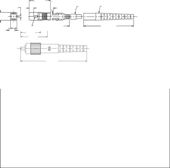
SECTION A
Warnings, Recommendations and Overview
1.Most fibers can be mechanically stripped without the aid of chemicals or heat. If the fiber is not mechanically strippable, contact 3M's Training Department or the cable manufacturer for their recommendations.
2.The recommended cleaning solvent for connectors and tools is isopropyl alcohol (reagent grade, 99% or better). It may be purchased from laboratory supply companies. Isopropyl alcohol may also be used to clean the lapping acetate and stripping tool when necessary. Do not use acetone for cleaning.
3.For safety reasons, no chemicals have been shipped with the 3M brand Field Termination Kit. We have, however, included bottles for the alcohol and water.
Note: Carefully follow safety,health and disposal information on container label or Material Safety Data Sheet for isopropyl alcohol being used.
4.Please contact the 3M Telecom Systems Training Department if you have any questions concerning chemicals or procedures.
Warning: Do not view fiber ends if they are laser illuminated. Eye damage may result. Illuminate fiber ends with white light only.
5.The connectors described in this manual have pre-radiused PC "domed" ferrule ends to ensure low attenuation and the best reflection performance. All polishing should be done on the soft polishing pad only, as described in this manual.
6.The 3M brand connectors with PC finishes are completely intermateable with flat finished connectors. PC to flat terminations actually provide improved performance over flat to flat terminations. PC to PC terminations as produced while using this manual, however, offer the best performance.
7.Safety glasses should be worn when working with optical fibers.
8.Appropriate containers of clean, dry, compressed air may be obtained from photographic supply stores. Do not use types that leave a residue.
3
SECTION A
Warnings, Recommendations and Overview
This manual is for terminating the following field mountable connectors:
|
|
|
|
|
Identification |
|
SC Single-mode |
Product Number |
Housing (Color) |
Ferrule Collar |
Strain Relief Boot |
||
125 ϑm |
8305 |
|
|
Blue |
Black |
White |
126 ϑm |
8306 |
|
|
Blue |
Yellow |
White |
127 ϑm |
8307 |
|
|
Blue |
Silver |
White |
SC Multimode |
|
|
|
|
|
|
125 ϑm |
6306 |
|
|
Beige |
Black |
Beige |
FC Single-mode |
|
|
|
|
|
|
125 ϑm |
8202 |
|
|
Gray |
Black |
White |
126 ϑm |
8203 |
|
|
Gray |
Yellow |
White |
127 ϑm |
8204 |
|
|
Gray |
Silver |
White |
FC Multimode |
|
|
|
|
|
|
125 ϑm |
6202 |
|
|
Beige |
Black |
Beige |
Field Termination Kits |
|
|
|
|
|
|
Field Termination Kit for SC & FC/PC3 Connectors (110V) |
8350 |
|
||||
Field Termination Kit for SC & FC/PC3 Connectors (220V) |
8351 |
|
||||
(See section J for kit listing) |
|
|
|
|
|
|
|
SC Connector |
|
|
|
FC/PC3 |
|
|
|
|
|
|
Connector |
|
(A) |
(D) |
|
|
(A) |
|
(C) |
|
|
|
|
|||
|
(C) |
|
|
|
|
|
|
(B) |
|
|
|
(B) |
|
|
|
|
|
|
|
|
|
|
|
|
|
|
|
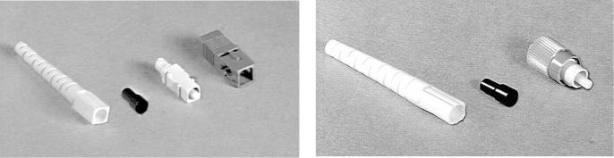
(A)- Strain Relief Boot
(B)- Crimp Ring
(C)- Connector
(D)- Housing
4
SECTION B
Jacketed Cable Preparation
This section is for mounting the 3M brand SC and FC/PC3 fieldmountable connectors on 2.4 mm cable and 3.0 mm cable.
The process for mounting on 900 ϑm buffered fiber can be found in
Section H.
1.TURN THE OVEN ON
Fig. B1
When the oven is heated to the proper temperature the heater light will go off.
2.ASSEMBLE THE CURING STAND ACCORDING TO FIGURE B11
3.PREPARE CONTAINERS AS LABELED
a.Fill one bottle with isopropyl alcohol (reagent grade).
b.Fill one bottle with water.
Note: Carefully follow safety, health and disposal information on container label or Material Safety Data sheet for isopropyl alcohol being used.
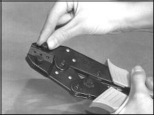
4.PREPARE THE CRIMP TOOL
Included in the field termination kit is a crimp tool set. The package includes a base tool and three die sets to be used as follows:
Die Marking |
Cavity Marking |
Application |
BIC/ST |
.151 |
ST* Bayonet, FC-1 & Biconic |
|
.213 |
TECS 200/230 connector |
|
.178 |
Not used |
SC / FC3 |
.120 |
2.4 mm Jacketed Cable |
|
.137 |
3.0 mm Jacketed Cable |
|
.190 |
Kevlar crimp |
PPST (Push-Pull ST) |
.120 |
2.4 mm Jacketed Cable |
|
.137 |
3.0 mm Jacketed Cable |
|
.226 |
Kevlar crimp |
Select the jaw labeled "SC/FC3." Secure the jaws loosely with the thumb screws. Close the jaws to the fully closed position allowing the jaws to align, then tighten the screws (Fig. B1).
5
SECTION B
Jacketed Cable Preparation
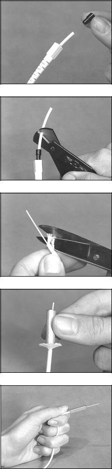
5.SLIP THE STRAIN RELIEF BOOT AND THE CORRECT CRIMP RING ONTO THE CABLE
DO NOT FORGET TO DO THIS STEP. The boot will not fit over a mounted connector assembly so it is essential that it be slipped onto the cable at this time. Slip the smaller diameter of the boot onto the cable first.
Red crimp rings for 2.4 mm cable and black crimp rings for 3.0 mm cable are provided with each connector. Slide the appropriate crimp ring onto the cable, small opening first (Fig. B2).
6.CUT AND REMOVE 1 3/16" (30 mm) OF THE CABLE'S OUTER JACKET
Adjust the yellow handled stripper to cut the jacket and not the Kevlar1.
Using the ruler supplied in the field kit, measure and mark the cable 1 3/16" (30 mm) from the end of the jacket. Close the yellow handled stripper on the cable until the outer jacket is cut (Fig. B3). Remove the jacket with your fingers.
7.CUT AND FLARE THE STRENGTH MEMBERS
Gather the Kevlar and pull it off to one side giving it a slight twist. Using the serrated scissors cut the Kevlar leaving about 5/16" (8 mm) sticking out of the outer jacket (Fig. B4). Slip the smaller hole of the blue stripping collar over the buffer and flare out all of the Kevlar evenly (Fig. B5). Reverse the collar and slide the larger hole over the buffer and outer jacket. Push down gently until the stripping collar folds the Kevlar back and seats.
8.HOLD THE CABLE SECURELY
Before stripping the buffer it is important to hold the cable in a configuration which will prevent the buffered fiber from being pulled out of the outer jacket.
Grasp the end of the outer jacket between your thumb and forefinger. Wind the cable between your fingers (Fig.B6). Squeezing with all fingers will clamp the buffered fiber in the outer jacket (Fig. B6).
Fig. B2
Fig. B3
Fig. B4
Fig. B5
Fig. B6
6

SECTION B
Jacketed Cable Preparation
9.BUFFER REMOVAL
With the modified No-Nik tool's arrow pointing in the direction of the stripping, remove the fiber's buffer in small bites, about 3/16" (5 mm).
Be sure to remove the stripped material from the tool after each incremental cut. When stripping the last increment, the end of the stripping collar should gently rest against the fiber guide inside of the clearance hole of the No-Nik (Fig. B7). This will ensure the correct
10.9/16"CLEAN(14THEmm)FIBERbufferWITHlengthALCOHOLremaining.
With the collar still in place, moisten a lint free cloth with isopropyl alcohol from the bottle and wipe the fiber clean (Fig. B8). Make sure there is absolutely no buffer residue or dirt on the fiber by holding it to a light and inspecting for a smooth shiny surface. If necessary, wipe the fiber a second time to be sure that it is clean.
11.REMOVE THE STRIPPING COLLAR
Remove the stripping collar and position the cut Kevlar so that it is evenly distributed around the buffer. At this time, verify the strip length dimensions. It is very important that the exposed buffer measures 9/16" (14 mm) from the end of the cut jacket as shown in Fig. B9. (Figure not to scale). Confirm all dimensions using the ruler provided (Fig. B10).
12.PROTECT PREPARED FIBERS
Clip the cable in the curing stand where the fiber end will not touch anything (Fig. B11). When mounting more than one connector, prepare all fiber ends before mixing the epoxy.
Fig. B7
Fig. B8
1 |
3/16" |
(30 mm) |
|
9/16" |
|
(14 mm) |
|
Outer Jacket |
|
Kevlar |
|
5/16" (8 mm) |
|
Fig. B9
Fig. B10
Fig. B11
7
SECTION C
Mounting
1.INSPECT THE CONNECTOR
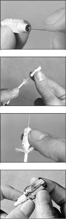
Before mounting, hold the connector up to a light to ensure that the capillary hole of the ceramic ferrule is clear. If the hole is obstructed, blow it clear with air or use a piece of stainless steel wire supplied with the kit. To clear simply insert a wire through the back end of the connector so that the wire forces any debris through the front end of the ceramic ferrule (Fig. C1).
2.MULTIMODE CONNECTOR MOUNTING
The 125 ϑm size connector will fit standard 125 ϑm multimode fibers. Since dry fitting is therefore not necessary, advance to C3 in this section.
For 140 ϑm size fibers contact your local 3M sales representative. SINGLE-MODE CONNECTOR FITTING
In order to achieve the lowest attenuation, it is important to dry fit single-mode connectors onto individual fibers.
Single-mode connectors are available in three closely toleranced ferrules sizes for mounting on single-mode fiber. Refer to page 4 for connector identification.
Select a 125 ϑm size connector. Line up the connector straight with the fiber and thread it onto the fiber while slightly rotating the connector between thumb and forefinger (Fig. C2). Do not try to force the connector onto the fiber. If the ferrule is too tight, the fiber will begin to buckle. If this is the case, carefully remove the 125 ϑm size and select a 126 ϑm size connector. Check to see that the ferrule hole is clear and dry fit. If the 126 ϑm size is too tight then a 127 ϑm connector should be used. If the connector cannot be threaded onto the fiber, re-inspect the fiber and the connector. Re-clean if necessary.
Note: At times when fitting connectors, a fiber particle may become lodged in the ferrule. In order to clear the ferrule it may be necessary to insert a stainless steel wire through the front of the ferrule and push the fiber out through the rear. Be sure to blow the connector clean after using the wire.
Slide the correct size connector all the way onto the fiber until the buffer bottoms against the ferrule. At this point, there should be no more than 1/16" (2 mm) space between the end of the cable and the back end of the connector (Fig. C3). After the fit is confirmed, carefully remove the connector from the fiber and place the fiber in the curing stand.
3.INSTALL THE LOAD ADAPTER ONTO THE CONNECTOR
After the connector has been fitted, insert it into the load adapter (Fig. C4) and place the connector in the stand with its matching fiber.
Fig. C1
Fig. C2
Fig. C3
Fig. C4
8
 Loading...