


MP7640I
Table of contents
 Loading...
MP7640i
Multimedia Projector
Operator's Guide
MP7640i Projecteur multimedia - Guide de L' opérateur
MP7640i Multimedia-Projektor - Benutzerhandbuch
MP7640i Proyector de Multimedia - Guía del usuario
MP7640i Proiettore Multimediale - Guida dell' operatore
MP7640i Multimedia Projector - Gebruiksaanwijzing
MP7640i Projector dos Multimedia - Guia da operador
MP7640i Multimedia Projektør- Brukerhåndbok

Intended Use Statement
Before operating this machine, please read the Operator’s Guide and
Product Safety Guide thoroughly. The 3M™ Multimedia Projectors are
designed, built, and tested for use indoors, using 3M lamps, 3M ceiling
mount hardware, and nominal local voltages. The use of other
replacement lamps, outdoor operation, or different voltages have not
been tested and could damage the projector peripheral equipment and/or
create a potentially unsafe operating condition. 3M Multimedia
projectors are designed to operate in a normal office environment.
• 16° to 29°C (60° to 85° F)
• 10-80 % RH (without condensation)
• 0-1828 m (0-6000 feet) above sea level
The ambient operating environment should be free of airborne smoke,
grease, oil and other contaminates that can affect the operation or
performance of the projector.
Use of this product in adverse conditions will
void the product warranty.

ENGLISH
Multimedia Projector
Operator's Guide
Operator's Guide
ENGLISH-1
Thank you for purchasing this liquid crystal projector.
CONTENTS
CONTENTS
Page
FEATURES .......................................2
BEFORE USE ...................................2
Contents of Package ..............................2
Part Names.............................................3
Loading the Battery ................................4
INSTALLATION ................................5
Installation of the Projector and Screen
........5
Angle Adjustment ...................................5
Cabling ...................................................6
Power Connection ..................................7
Example of System Setup ......................7
Plug & Play.............................................7
OPERATIONS...................................8
Power On...................................................8
Power Off
................................................8
Basic Operation......................................9
Setup Menu ..........................................11
Input Menu............................................12
Image Menu..........................................13
Options Menu .......................................14
No Signal Menu....................................15
MAINTENANCE ..............................16
Lamp.....................................................16
Air Filter ................................................18
Other Maintenance...............................18
Page
TROUBLESHOOTING ....................19
Service Infomation................................19
OSD Message ......................................19
Indicators Message ..............................20
Symptom ..............................................21
SPECIFICATIONS...........................22
ACCESSORIES...............................23
TABLES
Table 1. Installation Reference.................5
Table 2. Cabling .......................................6
Table 3. Basic Operations ........................9
Table 4. Setup Menu ..............................11
Table 5. Input Menu................................12
Table 6. Image Menu..............................13
Table 7. Options Menu ...........................14
Table 8. No Signal Menu........................15
Table 9. OSD Message ..........................19
Table 10. Indicator Message ..................20
Table 11. Symptom ................................21
Table 12. Specifications .........................22
.......................................................................................
For "TECHNICAL" and "REGULATORY
NOTICE", see the end of this manual.
• The information in this manual is subject to change without notice.
• The manufacturer assumes no responsibility for any errors that may appear in this manual
• The reproduction, transmission or use of this document or contents is not permitted without
express written authority.
TRADEMARK ACKNOWLEDGMENT : PS/2, VGA and XGA are registered trademarks of
International Business Machines Corporation. Apple, Mac and ADB are registered trademarks of
Apple Computer, Inc. VESA and SVGA are trademarks of the Video Electronics Standard
Association. Windows is a registered trademark of Microsoft Corporation. Carefully observe the
trademarks and registered trademarks of all companies, even when not mentioned.
NOTE
WARNING • Please read the accompanying manual “Product Safety Guide”
and this “Operator's Guide” thoroughly to ensure correct usage through
understanding. After reading, store this instruction manual in a safe place for
future reference.
TECHNICAL APPENDIX.......................24
ENGLISH-2
FEATURES
FEATURES
This liquid crystal projector is used to project various computer signals as well as NTSC / PAL /
SECAM video signals onto a screen. Little space is required for installation and large images can
easily be seen.
Outstanding Brightness
The UHB lamp and high-efficiency optical system assure a high level of brightness.
Partial Magnification Function
Interesting parts of images can be magnified for closer viewing.
Distortion Correction Function
Distortion-free images are quickly available.
Extra-low Noise Function
Acoustic noise level from the unit can be reduced.
BEFORE USE
BEFORE USE
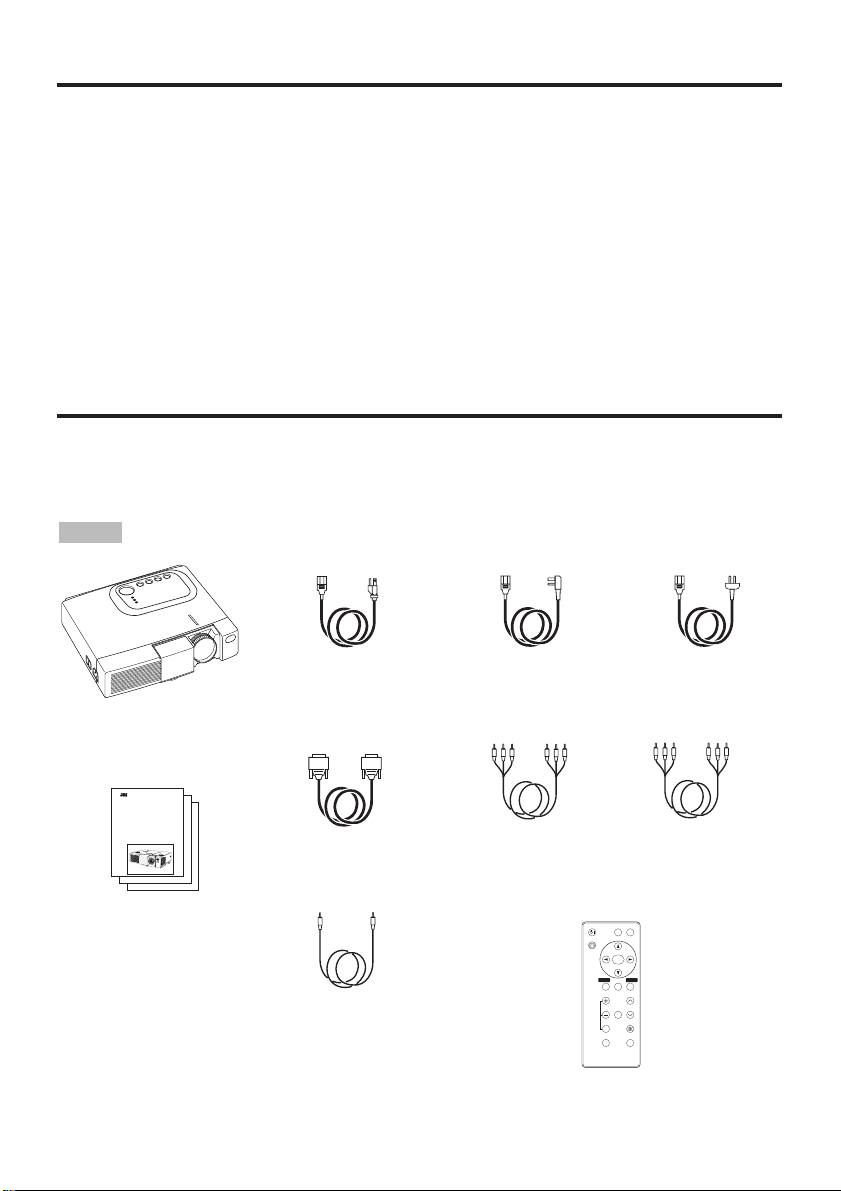
Contents of package
Make sure all of the following items are included in the package. If anything is missing, please
contact your dealer.
• Keep the original packing material for future reshipment.
NOTE
Projector
Power Cord
(US Type)
Power Cord
(UK Type)
Power Cord
(Europe Type)
RGB Cable
VIDEO
STANDBY/ON
KEYSTONE
POSITION
FREEZE
MAGNIFY
VOLUME
AUTO
OFF
BLANK
MENU
SELECT
RGB
MUTE
MENU RESET
Component
Video Cable
Remote Control
Transmitter
containing Battery
Operator's Guide
Product Safety Guide
Quick Start Guide
MP8647
Multimedia Projector
Operator's Guide
MP8647 Projecteur multimedia - Guide de I' opérateur
MP8647 Multimedia-Projektor - Benutzerhandbuch
MP8647 Proyector de Multimedia - Guía del usuario
MP8647 Proiettore Multimediale - Guida dell' operatore
MP8647 Projector dos Multimedia - Guia da operador
MP8647 Multimedia Projector - Gebruiksaanwijzing
Video/Audio
Cable
Stereo mini
jack cable
ENGLISH-3
BB
BB
EE
EE
FF
FF
OO
OO
RR
RR
EE
EE
UU
UU
SS
SS
EE
EE
((
((
cc
cc
oo
oo
nn
nn
tt
tt
ii
ii
nn
nn
uu
uu
ee
ee
dd
dd
))
))
ENGLISH
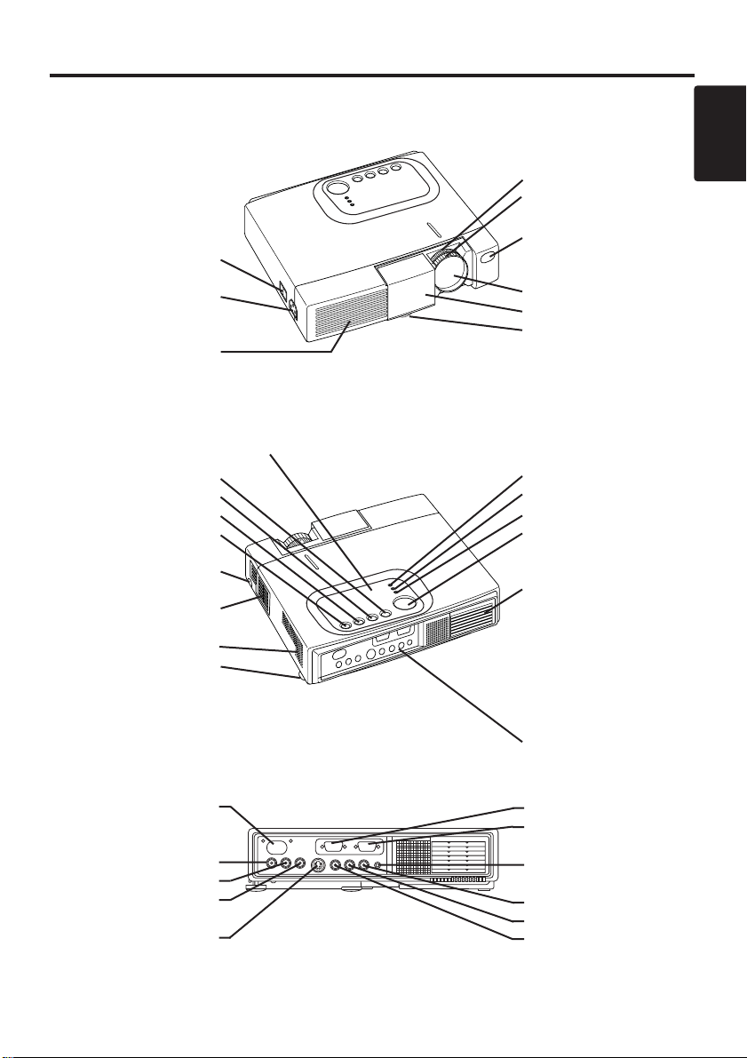
Part Names
Power Switch
AC Inlet
(to the Power Cord)
Ventilation Openings
(Intake)
Zoom Knob
Focus Ring
Remote Control Sensor
Lens
Slide Lens Door
Foot Adjuster
Front / Left / View
RESET Button
KEYSTONE Button
INPUT Button
STANDBY/ON Button
Foot Adjuster Button
Air Filter and Intake
(for the Cooling Fan)
Speaker
Rear Foot Adjuster
LAMP Indicator
TEMP Indicator
POWER Indicator
MENU Button
Ventilation Openings
(Exhaust)
Rear / Right / View
Terminal Panel
(Refer below)
Remote Control Sensor
COMPONENENT
Y Terminal
C
B/PB Terminal
C
R/PR Terminal
S-VIDEO Terminal
RGB Terminal
CONTROL Terminal
AUDIO Terminal
AUDIO
R Terminal
L Terminal
VIDEO Terminal
Terminal Panel
Control Panel (Refer to P.8 "OPERATIONS")

ENGLISH-4
BB
BB
EE
EE
FF
FF
OO
OO
RR
RR
EE
EE
UU
UU
SS
SS
EE
EE
((
((
cc
cc
oo
oo
nn
nn
tt
tt
ii
ii
nn
nn
uu
uu
ee
ee
dd
dd
))
))
Part Names (continued)
VIDEO
STANDBY/ON
KEYSTONE
POSITION
FREEZE
MAGNIFY
VOLUME
AUTO
OFF
BLANK
MENU
SELECT
RGB
MUTE
MENU RESET
STANDBY/ON Button
KEYSTONE Button
Button
Button
Button
Button
MENU Button
MAGNIFY Button
MAGNIFY Button
MAGNIFY Button
AUTO Button
Battery Holder
OFF
VIDEO Button
RGB Button
MENU SELECT Button
POSITION Button
RESET Button
VOLUME Button
VOLUME Button
FREEZE Button
MUTE Button
BLANK Button
Remote Controller
Loading the Battery
First Loading:
In original packing, the battery is installed in the battery holder
of the remote control transmitter with protection film
Pull out the protection film to activate the battery.
Replacing:
1. See the reverse side of the remote control transmitter.
2. Press the grove in and pull out battery holder as shown to the right.
3. Remove the old battery.
4. Install the new battery (3V micro lithium battery type no.CR2025)
with “+” side facing.
5. Push in and click the battery holder.
Pull out
“+” side
Battery Holder
(Refer to Page.8 "OPERATIONS")
Replace the batteries when remote control transmitter operation becomes difficult.
NOTE
CAUTION • Incorrect handling of the battery could result in fire or personal injury.The
battery may explode if not handled properly. Be careful handling the battery.
Follow the instructions in both the "Product Safety Guide" and this manual.
• Use the 3V micro lithium battery type no.CR2025 only.
• When loading the battery, make sure the plus and minus terminals are correctly oriented as
indicated in the remote control transmitter.
• When you dispose the battery, you should obey the law in the relative area or country.
• Keep the battery away from children and pets.
• When not to be used for an extended period, remove the battery from the remote control
transmitter.

ENGLISH-5
ENGLISH
INSTALLATION
INSTALLATION
Installation of the Projector and Screen
Refer to the drawing and table below for determining the screen size and projection distance.
Angle Adjustment
Use the foot adjusters on the bottom of
the projector to adjust the projection
angle. It is variable within 0˚ to 10˚
approximately.
1. Lift up the front side of the projector,
and pressing the foot adjuster button,
adjust the projection angle.
2. Release the button to lock at the
desired angle.
3. Use the rear foot adjuster to adjust the
left-right slope.
The projection distances shown in the table below
are for full size (800 x 600 dots).
a: Distance from the projector to the screen. (±10%)
b: Distance from the lens center to the bottom of the
screen. (±10%)
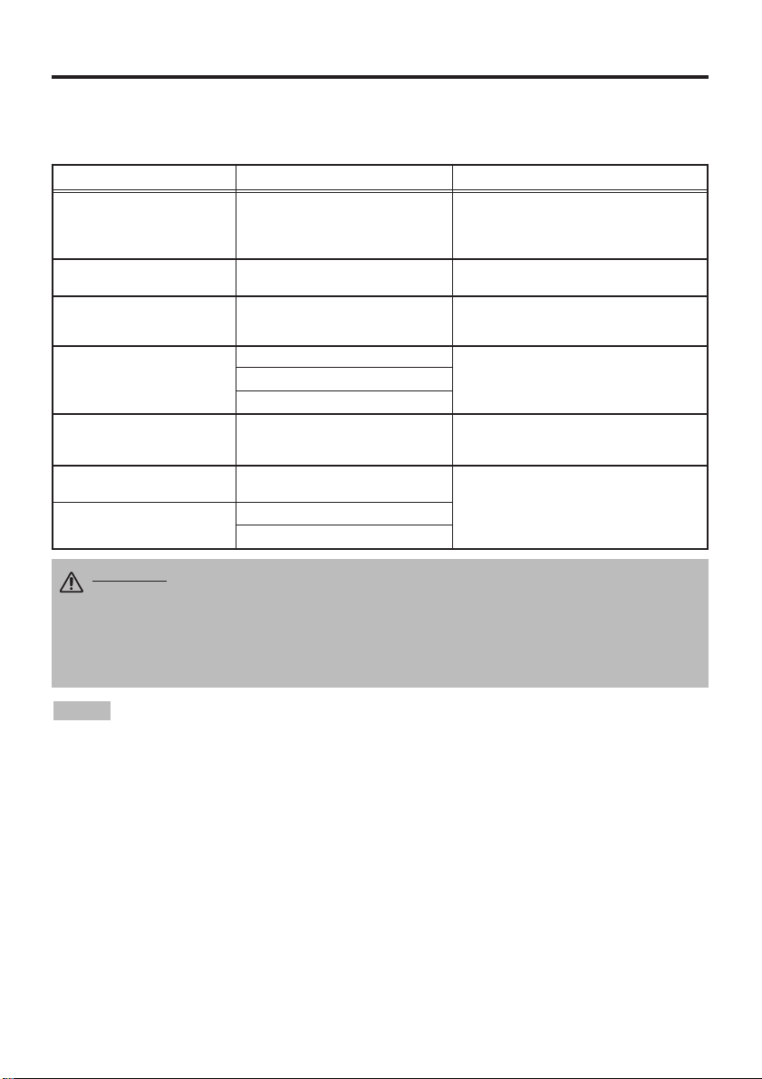
Table 1. Installation Reference
Screen
CAUTION • Install the projector in a suitable environment according to
instructions of the accompanying manual “Product Safety Guide” and this
manual.
• Please use liquid the projector at the horizontal position.
If you use the projector
by the lens up position, the lens down position and the side up position, this may
cause the heat inside to build up and cause damage.
Be especially careful not install
it with ventilation holes blocked.
• Do not install LCD projector in smoke effected environment. Smoke residue may
buildup on critical parts (i.e.LCD panel, Lens Assy etc.).
CAUTION • Do not release the foot adjuster button unless the projector is
being held; otherwise, the projector could overturn or fingers could get
caught and cause personal injury.
TOP VIEW
SIDE VIEW
a
b
Foot Adjuster
Press the foot adjuster button
Rear Foot Adjuster
Lens
center
Screen size
[inches (m)]
a [inches (m)]
b
[inches (cm)]
Min. Max.
40 (1.0) 37 (0.9) 46 (1.2) 3 (8.7)
60 (1.5) 57 (1.5) 69 (1.8) 5 (13.1)
80 (2.0) 77 (1.9) 93 (2.4) 7 (17.4)
100 (2.5) 96 (2.4) 116 (2.9) 9 (21.8)
120 (3.0) 116 (2.9) 139 (3.5) 10 (26.1)
150 (3.8) 145 (3.7) 174 (4.4) 13 (32.7)
200 (5.0) 194 (4.9) 233 (5.9) 17 (43.5)
ENGLISH-6
II
II
NN
NN
SS
SS
TT
TT
AA
AA
LL
LL
LL
LL
AA
AA
TT
TT
II
II
OO
OO
NN
NN
((
((
cc
cc
oo
oo
nn
nn
tt
tt
ii
ii
nn
nn
uu
uu
ee
ee
dd
dd
))
))
• Before connecting, read instruction manuals of the devices to be connected, and make sure that the
projector is compatible with the device.
• Secure the screws on the connectors and tighten.
• For some RGB input modes, the optional Mac adapter is necessary.
• Some computers may have multiple display screen modes. Use of some of these modes will not be possible
with this projector.
• Refer to the “TECHNICAL” section for the pin assignment of connectors and RS-232C communication data.
• For others, consult your dealer.
NOTE
CAUTION • Incorrect connecting could result in fire or electrical shock.
Please read this manual and the separate “
Product Safety Guide
”.
• Before connecting, turn off to all devices to be connected, except for the USB
cable.
• The cables may have to be used with the core set to the projector side. Use the
cables which are included with the projector or specified.
Cabling
Refer to the table below for connecting each terminal of the projector to a device.
Table 2. Cabling
Function Terminal Cable
Analog RGB input RGB
Accessory RGB cable or optional RGB
cable with D-sub 15-pin shrink jack and
inch thread screws
RS-232C communication CONTROL Optional RS-232C cable
Audio input
(from the computer)
AUDIO Optional audio cable with stereo mini jack
Component video input
COMPONENT VIDEO Y
Accessory component video cable
COMPONENT VIDEO CB/PB
COMPONENT VIDEO CR/PR
S-video input S-VIDEO
Optional S-video cable with mini DIN 4-pin
jack
Video input VIDEO
Optional video/audio cable with RCA jack
Audio input
(from video equipment)
AUDIO L
AUDIO R
ENGLISH-7
ENGLISH
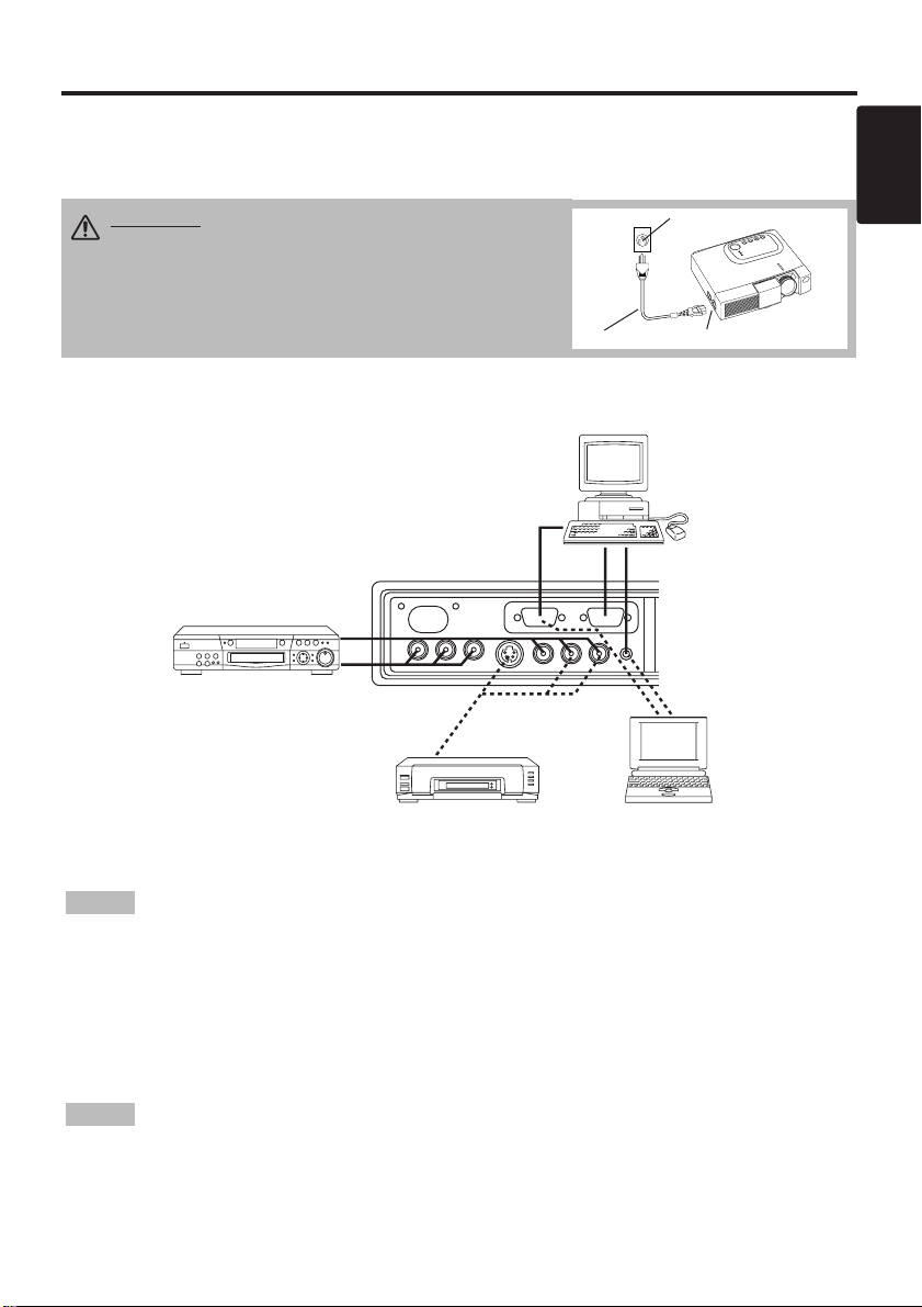
Example of system setup
S-Video Tape
Recorder
Computer
(notebook type)
• When connecting with a notebook computer, set the proper RGB external image output
(setting CRT display or simultaneous display of LCD and CRT). Please read instruction manual of
the notebook for more information.
Plug & Play
This projector is VESA DDC 1/2B compatible. Plug & play is possible by connecting to a computer
that is VESA DDC (Display Data Channel) compatible.
Please use this function by connecting the accessory RGB cable with RGB terminal. Plug & play
may not operate by other connections.
• Plug & play is a system configured with peripheral equipment including a computer,
display and an operating system.
• This projector is recognized as a plug & play monitor. Use the standard display drivers.
• Plug & play may not operate by the computer to connect. Plug & play will not operate in the
connection with Apple computer.
NOTE
NOTE
II
II
NN
NN
SS
SS
TT
TT
AA
AA
LL
LL
LL
LL
AA
AA
TT
TT
II
II
OO
OO
NN
NN
((
((
cc
cc
oo
oo
nn
nn
tt
tt
ii
ii
nn
nn
uu
uu
ee
ee
dd
dd
))
))
Power Connection
Use the correct power cord depending on the power outlet to be used.
Connect the AC inlet of the projector to the power outlet firmly by the power cord.
AC Inlet
Power Cord
Power outlet
CAUTION • Exercise caution while using the
power cord. Follow the instructions in the
accompanying manual "
Product Safety Guide
" and
this manual.
• Connect the power cord firmly. Avoid using a
loose, unsound outlet or failed contact.
Computer
(desktop type)
DVD Player
ENGLISH-8
OPERATIONS
OPERATIONS
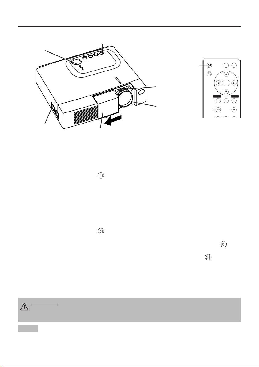
Power ON
1. Check that the power cord is connected correctly.
2. Set the power switch to [ | ]. The standby mode is selected, and the POWER indicator lights
orange.
3. Press the STANDBY/ON button on the control panel or the remote controller. Warm-up
begins and the POWER indicator blinks green.
4. The POWER indicator ceases blinking and remains green when power is on. Open the slide lens
door.
5. Adjust picture size using the Zoom knob.
6. Adjust focus using the Focus ring.
Power OFF
1. Press the STANDBY/ON button on the control panel or the remote controller. Then, the
message "Power off?" will appear on the screen,and the message will disappear by any operation
or no operation for 5 seconds.During this messsage indication,press the STANDBY/ON
button again. The projector lamp is extinguished and lamp cooling begins. The POWER
indicator blinks orange during lamp cooling. Pressing the STANDBY/ON button has no
effect while the POWER indicator is blinking.
2. The system assumes the Standby mode when cooling is complete, and the POWER indicator
ceases blinking and changes to orange. Check that the indicator is orange and set the Power
switch to [
O
].
3. The POWER indicator is extinguished when power is off. Do not forget to close the lens door.
• Except in emergencies, do not turn off unless the POWER indicator is orange as it will
reduce the life of the projector lamp.
• To prevent any troble, turn on/off the projector when the computer or video tape recorder is OFF.
Providing a RS-232C cable is connected, turn on the computer before the projector.
NOTE
WARNING • Please read this manual, and the separate “SAFETY
INSTRUCTIONS” thoroughly before using the equipment. Always ensure that
the equipment is used safely.
Power Switch
Slide Lens door
STANDBY/ON Button
POWER Indicator
VIDEO
STANDBY/ON
KEYSTONE
POSITION
FREEZE
MAGNIFY
VOLUME
MENU
SELECT
RGB
MENU RESET
STANDBY/
ON Button
Zoom knob
Focus ring
ENGLISH-9
ENGLISH
OO
OO
PP
PP
EE
EE
RR
RR
AA
AA
TT
TT
II
II
OO
OO
NN
NN
SS
SS
((
((
cc
cc
oo
oo
nn
nn
tt
tt
ii
ii
nn
nn
uu
uu
ee
ee
dd
dd
))
))
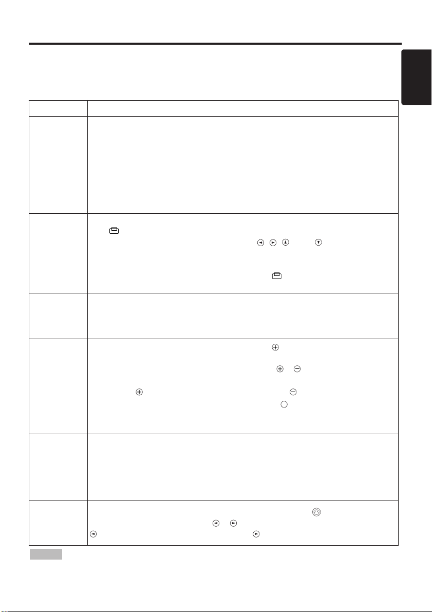
Basic Operation
The basic operations shown in Table 3 is performed from the supplied remote controller or the
projector control panel. Items indicated by (*) may be used from the control panel.
Table 3 . Basic Operation
Item Description
INPUT
SELECT
Select Input Signal (*) : Press the INPUT button.
RGB→ VIDEO → S-VIDEO → COMPONENT (→ RGB)
Select RGB Input : Press the RGB button.
VIDEO/S-VIDEO/COMPONENT → RGB
Select Video Input : Press the VIDEO button.
RGB → VIDEO/S-VIDEO/COMPONENT
VIDEO → S-VIDEO → COMPONENT (→ VIDEO)
• The selected signal name is displayed for approximately 3 seconds when the input
signal is changed.
POSITION
Set/Clear Position Adjustment Mode : Press the POSITION button.
The [ ] icon is displayed in the POSITION mode.
Image Position Adjustment: Press the , , and buttons in the
POSITION mode.
• Valid only in the MAGNIFY mode with a video signal is input.
• After approximately 10 seconds of inactivity the [ ] icon is extinguished and the
POSITION mode is cleared automatically.
RESET (*)
Initialize Each Item : Select an item and press the RESET button.
Initialize Position Adjustment : Press the RESET button and the
POSITION mode. This function is valid only when RGB signal is input.
• Valid except for the VOLUME, LANGUAGE, H PHASE and WIHSPER.
MAGNIFY
Set MAGNIFY Mode : Press the MAGNIFY button.
Move Magnified Area : Run the POSITION in the MAGNIFY mode.
Adjust Magnification : Press the MAGNIFY / button in MAGNIFY
mode.
MAGNIFY magnifies the image ↔ MAGNIFY reduces the image
Clear MAGNIFY Mode : Press the MAGNIFY button.
• The MAGNIFY mode is cleared by running or setting the AUTO, ASPECT, INPUT
SELECT or VIDEO, or by changing the input signal.
OFF
FREEZE
Set/Clear FREEZE Mode : Press the FREEZE button. The [
II
] icon is
displayed, and the image frozen, in the FREEZE mode.
• The FREEZE mode is cleared by running or setting POSITION, VOLUME, MUTE,
Automatic Adjustment, BLANK ON/OFF, or MENU ON/OFF, or by changing the
input signal.
• Do not forget to clear frozen static images.
KEYSTONE
(
*)
Set/Clear KEYSTONE Mode : Press the KEYSTONE button.
Adjust Keystone : Press the / button in the KEYSTONE mode.
reduces the bottom size of image ↔ reduces the top size of image
• Use the remote controller at a distance of approximately 3m from the sensor on the front
of the projector, and within a range of 30° left-right. Strong light and obstacles will interfere with
operation of the remote controller.
NOTE
(It continue the next page.)
ENGLISH-10
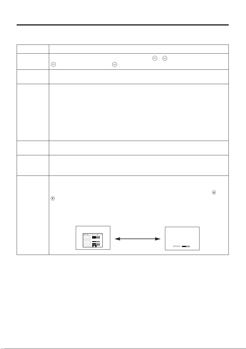
Item Description
VOLUME
Volume Adjustment : Press the VOLUME / button.
reduces the volume
↔ increases the volume
MUTE
Set/Clear Mute Mode : Press the MUTE button. No sound is heard in the
MUTE mode.
AUTO
Automatic Adjustment at RGB Input : Press the AUTO button. Horizontal
position(H.POSIT), vertical position (V.POSIT),clock phase (H.PHASE), and
horizontal size(H.SIZE) are automatically adjusted. Use with the window at
maximum size in the application display.
Automatic Adjustment at Video Input : Press the AUTO button. A signal
type appropriate for the input signal is selected automatically. Valid only
when AUTO is set for VIDEO on the menu.
• This operation requires approximately ten seconds. It may not function correctly
with some input signals.
BLANK
ON/OFF
Set/Clear Blank Mode: Press the BLANK button. No image is displayed in
the Blank mode. The screen color is as set in BLANK on the Image menu.
MENU
ON/OFF (
*)
Menu Display Start/Stop: Press the MENU button.
• The menu display is terminated automatically after approximately ten seconds of
inactivity.
MENU
SELECT
Select Menu Type: Press the MENU SELECT button. Allows the user to
select the normal menu or the single menu. Only the selected item is
displayed on the single menu, and other items are displayed with the and
buttons as with the normal menu.
• Valid only when the Setup menu is used. Push the MENU SELECT button after
selecting items such as "BRIGHTNESS".
Normal menu Single menu
OO
OO
PP
PP
EE
EE
RR
RR
AA
AA
TT
TT
II
II
OO
OO
NN
NN
SS
SS
((
((
cc
cc
oo
oo
nn
nn
tt
tt
ii
ii
nn
nn
uu
uu
ee
ee
dd
dd
))
))
Items indicated by (*) may be used from the control panel.
Table 3. Basic Operation (continued)
CONTRAST
-2
BRIGHT
CONTRAST
V POSIT
H POSIT
H PHASE
H SIZE
COLOR BAL R
COLOR BAL B
ASPECT
0
-2
+1
0
0
100
100
800
SETUP INPUT OPT.IMAGE
(MENU SELECT)
Loading...