


 Loading...
OPERATOR’S MANUAL
MODEL 703E
PHOTOMETRIC O3 CALIBRATOR
© TELEDYNE INSTRUMENTS
ADVANCED POLLUTION INSTRUMENTATION DIVISION (TAPI)
9480 CARROLL PARK DRIVE
SAN DIEGO, CALIFORNIA 92121-5201
USA
Toll-free Phone: |
800-324-5190 |
Phone: |
858-657-9800 |
Fax: |
858-657-9816 |
Email: |
api-sales@teledyne.com |
Website: |
http://www.teledyne-api.com/ |
|
05743 Rev. C |
Copyright 2007 |
DCN 5521 |
Teledyne Advanced Pollution Instrumentation |
29 July 2009 |
THIS PAGE IS INTENTIONALLY LEFT BLANK
PRINTED DOCUMENTS ARE UNCONTROLLED.
We recommend that this document be read in its entirety before any attempt is made to operate the instrument.
DOCUMENTS
Document P/N |
Revision |
DCN |
Nomenclature |
Dated |
|
|
|
|
|
05743 |
B |
5359 |
M703, Manual, Instruction - Title |
03/20/09 |
|
|
|
|
|
05744 |
B |
5359 |
M703, Manual, Instruction - Text |
03/20/09 |
|
|
|
|
|
05745 |
C |
5359 |
M703, Appendix A, Menu Tree |
03/20/09 |
|
|
|
|
|
05746 |
B |
5359 |
M703, Appendix B, Spare Parts |
03/20/09 |
|
|
|
|
|
05747 |
B |
5359 |
M703, Appendix C, Repair Form |
03/20/09 |
|
|
|
|
|
05748 |
B |
5359 |
M703, Appendix D, Schematics |
03/20/09 |
|
|
|
|
|
05834 |
F |
5359 |
List, Spare Parts, M703 |
03/20/09 |
|
|
|
|
|
05863 |
B |
5359 |
List, Recommended Spares Stocking Levels, |
03/20/09 |
|
|
|
M703 |
|
|
|
|
|
|
05834 |
J |
5480 |
List, Spare Parts, M703 |
07/15/09 |
|
|
|
|
|
05863 |
D |
5480 |
List, Recommended Spares Stocking Levels, |
07/15/09 |
|
|
|
M703 |
|
|
|
|
|
|
THIS PAGE IS INTENTIONALLY LEFT BLANK

|
TELEDYNE API |
M703E Calibrator Operator’s Manual |
Safety Messages |
SAFETY MESSAGES
Your safety and the safety of others are very important. We have provided many important safety messages in this manual. Please read these messages carefully.
A safety message alerts you to potential hazards that could hurt you or others. Each safety message is associated with a safety alert symbol. These symbols are found in the manual and inside the M703E Photometric O3 Calibrator. The definition of these symbols is described below:
GENERAL SAFETY HAZARD: Refer to the instructions for details on the specific hazard.
CAUTION: Hot Surface Warning.
CAUTION: Electrical Shock Hazard.
TECHNICIAN SYMBOL: All operations marked with this symbol are to be performed by qualified maintenance personnel only.
CAUTION
The M703E Photometric O3 Calibrator should only be used for the purpose and in the manner described in this manual. If you use the M703E in a manner other than that for which it was intended, unpredictable behavior could ensue with possible hazardous consequences.
NOTE
Technical Assistance regarding the use and maintenance of the M703E or any other Teledyne Instruments product
can be obtained by:
Contacting Teledyne Instruments’ Customer Service Department at 800-324-5190 or
Via the internet at http://www.teledyne-api.com/forms
05744 Rev B |
i |

TELEDYNE API |
|
Safety Messages |
M703E Dynamic Operator’s Manual |
USER NOTES:
ii |
05744 Rev B |

|
TELEDYNE API |
M703E Calibrator Operator’s Manual |
Table of Contents |
TABLE OF CONTENTS |
|
GENERAL INFORMATION....................................................................................................... |
1 |
1. INTRODUCTION .................................................................................................................. |
3 |
1.1. M703E calibrator Overview............................................................................................................................ |
3 |
1.2. Using This Manual ......................................................................................................................................... |
3 |
2. SPECIFICATIONS, APPROVALS AND WARRANTY ......................................................... |
5 |
2.1. Specifications ................................................................................................................................................. |
5 |
2.2. CE Mark Compliance ..................................................................................................................................... |
6 |
2.3. Warranty......................................................................................................................................................... |
7 |
3. GETTING STARTED ............................................................................................................ |
9 |
3.1. Unpacking and Initial Setup ........................................................................................................................... |
9 |
3.1.1. Model 703E calibrator............................................................................................................................ |
10 |
3.2. Electrical Connections ................................................................................................................................. |
13 |
3.2.1. Power Connection.................................................................................................................................. |
13 |
3.2.2. Analog output TEST CHANNEL Connections ....................................................................................... |
13 |
3.2.3. Connecting the Status Outputs.............................................................................................................. |
14 |
3.2.4. Connecting the Control Inputs ............................................................................................................... |
15 |
3.2.5. Connecting the Control Outputs ............................................................................................................ |
17 |
3.2.6. Connecting the Serial Ports ................................................................................................................... |
18 |
3.2.7. Connecting to a LAN or the Internet ...................................................................................................... |
18 |
3.2.8. Connecting to a Multidrop Network........................................................................................................ |
18 |
3.3. Pnenumatic Connections ............................................................................................................................. |
19 |
3.3.1. Dry Air In ................................................................................................................................................ |
19 |
3.3.2. Zero Air In .............................................................................................................................................. |
19 |
3.3.3. Output Manifold...................................................................................................................................... |
20 |
3.3.4. Exhaust .................................................................................................................................................. |
20 |
3.3.5. Measuring An External Ozone Source .................................................................................................. |
20 |
3.4. Initial Operation............................................................................................................................................ |
21 |
3.4.1. START-UP ............................................................................................................................................. |
21 |
3.4.2. Warm Up................................................................................................................................................ |
22 |
3.4.3. Warning Messages ................................................................................................................................ |
22 |
3.4.4. Functional Check ................................................................................................................................... |
24 |
3.4.5. Operating Modes for the O3 Generator.................................................................................................. |
25 |
3.4.5.1. CNST (CONSTANT)....................................................................................................................... |
25 |
3.4.5.2. REF (REFERENCE)....................................................................................................................... |
25 |
3.4.5.3. BNCH (BENCH) ............................................................................................................................. |
25 |
3.4.6. Setting the O3 Generator Mode............................................................................................................. |
25 |
3.4.7. Setting the M703E’s output Flow Rate .................................................................................................. |
26 |
4. FREQUENTLY ASKED QUESTIONS AND GLOSSARY .................................................. |
27 |
4.1. FAQ’s ........................................................................................................................................................... |
27 |
4.2. Glossary ....................................................................................................................................................... |
27 |
5. OPTIONAL HARDWARE AND SOFTWARE..................................................................... |
29 |
5.1. Carrying Strap Handle (OPT 29).................................................................................................................. |
29 |
5.2. Communication Options............................................................................................................................... |
30 |
5.2.1. RS232 Modem Cables (OPTs 60 and 60A) .......................................................................................... |
30 |
5.2.2. ETHERNET Cable (OPT 60B)............................................................................................................... |
30 |
5.2.3. RS-232 Multidrop (OPT 62) ................................................................................................................... |
30 |
5.2.4. Ethernet (OPT 63).................................................................................................................................. |
31 |
5.2.5. Ethernet + Multidrop (OPT 64)............................................................................................................... |
32 |
5.3. Additional Manual (OPT 70)......................................................................................................................... |
32 |
5.4. Extended Warranty (OPT 92) ...................................................................................................................... |
32 |
5.5. NIST Traceable, Primary Standard CERTIFICATION ................................................................................. |
32 |
OPERATING INSTRUCTIONS................................................................................................ |
33 |
6. OPERATING THE M703E CALIBRATOR ......................................................................... |
35 |
6.1. Test Functions.............................................................................................................................................. |
36 |
05744 Rev B |
iii |

TELEDYNE API |
|
|
Table of Contents |
M703E Calibrator Operator’s Manual |
|
6.2. Overview of Operating modes ..................................................................................................................... |
|
37 |
6.3. STANDBY Mode .......................................................................................................................................... |
|
38 |
6.4. General Information about the GENERATE mode ...................................................................................... |
|
39 |
6.4.1. GENERATE AUTO: Basic Generation of Calibration Gas................................................................ |
|
39 |
6.5. AUTOMATIC CALIBRATION SEQUENCES ............................................................................................... |
|
40 |
6.5.1. SETUP SEQ: Programming Calibration Sequences......................................................................... |
|
40 |
6.5.1.1. Activating a Sequence from the M703E Front Panel ..................................................................... |
|
41 |
6.5.1.2. Naming a Sequence....................................................................................................................... |
|
42 |
6.5.1.3. Setting the Repeat Count for a Sequence ..................................................................................... |
|
43 |
6.5.1.4. Using the M703E’s Internal Clock to Trigger Sequences............................................................... |
|
44 |
6.5.1.5. Setting Up Control Inputs for a Sequence...................................................................................... |
|
47 |
6.5.1.6. Setting Up Control Outputs for a Sequence................................................................................... |
|
48 |
6.5.1.7. Setting the PROGRESS Reporting Mode for the Sequences........................................................ |
49 |
|
6.5.2. Adding Sequence Steps ........................................................................................................................ |
|
50 |
6.5.2.1. The Generate Step ......................................................................................................................... |
|
51 |
6.5.2.2. The STANDBY Step....................................................................................................................... |
|
52 |
6.5.2.3. The DURATION Step ..................................................................................................................... |
|
52 |
6.5.2.4. The EXECSEQ Step....................................................................................................................... |
|
53 |
6.5.2.5. The CC OUTPUT Step................................................................................................................... |
|
54 |
6.5.2.6. Deleting or Editing an Individual Step in a Sequence .................................................................... |
|
55 |
6.5.3. Deleting a Sequence ............................................................................................................................. |
|
56 |
6.6. SETUP CFG ............................................................................................................................................ |
|
57 |
6.7. SETUP CLK............................................................................................................................................. |
|
58 |
6.7.1. Setting the internal Clock’s Time and Day............................................................................................. |
|
58 |
6.7.2. Adjusting the internal Clock’s speed...................................................................................................... |
|
59 |
6.8. SETUP PASS .......................................................................................................................................... |
|
60 |
6.9. SETUP DIAG TEST CHAN OUTPUT: Using the TEST Channel Analog Output............................... |
62 |
|
6.9.1. Configuring the TEST CHANNEL Analog Output.................................................................................. |
|
62 |
6.9.1.1. The Analog I/O Configuration Submenu. ....................................................................................... |
|
62 |
6.9.1.2. Selecting a Test Channel Function to Output ................................................................................ |
|
64 |
6.9.1.3. TEST CHANNEL VOLTAGE RANGE Configuration...................................................................... |
|
66 |
6.9.1.4. Turning the TEST CHANNEL Over-Range Feature ON/OFF........................................................ |
67 |
|
6.9.1.5. Adding a Recorder Offset to the TEST CHANNEL ........................................................................ |
|
68 |
6.9.2. TEST CHANNEL CALIBRATION .......................................................................................................... |
|
69 |
6.9.2.1. Enabling or disabling the TEST CHANNEL Auto-Cal Feature....................................................... |
69 |
|
6.9.2.2. Automatic TEST CHANNEL Calibration......................................................................................... |
|
70 |
6.9.2.3. Manual Calibration of the TEST CHANNEL configured for Voltage Ranges ................................. |
72 |
|
6.9.3. AIN Calibration....................................................................................................................................... |
|
74 |
6.10. SETUP MORE VARS: Internal Variables (VARS)............................................................................ |
|
75 |
6.11. Operating the M703E Calibrator as an O3 Photometer ............................................................................. |
|
77 |
6.11.1. Set up for Operating the M703E as an O3 Photometer ....................................................................... |
|
77 |
6.12. SETUP LVL: Setting up and using LEADS (Dasibi) Operating Levels ................................................. |
79 |
|
6.12.1. General Information about LEADS LEVELS ....................................................................................... |
|
79 |
6.12.2. Dot commands..................................................................................................................................... |
|
79 |
6.12.3. Levels................................................................................................................................................... |
|
80 |
6.12.4. Activating an existing LEVEL............................................................................................................... |
|
80 |
6.12.5. Programming New LEVELS ................................................................................................................ |
|
81 |
6.12.5.1. Creating a GENERATE LEVEL.................................................................................................... |
|
82 |
6.12.5.2. Creating a MANUAL LEVEL......................................................................................................... |
|
83 |
6.12.5.3. Editing or Deleting a LEVEL......................................................................................................... |
|
84 |
6.12.6. Configuring LEVEL Status Blocks ....................................................................................................... |
|
86 |
7. OPERATING THE M703E OVER THE SERIAL I/O PORTS.............................................. |
87 |
|
7.1. Using the Analyser’s Communication Ports................................................................................................. |
|
87 |
7.1.1. RS-232 DTE and DCE Communication................................................................................................. |
|
87 |
7.1.2. COMM Port Default Settings and Connector Pin Assignments............................................................. |
88 |
|
7.1.3. COMM Port Baud Rate.......................................................................................................................... |
|
90 |
7.1.4. COMM Port Communication Modes ...................................................................................................... |
|
91 |
7.1.5. COMM Port Testing ............................................................................................................................... |
|
93 |
iv |
|
05744 Rev B |

|
|
TELEDYNE API |
M703E Calibrator Operator’s Manual |
Table of Contents |
|
7.1.6. Machine ID |
............................................................................................................................................. |
94 |
7.1.7. Terminal Operating Modes .................................................................................................................... |
95 |
|
7.1.7.1. Help Commands in Terminal Mode................................................................................................ |
95 |
|
7.1.7.2. Command Syntax ........................................................................................................................... |
96 |
|
7.1.7.3. Data Types ..................................................................................................................................... |
96 |
|
7.1.7.4. Status Reporting............................................................................................................................. |
97 |
|
7.1.7.5. COM Port Password Security......................................................................................................... |
98 |
|
7.2. Remote Access by Modem .......................................................................................................................... |
99 |
|
7.3. Multidrop RS-232 Set Up .......................................................................................................................... |
101 |
|
7.4. RS-485 Configuration of COM2 ................................................................................................................ |
103 |
|
7.5. Remote Access via the Ethernet............................................................................................................... |
105 |
|
7.5.1. Ethernet Card COM2 Communication Modes and Baud Rate........................................................... |
105 |
|
7.5.2. Configuring the Ethernet Interface Option using DHCP ..................................................................... |
105 |
|
7.5.2.1. Manually Configuring the Network IP Addresses........................................................................ |
108 |
|
7.5.3. Changing the Calibrator’s HOSTNAME.............................................................................................. |
110 |
|
7.6. APICOM Remote Control Program........................................................................................................... |
111 |
|
8. M703E CALIBRATION AND VERIFICATION.................................................................. |
113 |
|
8.1. Verifying and Calibrating the M703E’s O3 Photometer............................................................................. |
113 |
|
8.1.1. Setup for VERIFYING AND calibrating the O3 Photometer................................................................ |
113 |
|
8.1.1.1. Calibration Manifold Exhaust/Vent Line ...................................................................................... |
114 |
|
8.1.2. Verifying O3 Photometer Performance ............................................................................................... |
115 |
|
8.1.3. Calibrating the O3 Photometer............................................................................................................ |
116 |
|
8.1.3.1. Photometer Zero Calibration ....................................................................................................... |
116 |
|
8.1.3.2. Photometer Span Calibration ...................................................................................................... |
117 |
|
8.1.4. O3 Photometer Dark Calibration ......................................................................................................... |
118 |
|
8.2. Calibrating the O3 Generator .................................................................................................................... |
119 |
|
8.2.1. O3 Generator Calibration table........................................................................................................... |
119 |
|
8.2.2. Viewing O3 Generator Calibration Points............................................................................................ |
120 |
|
8.2.3. Adding or Editing O3 Generator Calibration Points............................................................................. |
121 |
|
8.2.4. Deleting O3 |
Generator Calibration Points ........................................................................................... |
122 |
8.2.5. Turning O3 |
Generator Calibration Points ON / OFF ........................................................................... |
123 |
8.2.6. Performing an Automatic Calibration of the O3 Generator ................................................................. |
124 |
|
8.3. M703E Gas Pressure Sensor Calibration................................................................................................. |
125 |
|
8.3.1.1. Gas Pressure Sensor Calibration Set Up.................................................................................... |
125 |
|
8.3.2. Calibrating the Regulator and Photometer Pressure Sensors ........................................................... |
127 |
|
8.4. M703E Gas Flow Calibration .................................................................................................................... |
128 |
|
8.4.1. Calibrating the Photometer’s Sample Gas Flow................................................................................. |
129 |
|
8.4.2. Calibrating the OuTput Gas Flow ....................................................................................................... |
130 |
|
8.4.2.1. Output Gas Flow Set Up ............................................................................................................. |
130 |
|
8.4.2.2. Performing an Output Gas Flow Calibration ............................................................................... |
131 |
|
TECHNICAL INFORMATION................................................................................................ |
133 |
|
9. THEORY OF OPERATION............................................................................................... |
135 |
|
9.1. Pneumatic Operation ................................................................................................................................ |
135 |
|
9.1.1. Gas Flow Control ................................................................................................................................ |
135 |
|
9.1.1.1. Flow Control Assemblies............................................................................................................. |
135 |
|
9.1.1.2. Photometer Critical Flow Orifice.................................................................................................. |
135 |
|
9.1.2. Internal Gas Pressure Sensors........................................................................................................... |
136 |
|
9.2. Electronic Operation ................................................................................................................................. |
137 |
|
9.2.1. Overview ............................................................................................................................................. |
|
137 |
9.2.2. CPU .................................................................................................................................................... |
|
138 |
9.2.2.1. Disk On Chip ............................................................................................................................... |
139 |
|
9.2.2.2. Flash Chip ................................................................................................................................... |
139 |
|
9.2.3. Relay PCA |
.......................................................................................................................................... |
140 |
9.2.3.1. Valve Control ............................................................................................................................... |
141 |
|
9.2.3.2. Heater Control ............................................................................................................................. |
141 |
|
9.2.3.3. Relay PCA Status LEDs & Watch Dog Circuitry ......................................................................... |
141 |
|
9.2.3.4. Relay PCA Watchdog Indicator (D1)........................................................................................... |
142 |
|
05744 Rev B |
v |

TELEDYNE API |
|
|
Table of Contents |
M703E Calibrator Operator’s Manual |
|
9.2.4. Motherboard........................................................................................................................................ |
|
143 |
9.2.4.1. A to D Conversion ....................................................................................................................... |
|
143 |
9.2.4.2. Sensor Inputs .............................................................................................................................. |
|
143 |
9.2.4.3. Thermistor Interface .................................................................................................................... |
|
143 |
9.2.4.4. Analog Outputs............................................................................................................................ |
|
143 |
9.2.4.5. External Digital I/O....................................................................................................................... |
|
144 |
9.2.4.6. I2C Data Bus................................................................................................................................ |
|
144 |
9.2.4.7. Power-up Circuit .......................................................................................................................... |
|
144 |
9.2.5. Power Supply and Circuit Breaker...................................................................................................... |
|
145 |
9.2.6. AC Power Configuration ..................................................................................................................... |
|
146 |
9.2.6.1. AC configuration – Internal Pump (JP7)...................................................................................... |
|
146 |
9.3. Front Panel Interface ................................................................................................................................ |
|
147 |
9.3.1.1. Calibrator Status LEDs................................................................................................................ |
|
148 |
9.3.1.2. Keyboard ..................................................................................................................................... |
|
148 |
9.3.1.3. Display......................................................................................................................................... |
|
148 |
9.3.1.4. Keyboard/Display Interface Electronics....................................................................................... |
|
149 |
9.4. Software Operation ................................................................................................................................... |
|
150 |
9.5. O3 generator operation............................................................................................................................. |
|
151 |
9.5.1. Principle of Photolytic O3 Generation ................................................................................................. |
|
151 |
9.5.2. Generator Pneumatic Operation......................................................................................................... |
|
152 |
9.5.3. O3 Generator Electronic Operation ..................................................................................................... |
|
152 |
9.5.3.1. O3 Generator Temperature Control............................................................................................. |
|
154 |
9.6. Photometer Operation............................................................................................................................... |
|
155 |
9.6.1. Measurement Method......................................................................................................................... |
|
155 |
9.6.1.1. Calculating O3 Concentration ...................................................................................................... |
|
155 |
9.6.1.2. The Measurement / Reference Cycle.......................................................................................... |
|
156 |
9.6.1.3. The Absorption Path.................................................................................................................... |
|
158 |
9.6.1.4. Interferent Rejection .................................................................................................................... |
|
158 |
9.6.2. Photometer Layout.............................................................................................................................. |
|
159 |
9.6.3. Photometer Pneumatic Operation ...................................................................................................... |
|
159 |
9.6.4. Photometer Electronic Operation........................................................................................................ |
|
160 |
9.6.4.1. O3 Photometer Temperature Control .......................................................................................... |
|
160 |
9.6.4.2. Pneumatic Sensors for the O3 Photometer ................................................................................. |
|
161 |
10. MAINTENANCE SCHEDULE & PROCEDURES .......................................................... |
|
163 |
10.1. Maintenance Schedule ........................................................................................................................... |
|
163 |
10.2. Performing Leak Checks ........................................................................................................................ |
|
167 |
10.2.1. Pressure Leak Check ....................................................................................................................... |
|
167 |
10.3. Cleaning or replacing the Absorption Tube ............................................................................................ |
|
171 |
10.4. Rebuilding the Dry Air Pump .................................................................................................................. |
|
171 |
10.5. Photometer UV Source Lamp Adjustment.............................................................................................. |
|
172 |
10.6. Photometer UV Source Lamp Replacement .......................................................................................... |
|
173 |
10.7. Adjustment or Replacement of Ozone Generator UV Lamp .................................................................. |
|
174 |
11. GENERAL TROUBLESHOOTING & REPAIR OF THE M703E CALIBRATOR ........... |
177 |
|
11.1. General Troubleshooting ........................................................................................................................ |
|
177 |
11.1.1. Fault Diagnosis with WARNING Messages...................................................................................... |
|
178 |
11.1.2. Fault Diagnosis With Test Functions ................................................................................................ |
|
180 |
11.1.3. Using the Diagnostic Signal I/O Function ......................................................................................... |
|
182 |
11.2. Using the Analog Output Test Channel .................................................................................................. |
|
183 |
11.3. Using the Internal Electronic Status LEDs.............................................................................................. |
|
184 |
11.3.1. CPU Status Indicator ........................................................................................................................ |
|
184 |
11.3.2. Relay PCA Status LEDs ................................................................................................................... |
|
184 |
11.3.2.1. I2C Bus Watchdog Status LEDs ................................................................................................ |
|
184 |
11.3.2.2. O3 Status LEDs ......................................................................................................................... |
|
185 |
11.4. Subsystem Checkout.............................................................................................................................. |
|
186 |
11.4.1. Verify Subsystem Calibration............................................................................................................ |
|
186 |
11.4.2. AC Main Power ................................................................................................................................. |
|
186 |
11.4.3. DC Power Supply.............................................................................................................................. |
|
187 |
vi |
05744 Rev B |
|
|
TELEDYNE API |
M703E Calibrator Operator’s Manual |
Table of Contents |
|
11.4.4. I2C Bus .............................................................................................................................................. |
|
188 |
11.4.5. Keyboard/Display Interface............................................................................................................... |
|
188 |
11.4.6. Relay PCA ........................................................................................................................................ |
|
189 |
11.4.7. PHOTOMETER O3 Generator Pressure /FLOW SENSOR Assembly ............................................ |
|
189 |
11.4.8. Motherboard...................................................................................................................................... |
|
191 |
11.4.8.1. A/D Functions ............................................................................................................................ |
|
191 |
11.4.8.2. Test Channel / Analog Outputs Voltage.................................................................................... |
|
191 |
11.4.8.3. Status Outputs........................................................................................................................... |
|
192 |
11.4.8.4. Control Inputs ............................................................................................................................ |
|
193 |
11.4.8.5. Control Outputs ......................................................................................................................... |
|
194 |
11.4.9. CPU .................................................................................................................................................. |
|
194 |
11.4.10. RS-232 Communications................................................................................................................ |
|
195 |
11.4.10.1. General RS-232 Troubleshooting............................................................................................ |
|
195 |
11.4.10.2. Troubleshooting Calibrator/Modem or Terminal Operation..................................................... |
|
195 |
11.4.11. Temperature Problems ................................................................................................................... |
|
196 |
11.4.11.1. Box / Chassis Temperature..................................................................................................... |
|
196 |
11.4.11.2. Photometer Sample Chamber Temperature ........................................................................... |
|
196 |
11.4.11.3. UV Lamp Temperature............................................................................................................ |
|
196 |
11.4.11.4. Ozone Generator Temperature ............................................................................................... |
|
197 |
11.5. Troubleshooting the O3 photometer........................................................................................................ |
|
197 |
11.5.1. Dynamic Problems with the O3 photometer...................................................................................... |
|
197 |
11.5.1.1. Noisy or Unstable O3 Readings at Zero .................................................................................... |
|
197 |
11.5.1.2. Noisy, Unstable, or Non-Linear Span O3 Readings .................................................................. |
|
198 |
11.5.1.3. Slow Response to Changes in Concentration........................................................................... |
|
198 |
11.5.1.4. The Analog Output Signal Level Does Not Agree With Front Panel Readings......................... |
198 |
|
11.5.1.5. Cannot Zero............................................................................................................................... |
|
198 |
11.5.1.6. Cannot Span.............................................................................................................................. |
|
198 |
11.5.2. Checking Measure / REFERENCE VALVE...................................................................................... |
|
199 |
11.6. Troubleshooting the O3 Generator.......................................................................................................... |
|
200 |
11.6.1. Checking The UV Lamp Power Supply ............................................................................................ |
|
200 |
11.7. Trouble Shooting the Optional O3 generator .......................................................................................... |
|
201 |
11.7.1. Checking The UV Source Lamp Power Supply................................................................................ |
|
201 |
11.8. Repair Procedures.................................................................................................................................. |
|
202 |
11.8.1. Repairing Sample Flow Control Assembly ....................................................................................... |
|
202 |
11.8.2. Disk-On-Chip Replacement Procedure ............................................................................................ |
|
203 |
11.9. Technical Assistance .............................................................................................................................. |
|
203 |
12. A PRIMER ON ELECTRO-STATIC DISCHARGE......................................................... |
|
205 |
12.1. How Static Charges are Created............................................................................................................ |
|
205 |
12.2. How Electro-Static Charges Cause Damage ......................................................................................... |
|
206 |
12.3. Common Myths About ESD Damage ..................................................................................................... |
|
207 |
12.4. Basic Principles of Static Control............................................................................................................ |
|
207 |
12.4.1. General Rules ................................................................................................................................... |
|
207 |
12.4.2. Basic anti-ESD Procedures for Analyzer Repair and Maintenance ................................................. |
|
209 |
12.4.2.1. Working at the Instrument Rack ................................................................................................ |
|
209 |
12.4.2.2. Working at an Anti-ESD Work Bench........................................................................................ |
|
209 |
12.4.2.3. Transferring Components from Rack to Bench and Back......................................................... |
|
210 |
12.4.2.4. Opening Shipments from Teledyne Instruments Customer Service. ........................................ |
|
210 |
12.4.2.5. Packing Components for Return to Teledyne Instruments Customer Service.......................... |
|
211 |
05744 Rev B |
vii |

TELEDYNE API |
|
|
|
|
Table of Contents |
M703E Calibrator Operator’s Manual |
|||
LIST OF FIGURES |
|
|
||
Figure 3-1: |
M703E Front Panel Layout ................................................................................................................ |
|
10 |
|
Figure 3-2: |
M703E Rear Panel Layout................................................................................................................. |
|
10 |
|
Figure 3-3: |
M703E Internal Layout – Top View ................................................................................................... |
11 |
||
Figure 3-4: |
M703E Pneumatic Diagram............................................................................................................... |
|
12 |
|
Figure 3-5: |
M703E the TEST CHANNEL Connector ........................................................................................... |
13 |
||
Figure 3-6: |
Status Output Connector ................................................................................................................... |
|
14 |
|
Figure 3-7: |
M703E Digital Control Input Connectors ........................................................................................... |
16 |
||
Figure 3-8: |
M703E Digital Control Output Connector .......................................................................................... |
17 |
||
Figure 3-9: |
Basic Pneumatic Setup of M703E ..................................................................................................... |
19 |
||
Figure 3-10: |
Location of Pressure Regulator Adjustment Knob............................................................................. |
26 |
||
Figure 5-1: |
M703E with Carrying Strap Handle and Rack Mount Brackets......................................................... |
29 |
||
Figure 5-1: |
M703E Multidrop Card....................................................................................................................... |
|
30 |
|
Figure 5-2: |
M703E Ethernet Card ........................................................................................................................ |
|
31 |
|
Figure 5-3: |
M703E Rear Panel with Ethernet Installed........................................................................................ |
31 |
||
Figure 6-1: |
Front Panel Display ........................................................................................................................... |
|
37 |
|
Figure 6-2: |
M703E the TEST CHANNEL Connector ........................................................................................... |
62 |
||
Figure 6-3: |
Setup for Calibrating the TEST CHANNEL ....................................................................................... |
72 |
||
Figure 6-4: |
Set up for Using the M703E to Measure an External O3 Source ...................................................... |
77 |
||
Figure 6-5: |
LEADS Level Display Format ............................................................................................................ |
|
85 |
|
Figure 7-1: |
Default Pin Assignments for Back Panel COMM Port connectors (RS-232 DCE & DTE) ................ |
88 |
||
Figure 7-2: |
Default Pin Assignments for CPU COM Port connector (RS-232).................................................... |
88 |
||
Figure 7-3: |
Location of JP2 on RS232-Multidrop PCA (option 62) ................................................................... |
101 |
||
Figure 7-4: |
RS232-Multidrop PCA Host/Calibrator Interconnect Diagram........................................................ |
102 |
||
Figure 7-5: |
CPU card Locations of RS-232/485 Switches, Connectors and Jumpers...................................... |
103 |
||
Figure 7-6: |
Back Panel connector Pin-Outs for COM2 in RS-485 mode.......................................................... |
104 |
||
Figure 7-7: |
CPU connector Pin-Outs for COM2 in RS-485 mode..................................................................... |
104 |
||
Figure 7-8: |
APICOM Remote Control Program Interface ................................................................................. |
111 |
||
Figure 8-1: |
Set up for Verifying Optional O3 Photometer Using Internal O3 Generator .................................... |
114 |
||
Figure 8-2: |
Set up for Verifying Optional O3 |
Photometer Using an External O3 Generator.............................. |
114 |
|
Figure 8-3: |
Pressure Calibration Monitor Points ............................................................................................... |
125 |
||
Figure 8-4: |
O3 Generator Pressure Monitor Point Physical Location– M703E ................................................. |
126 |
||
Figure 8-5: |
Output Flow Calibration Monitor Point............................................................................................ |
130 |
||
Figure 9-1: |
Location of Gas Flow Control Assemblies...................................................................................... |
135 |
||
Figure 9-2: |
M703E Electronic Block Diagram ................................................................................................... |
137 |
||
Figure 9-3: |
M703E CPU Board Annotated........................................................................................................ |
|
138 |
|
Figure 9-4: |
Relay Board PCA with AC Relay Retainer Removed..................................................................... |
140 |
||
Figure 9-5: |
Heater Control Loop Block Diagram............................................................................................... |
141 |
||
Figure 9-6: |
Status LED Locations – Relay PCA ............................................................................................... |
141 |
||
Figure 9-7: |
M703E Power Distribution Block diagram ...................................................................................... |
145 |
||
Figure 9-8: Location of the AC Configuration Jumper for the Dry Air Pump.................................................... |
146 |
|||
Figure 9-9: Pump AC Power Jumpers (JP7).................................................................................................... |
147 |
|||
Figure 9-10: |
M703E Front Panel Layout ............................................................................................................. |
|
147 |
|
Figure 9-11: |
Keyboard and Display Interface Block Diagram ............................................................................. |
149 |
||
Figure 9-12: |
Schematic of Basic Software Operation ......................................................................................... |
150 |
||
Figure 9-13: |
O3 |
Generator Internal Pneumatics.................................................................................................. |
151 |
|
Figure 9-14: |
O3 |
Generator Valve and Gas Fixture Locations ............................................................................. |
152 |
|
Figure 9-15: |
O3 |
Generator Electronic Block Diagram ......................................................................................... |
153 |
|
Figure 9-16: |
O3 |
Generator Electronic Components Location ............................................................................. |
153 |
|
Figure 9-17: |
O3 |
Generator Temperature Thermistor and DC Heater Locations................................................. |
154 |
|
Figure 9-18: |
O3 |
Photometer Gas Flow – Measure Cycle.................................................................................... |
157 |
|
Figure 9-19: |
O3 |
Photometer Gas Flow – Reference Cycle ................................................................................. |
157 |
|
Figure 9-20: |
O3 |
Photometer Absorption Path |
..................................................................................................... |
158 |
Figure 9-21: |
O3 |
Photometer Layout – Top Cover Removed............................................................................... |
159 |
|
Figure 9-22: |
O3 |
Photometer Electronic Block Diagram....................................................................................... |
160 |
|
Figure 10-2: |
Pneumatic setup for performing Pressure Leak Checks ................................................................ |
170 |
||
Figure 10-3: Photometer – Location of UV Detector Gain Adjustment & UV Lamp Set Screw ........................... |
173 |
|||
viii |
05744 Rev B |

|
|
TELEDYNE API |
M703E Calibrator Operator’s Manual |
Table of Contents |
|
Figure 10-4: O3 Generator Temperature Thermistor and DC Heater Locations |
................................................. 174 |
|
Figure 10-5: Location of O3 Generator Reference Detector Adjustment Pot...................................................... |
174 |
|
Figure 11-1: Example of Signal I/O Function ...................................................................................................... |
182 |
|
Figure 11-2: CPU Status Indicator ...................................................................................................................... |
184 |
|
Figure 11-3: Relay PCA Status LEDS Used for Troubleshooting....................................................................... |
185 |
|
Figure 11-4: Location of DC Power Test Points on Relay PCA .......................................................................... |
187 |
|
Figure 11-5: Critical Flow Restrictor Assembly Disassembly.............................................................................. |
202 |
|
Figure 12-1: |
Triboelectric Charging..................................................................................................................... |
205 |
Figure 12-2: |
Basic anti-ESD Work Station .......................................................................................................... |
207 |
LIST OF TABLES |
|
|
Table 2-1: |
M703E Analytical Specifications.......................................................................................................... |
5 |
Table 2-2: |
M703E Electrical and Physical Specifications ..................................................................................... |
5 |
Table 2-3: |
M703E Specifications for Ozone Generator ........................................................................................ |
6 |
Table 2-4: |
M703E Specifications for O3 Photometer ............................................................................................ |
6 |
Table 3-1: |
Status Output Pin Assignments......................................................................................................... |
14 |
Table 3-2: |
M703E Control Input Pin Assignments.............................................................................................. |
15 |
Table 3-3: |
M703E Control Input Pin Assignments.............................................................................................. |
17 |
Table 3-4: |
Front Panel Display during System Warm-Up................................................................................... |
22 |
Table 3-5: |
Possible Warning Messages at Start-Up........................................................................................... |
23 |
Table 6-1: |
Test Functions Defined...................................................................................................................... |
36 |
Table 6-2: |
Calibrator Operating Modes............................................................................................................... |
37 |
Table 6-3: |
Automatic Calibration SEQUENCE Set Up Attributes ....................................................................... |
40 |
Table 6-4: |
Calibration SEQUENCE Step Instruction .......................................................................................... |
40 |
Table 6-5: |
Sequence Progress Reporting Mode ................................................................................................ |
49 |
Table 6-6: |
Password Levels................................................................................................................................ |
60 |
Table 6-7: |
DIAG - Analog I/O Functions ............................................................................................................. |
62 |
Table 6-8: |
Test Channels Functions Available on the M703E’s Analog Output................................................. |
64 |
Table 6-9: |
Analog Output Voltage Range Min/Max ............................................................................................ |
66 |
Table 6-10: |
Voltage Tolerances for the TEST CHANNEL Calibration.................................................................. |
72 |
Table 6-11: |
Variable Names (VARS) .................................................................................................................... |
75 |
Table 7-1: |
COMM Port Communication Modes.................................................................................................. |
91 |
Table 7-2: |
Terminal Mode Software Commands ................................................................................................ |
95 |
Table 7-3: |
Teledyne Instruments Serial I/O Command Types............................................................................ |
96 |
Table 7-4: |
Ethernet Status Indicators .............................................................................................................. |
105 |
Table 7-5: |
LAN/Internet Configuration Properties............................................................................................ |
106 |
Table 8-1: |
M703E Pressure Sensors............................................................................................................... |
125 |
Table 8-2: |
M703E Gas Pressure to Output Flow conversion Table ................................................................ |
128 |
Table 9-1: |
Relay Board Status LEDs ............................................................................................................... |
142 |
Table 9-2: |
AC Power Configuration for Internal Pumps (JP7) ......................................................................... |
146 |
Table 9-3: |
Front Panel Status LEDs ................................................................................................................ |
148 |
Table 9-4: |
M703E Photometer Measurement / Reference Cycle.................................................................... |
156 |
Table 10-1: |
M703E Maintenance Schedule....................................................................................................... |
165 |
Table 11-1: |
Front Panel Warning Messages ..................................................................................................... |
179 |
Table 11-2: |
Test Functions - Indicated Failures ................................................................................................ |
180 |
Table 11-3: |
Test Channel Outputs as Diagnostic Tools .................................................................................... |
183 |
Table 11-4: |
Relay PCA Watchdog LED Failure Indications............................................................................... |
184 |
Table 11-5: |
Relay PCA Status LED Failure Indications..................................................................................... |
185 |
Table 11-6: |
DC Power Test Point and Wiring Color Codes............................................................................... |
187 |
Table 11-7: |
DC Power Supply Acceptable Levels ............................................................................................. |
188 |
Table 11-8: |
Relay PCA Control Devices............................................................................................................ |
189 |
Table 11-9: |
Analog Output Test Function - Nominal Values Voltage Outputs .................................................. |
192 |
Table 11-10: |
Status Outputs Check..................................................................................................................... |
192 |
Table 11-11: |
M703E Control Input Pin Assignments and Corresponding Signal I/O Functions ......................... |
193 |
05744 Rev B |
ix |

TELEDYNE API |
|
|
|
Table of Contents |
M703E Calibrator Operator’s Manual |
||
Table 11-12: Control Outputs Pin Assignments and Corresponding Signal I/O Functions Check ...................... |
194 |
||
Table 12-1: |
Static Generation Voltages for Typical Activities ............................................................................ |
|
205 |
Table 12-2: |
Sensitivity of Electronic Devices to Damage by ESD..................................................................... |
|
206 |
x |
05744 Rev B |

|
TELEDYNE API |
M703E Calibrator Operator’s Manual |
Table of Contents |
LIST OF APPENDICES
APPENDIX A - VERSION SPECIFIC SOFTWARE DOCUMENTATION APPENDIX A-1: Model 703E Software Menu Trees, Revision C.0
APPENDIX A-2: Model 703E Setup Variables Available Via Serial I/O, Revision C.0 APPENDIX A-3: Model 703E Warnings and Test Measurements via Serial I/O, Revision C.0 APPENDIX A-4: Model 703E Signal I/O Definitions, Revision C.0
APPENDIX A-5: Model 703E Terminal Command Designators, Revision C.0 APPENDIX B - Model 703E SPARE PARTS LIST
APPENDIX C - Model 703E REPAIR QUESTIONNAIRE
APPENDIX D - Model 703E ELECTRONIC SCHEMATICS
USER NOTES:
05744 Rev B |
xi |

TELEDYNE API |
|
Table of Contents |
M703E Calibrator Operator’s Manual |
USER NOTES:
xii |
05744 Rev B |
|
TELEDYNE API |
M703E Calibrator Operator’s Manual |
GENERAL INFORMATION |
SECTION I
–
GENERAL INFORMATION
05744 Rev B |
1 |

TELEDYNE API |
|
GENERAL INFORMATION |
M703E Calibrator Operator’s Manual |
USER NOTES
2 |
05744 Rev B |

|
TELEDYNE API |
M703E Calibrator Operator’s Manual |
Introduction |
1. INTRODUCTION
1.1. M703E CALIBRATOR OVERVIEW
The Model 703E is a microprocessor-based ozone calibrator for calibration of ambient ozone analyzers, such as the T-API M400E. The M703E features an internal ozone photometer that provides very accurate closed loop feedback control of the ozone concentration.
As many as 50 independent calibration sequences may be programmed into the M703E, covering time periods of up to one year. The setup of sequences is simple and intuitive. These sequences may be actuated manually, automatically, or by a remote signal. The sequences may be uploaded remotely, including remote editing. All programs are maintained in non-volatile memory.
The M703E design emphasizes fast response, repeatability, overall accuracy and ease of operation. It may be combined with the Model 701 Zero Air Generator to provide the ultimate in easy to use, precise calibration for your ozone analyzers.
Some of the exceptional features of your M703E Photometric O3 Calibrator are:
Advanced E Series electronics
Lightweight for transportability
Optional Ethernet connectivity
12 independent timers for sequences
Nested sequences (up to 5 levels)
Internal ozone generator and photometer allows use as primary or transfer standard
1.2. USING THIS MANUAL
NOTE
Throughout this manual, words printed in capital, bold letters, such as SETUP or ENTR represent messages as they appear on the calibrator’s display.
This manual is organized in the following manner:
TABLE OF CONTENTS:
Outlines the contents of the manual in the order the information is presented. This is a good overview of the topics covered in the manual. There is also a list of appendices, figures and tables. In the electronic version of the manual, clicking on any of these table entries automatically views that section.
SECTION I – GENERAL INFORMATION
INTRODUCTION
A brief description of the M703E calibrator architecture as well as a description of the layout of the manual and what information is located in its various sections and chapters.
SPECIFICATIONS AND WARRANTY
Teledyne Instruments’ warranty statement.
05744 Rev B |
3 |

TELEDYNE API |
|
Introduction |
M703E Calibrator Operator’s Manual |
GETTING STARTED
Instructions for setting up, installing and running your calibrator for the first time.
GLOSSARY:
Answers to the most frequently asked questions about operating the calibrator and a glossary of acronyms and technical terms.
OPTIONAL HARDWARE & SOFTWARE
A description of optional equipment to add functionality to your calibrator.
SECTION II – OPERATING INSTRUCTIONS
USING THE M703E CALIBRATOR
Step-by-Step instructions for using the display/keyboard to set up and operate the M703E calibrator.
REMOTE OPERATION OF THE M703E CALIBRATOR
Information and instructions for interacting with the M703E calibrator via its several remote interface options (e.g. via RS-232, Ethernet, its built in digital control inputs/outputs, etc.)
M703E VALIDATION AND VERIFICATION
Methods and procedures for validating and verifying the correct operation of your M703E Photometric O3 Calibrator
SECTION III – TECHNICAL INFORMATION
THEORY OF OPERATION
An in-depth look at the various principals by which your calibrator operates as well as a description of how the various electronic, mechanical and pneumatic components of the calibrator work and interact with each other. A close reading of this section is invaluable for understanding the calibrator’s operation.
MAINTENANCE SCHEDULE AND PROCEDURES
Description of preventative maintenance procedures that should be regularly performed on you calibrator to assure good operating condition.
GENERAL TROUBLESHOOTING & REPAIR OF THE M703E CALIBRATOR
This section includes pointers and instructions for diagnosing problems with the calibrator in general as well as instructions on performing repairs.
A PRIMER ON ELECTRO-STATIC DISCHARGE
This section describes how static electricity occurs; why it is a significant concern and; how to avoid it and avoid allowing ESD to affect the reliable and accurate operation of your calibrator.
APPENDICES
For easier access and better updating, some information has been separated out of the manual and placed in a series of appendices at the end of this manual. These include version-specific software menu trees, warning messages, serial I/O variables as well as spare part listings, repair questionnaires, interconnect drawing, detailed pneumatic and electronic schematics.
USER NOTES:
4 |
05744 Rev B |
|
TELEDYNE API |
M703E Calibrator Operator’s Manual |
Specifications, Approvals and Warranty |
2.SPECIFICATIONS, APPROVALS AND WARRANTY
2.1. SPECIFICATIONS
Table 2-1: M703E Analytical Specifications
Linearity |
+/- 1.0% of full scale |
|
|
|
|
Precision |
1.0 ppb |
|
|
|
|
Stability |
+/- 2.0 ppb (photometer feedback mode) |
|
Response Time |
180 seconds to 95% |
|
Stability (7-days) |
1% photometer feedback; 3% without photometer feedback (CNST or REF) |
|
Table 2-2: M703E Electrical and Physical Specifications |
||
|
|
|
Temperature Range |
5-40ºC |
|
|
|
|
Humidity Range |
0 - 95% RH, non-condensing |
|
Dimensions (HxWxD) |
7” (178 mm) x 17” (432 mm) x 24” (609 mm) |
|
Operating Altitude |
10,000 ft Maximum |
|
Weight |
35.5 lbs (16.1 kg) including internal zero air pump |
|
|
||
|
|
|
AC Power |
115VAC, 60Hz |
|
230VAC,50HZ |
||
|
||
Analog Outputs |
1 user configurable output |
|
Analog Output Ranges |
0.1 V, 1 V, 5 V or 10 V |
|
Range with 5% under/over-range |
||
|
||
Analog Output Resolution |
1 part in 4096 of selected full-scale voltage (12 bit) |
|
|
|
|
Digital Control Outputs |
12 opto-isolated outputs |
|
Digital Control Inputs |
12 opto-isolated outputs |
|
Status Outputs |
12 opto-isolated outputs, 5 defined, 7 spare |
|
Serial I/O |
2 ports: 1x RS-232; 1x RS-485 or RS-232 (configurable) |
|
Communication speed: 300 - 115200 baud (user selectable) |
||
|
||
|
EN61326 (1997 w/A1: 98) Class A, FCC Part 15 Subpart B Section 15.107 Class |
|
Certifications |
A, ICES-003 Class A (ANSI C63.4 1992) & AS/NZS 3548 (w/A1 & A2; 97) |
|
Class A. |
||
|
||
|
IEC 61010-1:90 + A1:92 + A2:95, |
|
05744 Rev B |
5 |

TELEDYNE API
Specifications, Approvals and Warranty M703E Calibrator Operator’s Manual
Table 2-3: M703E Specifications for Ozone Generator
Maximum Output |
6 ppm LPM |
Minimum Output |
100 ppb LPM |
Response Time: |
180 Sec. (98%) |
Optical Feedback |
Standard |
|
|
Table 2-4: M703E Specifications for O3 Photometer |
|
|
|
Full Scale Range |
100 ppb to 10 ppm ; User Selectable |
|
|
Precision |
1.0 ppb |
Linearity |
1.0% of Full Scale |
Rise/Fall Time |
<20 sec (photometer response) |
Zero Drift |
<1.0 ppb / 7 days |
Span Drift |
<1% / 24 hours; <2% / 7 days |
Minimum Gas Flow Required |
800 cc3/min |
2.2. CE MARK COMPLIANCE
EMISSIONS COMPLIANCE
The Teledyne Instruments’ M703E Photometric O3 Calibrator is designed to be fully compliant with:
EN61326 (1997 w/A1: 98) Class A, FCC Part 15 Subpart B Section 15.107 Class A, ICES-003 Class A (ANSI C63.4 1992) & AS/NZS 3548 (w/A1 & A2; 97) Class A.
Test status: Pending.
SAFETY COMPLIANCE
The Teledyne Instruments’ M703E Photometric O3 Calibrator is designed to be fully compliant with:
IEC 61010-1:90 + A1:92 + A2:95,
Test status: Pending.
6 |
05744 Rev B |

|
TELEDYNE API |
M703E Calibrator Operator’s Manual |
Specifications, Approvals and Warranty |
2.3. WARRANTY
WARRANTY POLICY (02024D)
Prior to shipment, T-API equipment is thoroughly inspected and tested. Should equipment failure occur, T-API assures its customers that prompt service and support will be available.
COVERAGE
After the warranty period and throughout the equipment lifetime, T-API stands ready to provide on-site or in-plant service at reasonable rates similar to those of other manufacturers in the industry. All maintenance and the first level of field troubleshooting is to be performed by the customer.
NON-API MANUFACTURED EQUIPMENT
Equipment provided but not manufactured by T-API is warranted and will be repaired to the extent and according to the current terms and conditions of the respective equipment manufacturers warranty.
GENERAL
During the warranty period, T-API warrants each Product manufactured by T-API to be free from defects in material and workmanship under normal use and service. Expendable parts are excluded.
If a Product fails to conform to its specifications within the warranty period, API shall correct such defect by, in API's discretion, repairing or replacing such defective Product or refunding the purchase price of such Product.
The warranties set forth in this section shall be of no force or effect with respect to any Product: (i) that has been altered or subjected to misuse, negligence or accident, or (ii) that has been used in any manner other than in accordance with the instruction provided by T-API, or (iii) not properly maintained.
THE WARRANTIES SET FORTH IN THIS SECTION AND THE REMEDIES THEREFORE ARE EXCLUSIVE AND IN LIEU OF ANY IMPLIED WARRANTIES OF MERCHANTABILITY, FITNESS FOR PARTICULAR PURPOSE OR OTHER WARRANTY OF QUALITY, WHETHER EXPRESSED OR IMPLIED. THE REMEDIES SET FORTH IN THIS SECTION ARE THE EXCLUSIVE REMEDIES FOR BREACH OF ANY WARRANTY CONTAINED HEREIN. API SHALL NOT BE LIABLE FOR ANY INCIDENTAL OR CONSEQUENTIAL DAMAGES ARISING OUT OF OR RELATED TO THIS AGREEMENT OF T-API'S PERFORMANCE HEREUNDER, WHETHER FOR BREACH OF WARRANTY OR OTHERWISE
TERMS AND CONDITIONS
All units or components returned to Teledyne Instruments Incorporated should be properly packed for handling and returned freight prepaid to the nearest designated Service Center. After the repair, the equipment will be returned, freight prepaid.
USER NOTES:
05744 Rev B |
7 |

TELEDYNE API |
|
Specifications, Approvals and Warranty |
M703E Calibrator Operator’s Manual |
USER NOTES:
8 |
05744 Rev B |

|
TELEDYNE API |
M703E Calibrator Operator’s Manual |
Getting Started |
3. GETTING STARTED
3.1. UNPACKING AND INITIAL SETUP
CAUTION
THE M703E WEIGHS ABOUT 16.1 KG (35.5 POUNDS) WITHOUT OPTIONS
INSTALLED. TO AVOID PERSONAL INJURY, WE RECOMMEND USING TWO
PERSONS TO LIFT AND CARRY THE CALIBRATOR.
1.Inspect the received packages for external shipping damage. If damaged, please advise the shipper first, then Teledyne Instruments.
2.Included with your calibrator is a printed record of the final performance characterization performed on your instrument at the factory. This record, titled Final Test and Validation Data Sheet (P/N 05760) is an important quality assurance and calibration record for this instrument. It should be placed in the quality records file for this instrument.
3.Carefully remove the top cover of the calibrator and check for internal shipping damage.
Remove the set-screw located in the top, center of the Front panel.
Remove the 2 screws fastening the top cover to the unit (one per side towards the rear).
Slide the cover backwards until it clears the calibrator’s front bezel.
Lift the cover straight up.
NOTE
Printed circuit assemblies (PCAs) are sensitive to electro-static discharges too small to be felt by the human nervous system. Failure to use ESD protection when working with electronic assemblies will void the instrument warranty.
See Chapter 12 for more information on preventing ESD damage.
CAUTION
NEVER DISCONNECT ELECTRONIC CIRCUIT BOARDS, WIRING HARNESSES OR ELECTRONIC SUBASSEMBLIES WHILE THE UNIT IS UNDER POWER.
4.Inspect the interior of the instrument to make sure all circuit boards and other components are in good shape and properly seated.
5.Check the connectors of the various internal wiring harnesses and pneumatic hoses to make sure they are firmly and properly seated.
6.Verify that all of the optional hardware ordered with the unit has been installed. These are checked on the paperwork accompanying the calibrator.
05744 Rev B |
9 |
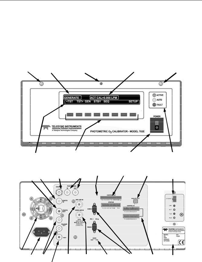
TELEDYNE API |
|
Getting Started |
M703E Calibrator Operator’s Manual |
VENTILATION CLEARANCE: Whether the calibrator is set up on a bench or installed into an instrument rack, be sure to leave sufficient ventilation clearance.
AREA |
MINIMUM REQUIRED CLEARANCE |
Back of the instrument |
10 cm / 4 inches |
Sides of the instrument |
2.5 cm / 1 inch |
Above and below the instrument. |
2.5 cm / 1 inch |
|
|
Various rack mount kits are available for this calibrator. See Chapter 5 of this manual for more information.
3.1.1. MODEL 703E CALIBRATOR
FASTENER |
MODE FIELD |
LOCKING SCREW |
MESSAGE FIELD |
FASTENER |
KEY DEFINITION |
|
|
KEYBOARD |
|
|
|
ON / OFF SWITCH |
STATUS LED’s |
||
|
|
Figure 3-1: |
M703E Front Panel Layout |
|
||||||
O3 Outlet to |
Photometer |
O3 Generator |
Photometer Gas Status Outputs Control Outputs Analog Output |
Optional Ethernet |
||||||
Photometer |
O3 Inlet |
Exhaust |
Connectors |
|
|
|
|
Card |
||
|
|
|
|
|
|
|
|
|
|
|
|
|
|
|
|
|
|
|
|
|
|
|
|
|
|
|
|
|
|
|
|
|
|
|
|
|
|
|
|
|
|
|
|
|
|
|
|
|
|
|
|
|
|
|
|
|
|
|
|
|
|
|
|
|
|
FAN |
|
|
|
|
AC Power |
Cal Gas |
Inlet for |
Inlet for External |
DCE-DTE COMM Ports Control Inputs Serial No. Tag |
Connector |
Outlets |
Dry Air |
Zero Air Source |
Switch |
Figure 3-2: M703E Rear Panel Layout
10 |
05744 Rev B |

|
TELEDYNE API |
M703E Calibrator Operator’s Manual |
Getting Started |
Ethernet PCA |
Gas Inlets & Outlets |
installed here |
|
(Optional) |
Photometer |
|
|
|
Pump |
Motherboard |
|
CPU PCA |
|
O3 Generator &
Photometer,
Pressure/Flow
Sensor PCA
O3 Generator
Assembly
Photometer
M/R Valve
O3 Generator
Lamp Driver
PHOTOMETER
5 LPM
Flow Control
Assy.
Pressure
Regulator
Inlet
Pressure
Regulator
Inlet
O3 Generator
Dry Air
Pump Inlet
Outlet to O3
Generator
DFU Filters
Charcoal
Scrubber on
Top
Figure 3-3: M703E Internal Layout – Top View
AC Power
Connector
Back Panel
Relay PCA
DC Power supplies
Dry Air
Pump
 Outlet
Dry Air
Pump
 Check
Check
Valve
1 LPM Flow
Control Assy.
Inlet to Regulator
ON / OFF  Switch
Front Panel
05744 Rev B |
11 |

TELEDYNE API |
|
Getting Started |
M703E Calibrator Operator’s Manual |
|
|
|
|
|
|
|
O |
|
|
|
|
|
|
|
3 |
CHARCOAL SCRUBBER |
|
|
|
|
O |
O |
FLOW SENSOR |
|
|
|
|
3 |
|||
Control Flow LPM) 0.2 to 0.(1 |
Control Flow lpm) 0.(5 |
cm(100 |
Flow |
3 GENERATOR |
Assembly Generator |
||
|
|
|
3 |
Control |
|
|
|
|
|
|
/min) |
|
|
|
|
|
|
Figure 3-4: |
|
M703E Pneumatic Diagram |
|||
12 |
05744 Rev B |
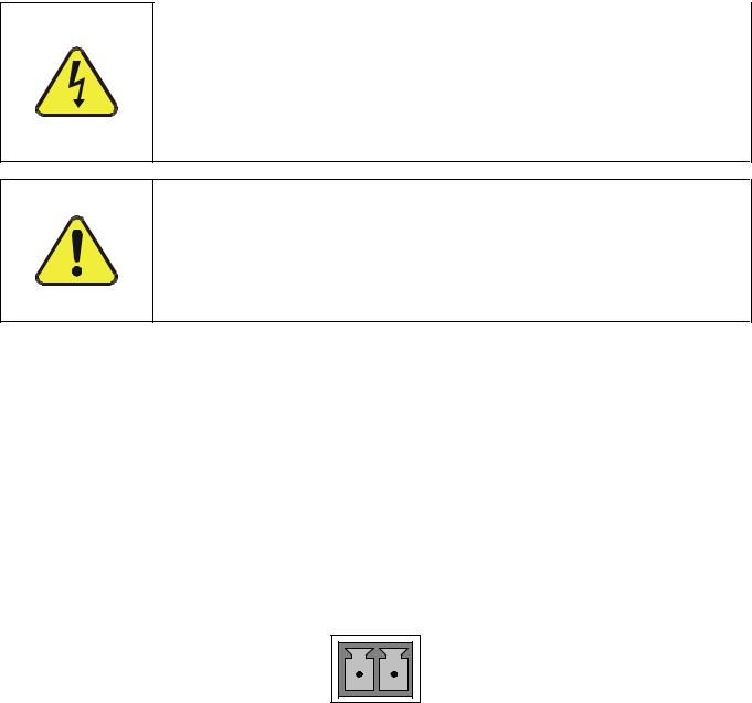
|
TELEDYNE API |
M703E Calibrator Operator’s Manual |
Getting Started |
3.2. ELECTRICAL CONNECTIONS
3.2.1. POWER CONNECTION
Verify the correct line voltage and frequency configuration on the serial number tag on the rear panel of the M703E.
Attach the power cord to the calibrator and plug it into a power outlet capable of carrying at least 10 A current at your AC voltage and that it is equipped with a functioning earth ground.
CAUTION
HIGH VOLTAGES ARE PRESENT INSIDE THE CALIBRATORS CASE
POWER CONNECTION MUST HAVE FUNCTIONING GROUND CONNECTION.
DO NOT DEFEAT THE GROUND WIRE ON POWER PLUG.
TURN OFF CALIBRATOR POWER BEFORE DISCONNECTING OR
CONNECTING ELECTRICAL SUBASSEMBLIES.
CAUTION
DO NOT LOOK AT THE PHOTOMETER UV LAMP.
UV LIGHT CAN CAUSE EYE DAMAGE.
ALWAYS WEAR GLASSES MADE FROM SAFETY UV FILTERING GLASS
(PLASTIC GLASSES WILL NOT DO).
3.2.2. ANALOG OUTPUT TEST CHANNEL CONNECTIONS
The M703E is equipped with an analog output channel accessible through a connector on the back panel of the instrument. The standard configuration for this output is 0-5 VDC. It can be set by the user to output one of a variety of diagnostic test functions (see Section 6.9.)
To access these signals attach a strip chart recorder and/or data-logger to the appropriate analog output connections on the rear panel of the calibrator.
Pin-outs for the analog output connector at the rear panel of the instrument are:
ANALOG OUT
+ –
Figure 3-5: M703E the TEST CHANNEL Connector
05744 Rev B |
13 |

TELEDYNE API |
|
Getting Started |
M703E Calibrator Operator’s Manual |
3.2.3. CONNECTING THE STATUS OUTPUTS
The status outputs report calibrator conditions via optically isolated NPN transistors, which sink up to 50 mA of DC current. These outputs can be used interface with devices that accept logic-level digital inputs, such as programmable logic controllers (PLC’s). Each Status bit is an open collector output that can withstand up to 40 VDC. All of the emitters of these transistors are tied together and available at D.
NOTE
Most PLC’s have internal provisions for limiting the current that the input will draw from an external device. When connecting to a unit that does not have this feature, an external dropping resistor must be used to limit the current through the transistor output to less than 50 mA. At 50 mA, the transistor will drop approximately 1.2V from its collector to emitter.
The status outputs are accessed via a 12-pin connector on the calibrator’s rear panel labeled STATUS. The function of each pin is defined in Table 3-1.
STATUS
|
|
|
|
|
|
|
|
|
|
|
|
|
|
|
|
|
|
|
|
|
|
|
|
|
|
|
|
|
|
|
|
|
|
|
|
|
|
|
|
|
|
|
|
|
|
1 |
2 |
3 |
4 |
5 |
6 |
|
7 |
8 |
D |
+ |
|
|
|
|
|
|
|
|
||||||||||
|
|
|
|
|
||||||||||
|
SYSTEM OK |
POWER OK |
CAL ACTIVE |
DIAG |
TEMP ALARM |
PRESS ALARM |
Unassigned |
Unassigned |
|
EMITTER BUSS |
+ 5 VDC |
CALIBRATOR INRTERNAL GROUND |
||
Figure 3-6: Status Output Connector
The pin assignments for the Status Outputs are:
Table 3-1: Status Output Pin Assignments
OUTPUT |
STATUS |
CONDITION |
|
# |
DEFINITION |
||
|
1SYSTEM OK On, if no faults are present.
2Unassigned 
3CAL ACTIVE On if the calibrator is in GENERATE mode
4 |
DIAG |
On if the calibrator is in DIAGNOSTIC mode |
5TEMP ALARM On whenever a temperature alarm is active.
6PRESS ALARM On whenever gas pressure alarm is active
7 & 8 |
Unassigned |
|
|
D |
Emitter BUSS |
The emitters of the transistors on pins 1 to 8 are bussed together. |
|
|
|
Digital Ground |
The ground level from the calibrator’s internal DC power supplies. |
|
|
||
|
|
||
|
|
|
|
D |
Emitter BUSS |
The emitters of the transistors on pins 9 to 16 are bussed together. |
|
+ |
DC POWER |
+ 5 VDC |
|
14 |
05744 Rev B |
Loading...