


Intel® Server Board SE7230NH1-E and
Intel® Server Platform SR1475NH1-E
User’s Guide
Intel Order Number D23185-004
Disclaimer
Information in this document is provided in connection with Intel® products. No license, express or implied, by estoppel or otherwise, to any intellectual property rights is granted by this document. Except as provided in Intel's Terms and Conditions of Sale for such products, Intel assumes no liability whatsoever, and Intel disclaims any express or implied warranty, relating to sale and/or use of Intel products including liability or warranties relating to fitness for a particular purpose, merchantability, or infringement of any patent, copyright or other intellectual property right. Intel products are not designed, intended or authorized for use in any medical, life saving, or life sustaining applications or for any other application in which the failure of the Intel product could create a situation where personal injury or death may occur. Intel may make changes to specifications and product descriptions at any time, without notice.
Intel server boards contain a number of high-density VLSI and power delivery components that need adequate airflow for cooling. Intel's own chassis are designed and tested to meet the intended thermal requirements of these components when the fully integrated system is used together. It is the responsibility of the system integrator that chooses not to use Intel developed server building blocks to consult vendor datasheets and operating parameters to determine the amount of airflow required for their specific application and environmental conditions. Intel Corporation can not be held responsible if components fail or the server board does not operate correctly when used outside any of their published operating or non-operating limits.
Intel, Intel Pentium, and Intel Xeon are trademarks or registered trademarks of Intel Corporation or its subsidiaries in
the United States and other countries.
* Other names and brands may be claimed as the property of others.
Copyright © 2005-2006, Intel Corporation. All Rights Reserved
ii |
Intel® Server Board SE7230NH1-E and Intel® Server Platform SR1475NH1-E User’s Guide |

Preface
About this Manual
Thank you for purchasing and using the Intel® Server Board SE7230NH1-E.
This manual is written for system technicians who are responsible for troubleshooting, upgrading, and repairing this server board. This document provides a brief overview of the features of the board/chassis, a list of accessories or other components you may need, troubleshooting information, and instructions on how to add and replace components on the Intel Server Board SE7230NH1-E User Guide. For the latest version of this manual, refer to http://support.intel.com/support/motherboards/server/SE7230NH1-E/.
Manual Organization
Chapter 1 provides a brief overview of the Server Board SE7230NH1-E. In this chapter, you will find a list of the server board features, drawings of the product, and product diagrams to help you identify components and their locations.
Chapter 2 provides instructions on using the utilities that are shipped with the board or that may be required to update the system. This includes how to navigate through the BIOS Setup screens, how to perform a BIOS update, and how to reset the password or CMOS. Information about the specific BIOS settings and screens is available in the Technical Product Specification. See "Additional Information and Software" for a link to the Technical Product Specification.
Chapter 3 provides instructions on adding and replacing components. Use this chapter for step-by-step instructions and diagrams for installing or replacing components such as the memory, processor, control panel board, and the battery, among other components.
Chapter 4 provides troubleshooting information. In this chapter, you will find BIOS error messages and POST code messages. You will also find suggestions for performing troubleshooting activities to identify the source of a problem.
Intel® Server Board SE7230NH1-E and Intel® Server Platform SR1475NH1-E User’s Guide |
iii |
Product Accessories
This server board is compatible with the following Intel® Server Chassis:
•Intel® Server Chassis SR1475
•Intel® Server Platform SR1475NH1-E
You may need or want to purchase one or more of the following accessory items for your server:
Processor, memory DIMMs, hard drive, floppy drive, CD-ROM or DVD-ROM drive, RAID controller, operating system.
For information about which accessories, memory, processors, and third-party hardware have been tested and can be used with your board, and for ordering information for Intel products, see http://support.intel.com/support/motherboards/server/SE7230NH1-E/ compat.htm.
Additional Information and Software
If you need more information about this product or information about the accessories that can be used with this server board, use the following resources. These files are available at http://support.intel.com/support/motherboards/server/SE7230NH1-E/
Unless otherwise indicated in the table below, once on this Web page, type the document or software name in the search field at the left side of the screen and select the option to search "SE7230NH1-E”.
For this information or software |
Use this Document or Software |
|
|
For in-depth technical information about this |
Intel® Server Board SE7230NH1-E Technical |
product, including BIOS settings and chipset |
Product Specification |
information |
|
|
|
If you just received this product and need to |
Intel® Server Board SE7230NH1-E Quick |
install it |
Start User's Guide in the product box |
|
|
For virtual system tours and interactive repair |
A link to the SMaRT Tool is available under |
information |
"Other Resources" at the right side of the |
|
screen at http://support.intel.com/support/ |
|
motherboards/server/SE7230NH1-E |
|
|
Accessories or other Intel server products |
Spares and Configuration Guide |
|
|
Hardware (peripheral boards, adapter cards) and |
Tested HardwareOperating Systems List |
operating systems that have been tested with this |
|
product |
|
|
|
Chassis that have been tested with this product |
Reference Chassis List |
|
|
Processors that have been tested with this |
Supported Processors |
product |
|
|
|
DIMMs that have been tested with this product |
Tested Memory List |
|
|
To make sure your system falls within the allowed |
Power Budget Tool |
power budget |
|
|
|
iv |
Intel® Server Board SE7230NH1-E and Intel® Server Platform SR1475NH1-E User’s Guide |
For software to manage your Intel® server |
Intel Server Management Software |
|
|
For drivers |
Driver (for an extensive list of drivers |
|
available) |
|
Operating System Driver (for operating |
|
system drivers) |
|
|
For firmware and BIOS updates, or BIOS |
Firmware Updates |
recovery |
|
|
|
For diagnostics test software |
Diagnostics |
|
See also the Intel® Server Deployment |
|
Toolkit CD that came with your server board |
|
|
Intel® Server Board SE7230NH1-E and Intel® Server Platform SR1475NH1-E User’s Guide |
v |
vi |
Intel® Server Board SE7230NH1-E and Intel® Server Platform SR1475NH1-E User’s Guide |

Safety Information
Important Safety Instructions
Read all caution and safety statements in this document before performing any of the instructions. See also Intel Server Boards and Server Chassis Safety Information on the Intel® Server Deployment Toolkit CD and/or at http://support.intel.com/support/ motherboards/server/sb/cs-010770.htm.
Wichtige Sicherheitshinweise
Lesen Sie zunächst sämtliche Warnund Sicherheitshinweise in diesem Dokument, bevor Sie eine der Anweisungen ausführen. Beachten Sie hierzu auch die Sicherheitshinweise zu Intel-Serverplatinen und Servergehäusen auf der Intel® Server Deployment Toolkit CD oder unter http://support.intel.com/support/motherboards/server/sb/cs-010770.htm.
Consignes de sécurité
Lisez attention toutes les consignes de sécurité et les mises en garde indiquées dans ce document avant de suivre toute instruction. Consultez Intel Server Boards and Server Chassis Safety Information sur le Intel® Server Deployment Toolkit CD ou bien rendezvous sur le site http://support.intel.com/support/motherboards/server/sb/cs-010770.htm.
Instrucciones de seguridad importantes
Lea todas las declaraciones de seguridad y precaución de este documento antes de realizar cualquiera de las instrucciones. Vea Intel Server Boards and Server Chassis Safety Information en el Intel® Server Deployment Toolkit CD y/o en http://support.intel.com/ support/motherboards/server/sb/cs-010770.htm.
/ http://support.intel.com/support/motherboards/server/safecert.htm Intel Server Boards and Server Chassis Safety Information Intel
Intel® Server Board SE7230NH1-E and Intel® Server Platform SR1475NH1-E User’s Guide |
vii |
Safety Information
Warnings
Heed safety instructions: Before working with your server product, whether you are using this guide or any other resource as a reference, pay close attention to the safety instructions. You must adhere to the assembly instructions in this guide to ensure and maintain compliance with existing product certifications and approvals. Use only the described, regulated components specified in this guide. Use of other products / components will void the UL listing and other regulatory approvals of the product and will most likely result in noncompliance with product regulations in the region(s) in which the product is sold.
System power on/off: The power button DOES NOT turn off the system AC power. To remove power from system, you must unplug the AC power cord from the wall outlet. Make sure the AC power cord is unplugged before you open the chassis, add, or remove any components.
Hazardous conditions, devices and cables: Hazardous electrical conditions may be present on power, telephone, and communication cables. Turn off the server and disconnect the power cord, telecommunications systems, networks, and modems attached to the server before opening it. Otherwise, personal injury or equipment damage can result.
Electrostatic discharge (ESD) and ESD protection: ESD can damage disk drives, boards, and other parts. We recommend that you perform all procedures in this chapter only at an ESD workstation. If one is not available, provide some ESD protection by wearing an antistatic wrist strap attached to chassis ground any unpainted metal surface on your server when handling parts.
ESD and handling boards: Always handle boards carefully. They can be extremely sensitive to ESD. Hold boards only by their edges. After removing a board from its protective wrapper or from the server, place the board component side up on a grounded, static free surface. Use a conductive foam pad if available but not the board wrapper. Do not slide board over any surface.
Installing or removing jumpers: A jumper is a small plastic encased conductor that slips over two jumper pins. Some jumpers have a small tab on top that you can grip with your fingertips or with a pair of fine needle nosed pliers. If your jumpers do not have such a tab, take care when using needle nosed pliers to remove or install a jumper; grip the narrow sides of the jumper with the pliers, never the wide sides. Gripping the wide sides can damage the contacts inside the jumper, causing intermittent problems with the function controlled by that jumper. Take care to grip with, but not squeeze, the pliers or other tool you use to remove a jumper, or you may bend or break the pins on the board.
viii |
Intel® Server Board SE7230NH1-E and Intel® Server Platform SR1475NH1-E User’s Guide |

Contents
About this Manual ................................................................................................................. |
iii |
Manual Organization ............................................................................................................. |
iii |
Product Accessories ............................................................................................................. |
iv |
Additional Information and Software ..................................................................................... |
iv |
Important Safety Instructions ............................................................................................... |
vii |
Wichtige Sicherheitshinweise .............................................................................................. |
vii |
Consignes de sécurité ......................................................................................................... |
vii |
Instrucciones de seguridad importantes .............................................................................. |
vii |
Warnings.............................................................................................................................. |
viii |
Server Board Features ............................................................................................... |
1 |
Connector and Header Locations .......................................................................................... |
4 |
Configuration Jumpers ........................................................................................................... |
5 |
Back Panel Connectors ......................................................................................................... |
6 |
Hardware Requirements ........................................................................................................ |
7 |
Processor .................................................................................................................................... |
7 |
Memory ....................................................................................................................................... |
7 |
Power Supply .............................................................................................................................. |
8 |
Optional Hardware ................................................................................................................. |
8 |
Hard Disk Drives ......................................................................................................................... |
8 |
Server Utilities ............................................................................................................ |
9 |
Using the BIOS Setup Utility .................................................................................................. |
9 |
Starting Setup ............................................................................................................................. |
9 |
If You Cannot Access Setup ....................................................................................................... |
9 |
Setup Menus ............................................................................................................................... |
9 |
Upgrading the BIOS ............................................................................................................. |
11 |
Preparing for the Upgrade ........................................................................................................ |
11 |
Upgrading the BIOS .................................................................................................................. |
12 |
Clearing the CMOS .............................................................................................................. |
12 |
Hardware Installations and Upgrades .................................................................... |
13 |
Before You Begin ................................................................................................................. |
13 |
Tools and Supplies Needed ...................................................................................................... |
13 |
Installing and Removing Memory ........................................................................................ |
13 |
Installing DIMMs ....................................................................................................................... |
14 |
Removing DIMMs ..................................................................................................................... |
15 |
Installing or Replacing the Processor .................................................................................. |
15 |
Installing the Processor ............................................................................................................ |
15 |
Installing the Active Heat Sink .................................................................................................. |
18 |
Installing the Passive Heat Sink ............................................................................................... |
19 |
Intel® Server Board SE7230NH1-E and Intel® Server Platform SR1475NH1-E User’s Guide |
ix |
Removing a Processor ............................................................................................................. |
20 |
Replacing the Backup Battery ............................................................................................. |
21 |
Troubleshooting ........................................................................................................ |
23 |
Resetting the System .......................................................................................................... |
23 |
Problems following Initial System Installation ...................................................................... |
23 |
Hardware Diagnostic Testing .............................................................................................. |
24 |
Verifying Proper Operation of Key System Lights .................................................................... |
25 |
Confirming Loading of the Operating System ........................................................................... |
25 |
Specific Problems and Corrective Actions .......................................................................... |
25 |
Power Light Does Not Light ...................................................................................................... |
26 |
No Characters Appear on Screen ............................................................................................ |
26 |
Characters Are Distorted or Incorrect ....................................................................................... |
27 |
System Cooling Fans Do Not Rotate Properly ......................................................................... |
27 |
Diskette Drive Activity Light Does Not Light ............................................................................. |
28 |
CD-ROM Drive or DVD-ROM Drive Activity Light Does Not Light ............................................ |
28 |
Cannot Connect to a Server ..................................................................................................... |
28 |
Problems with Network ............................................................................................................. |
29 |
Devices are not Recognized under Device Manager .............................................................. |
31 |
LED Information ........................................................................................................................ |
31 |
BIOS POST Beep Codes ......................................................................................................... |
32 |
A Getting Help .......................................................................................................... |
33 |
World Wide Web ................................................................................................................. |
33 |
Telephone ........................................................................................................................... |
33 |
B Safety Information ................................................................................................ |
37 |
English ................................................................................................................................. |
37 |
Server Safety Information ......................................................................................................... |
37 |
Safety Warnings and Cautions ................................................................................................. |
37 |
Intended Application Uses ........................................................................................................ |
38 |
Site Selection ............................................................................................................................ |
38 |
Equipment Handling Practices ................................................................................................. |
38 |
Power and Electrical Warnings ................................................................................................. |
38 |
System Access Warnings ......................................................................................................... |
39 |
Rack Mount Warnings .............................................................................................................. |
40 |
Electrostatic Discharge (ESD) .................................................................................................. |
40 |
Other Hazards .......................................................................................................................... |
41 |
Sicherheitshinweise für den Server .......................................................................................... |
42 |
Sicherheitshinweise und Vorsichtsmaßnahmen ....................................................................... |
42 |
Zielbenutzer der Anwendung .................................................................................................... |
43 |
Standortauswahl ....................................................................................................................... |
43 |
Handhabung von Geräten ........................................................................................................ |
43 |
Warnhinweise für den Systemzugang ...................................................................................... |
45 |
Elektrostatische Entladungen (ESD) ........................................................................................ |
46 |
Andere Gefahren ...................................................................................................................... |
47 |
Français ............................................................................................................................... |
48 |
x |
Intel® Server Board SE7230NH1-E and Intel® Server Platform SR1475NH1-E User’s Guide |
Consignes de sécurité sur le serveur ....................................................................................... |
48 |
Sécurité: avertissements et mises en garde ............................................................................. |
48 |
Domaines d’utilisation prévus ................................................................................................... |
49 |
Sélection d’un emplacement ..................................................................................................... |
49 |
Pratiques de manipulation de l’équipement .............................................................................. |
49 |
Décharges électrostatiques†(ESD) .......................................................................................... |
52 |
Autres risques ........................................................................................................................... |
53 |
Información de seguridad del servidor ...................................................................................... |
54 |
Advertencias y precauciones sobre seguridad ......................................................................... |
54 |
Aplicaciones y usos previstos ................................................................................................... |
55 |
Selección de la ubicación ......................................................................................................... |
55 |
Manipulación del equipo ........................................................................................................... |
55 |
Advertencias el acceso al sistema ............................................................................................ |
57 |
Descarga electrostática (ESD) ................................................................................................. |
58 |
C Regulatory and Compliance Information ........................................................... |
65 |
Product Regulatory Compliance .......................................................................................... |
65 |
Product Safety Compliance ...................................................................................................... |
65 |
Product EMC Compliance - Class A Compliance ..................................................................... |
65 |
Certifications / Registrations / Declarations .............................................................................. |
66 |
Product Regulatory Compliance Markings ............................................................................... |
66 |
Electromagnetic Compatibility Notices ................................................................................ |
67 |
FCC (USA) ................................................................................................................................ |
67 |
Industry Canada (ICES-003) .................................................................................................... |
68 |
Europe (CE Declaration of Conformity) .................................................................................... |
68 |
Taiwan Declaration of Conformity (BSMI) ................................................................................ |
68 |
Korean Compliance (RRL) ........................................................................................................ |
69 |
D Intel® Server Issue Report Form ........................................................................ |
71 |
Intel® Server Board SE7230NH1-E and Intel® Server Platform SR1475NH1-E User’s Guide |
xi |
xii |
Intel® Server Board SE7230NH1-E and Intel® Server Platform SR1475NH1-E User’s Guide |

List of Figures
Figure 1. Intel® Server Board SE7230NH1-E............................................................................. |
1 |
||
Figure 2. Server Board Connector and Component Locations .................................................. |
4 |
||
Figure 3. DDR vs. DDR2 DIMMs.............................................................................................. |
13 |
||
Figure 4. Installing DIMMs........................................................................................................ |
14 |
||
Figure 5. Lift Processor Socket Lever ...................................................................................... |
16 |
||
Figure 6. |
Lift Processor Load Plate .......................................................................................... |
16 |
|
Figure 7. |
Removing Protective Processor Cover ..................................................................... |
17 |
|
Figure 8. |
Installing the Processor............................................................................................. |
17 |
|
Figure 9. |
Removing the Socket Protective Cover .................................................................... |
17 |
|
Figure 10. |
Closing the Load Plate and Socket Lever ............................................................... |
18 |
|
Figure 11. |
Installing the Active Heat Sink................................................................................. |
19 |
|
Figure 12. |
Installing the Passive Heat Sink.............................................................................. |
20 |
|
Figure 13. |
Removing the Battery.............................................................................................. |
22 |
|
Intel® Server Board SE7230NH1-E and Intel® Server Platform SR1475NH1-E User’s Guide |
xiii |
xiv |
Intel® Server Board SE7230NH1-E and Intel® Server Platform SR1475NH1-E User’s Guide |

List of Tables
Table 1. |
Server Board Features ................................................................................................ |
2 |
Table 2. Configuration Jumpers ................................................................................................. |
5 |
|
Table 3. LED Information ........................................................................................................... |
6 |
|
Table 4. Keyboard Commands................................................................................................. |
10 |
|
Table 5. |
LED Information ......................................................................................................... |
31 |
Table 6. |
POST Error Beep Codes............................................................................................ |
32 |
Table 7. |
Product Certification Markings ................................................................................... |
66 |
Intel® Server Board SE7230NH1-E and Intel® Server Platform SR1475NH1-E User’s Guide |
xv |
xvi |
Intel® Server Board SE7230NH1-E and Intel® Server Platform SR1475NH1-E User’s Guide |

1 Server Board Features
This chapter briefly describes the main features of the Intel® Server Board SE7230NH1- E. This chapter provides drawings of the product, a list of the server board features, and diagrams showing the location of important components and connections on the server board.
|
|
|
Sys Fan 1 |
12V CPU Power |
|
|
B |
C |
D |
||
A |
E |
||||
|
|||||
CPU Fan |
|
|
|
||
Intrusion |
Sys Fan 2 |
|
|||
|
|
||||
|
|
|
|
||
P
Main Power |
CPU |
|
Socket
O |
|
|
|
Serial ATA |
|
|
|
N |
|
|
|
Front Panel |
|
|
|
M |
|
|
|
5 |
6 |
7 |
8 |
SCSI LED |
|
|
|
Serial ATA |
|
J |
I |
|
|
|
I |
|
|
|
|
L |
|
H |
G |
F |
|
D |
Floppy |
||||
|
E |
|
|
Sys Fan 4 |
Sys Fans |
|
K |
|
Sys Fan 3 |
||
|
|
|
|
||
|
|
|
|
|
TP01795 |
Figure 1. Intel® Server Board SE7230NH1-E
Intel® Server Board SE7230NH1-E and Intel® Server Platform SR1475NH1-E User’s Guide |
1 |
Table 1 summarizes the features of the server board.
Table 1. Server Board Features
Feature |
Description |
|
|
Processor |
• Support for one Intel® Pentium® D, Pentium® 4 or Celeron® D |
|
processor in the LGA775 package |
|
• Capable of 1066 MT/s on system bus when using the Intel® |
|
Pentium® 4 Processor Extreme Edition supporting Hyper- |
|
Threading Technology |
|
• Supports Intel® Dual Core Architecture |
|
• Supports Intel® Hyper-Threading Technology |
|
• Supports Intel® Extended Memory System 64 Technology |
|
(EM64T) |
|
|
Memory |
• 4 DIMM sockets supporting 400/533/667MHz DDR2 DIMMs |
|
• Data bandwidth per channel of 4.2GB/s or 8.4GB/s in dual |
|
channel when using DDR2 667MHz |
|
• Support for up to two DDR2 channels for a total of 4 DIMMs (2 |
|
DIMMs / Channel) providing up to 8GB max memory capacity |
|
|
Intel® E7230 Chipset |
• Intel® E7230 MCH Memory Controller Hub |
Components |
• Intel® ICH7R I/O controller |
|
• Intel® 6702 PXH-V-V PCI-X Hub (LX SKU only) |
|
• 12-deep In-Order Queue |
|
|
I/O Control |
LC Super I/O = SMsC* LP47M182NR |
|
LX Super I/O = National Semiconductor* PC8374LOIBU |
|
External connections: |
|
• Stacked PS2 Keyboard/Mouse connections |
|
• RJ45 Serial B port |
|
• Two RJ45 NIC connectors for 10/100/1000 Mb connections |
|
• Two USB 2.0 ports |
|
Internal connections: |
|
• One USB port header which supports two USB 2.0 ports |
|
• One DH10 Serial A header |
|
• Two SATA-150 connectors with integrated RAID 0/1 support |
|
• One ATA-100 connector |
|
• SSI-compliant 34-pin control panel header |
|
|
Video |
Integrated stand-alone ATI ES1000 graphics engine that supports |
|
standard SVGA drivers with analog display capabilities. The graphics |
|
subsystem has 16 MB of dedicated memory to support the onboard |
|
video controller |
|
|
2 |
Intel® Server Board SE7230NH1-E and Intel® Server Platform SR1475NH1-E User’s Guide |
Table 1. Server Board Features
Feature |
Description |
|
|
LX Board I/O Subsystem |
Five independent PCI Buses: |
|
• Segment A - Two PCI 32-bit/33-MHz 3.3V Universal connectors |
|
supporting full length PCI add-in cards (Adapters which support |
|
5V only are not supported) and one embedded Intel® 10/100/ |
|
1000 82541PI gigabit Ethernet Controller (Supports PCI |
|
Specification, Rev 2.3) |
|
• Segment B - One x1 PCI Express resource implemented as a |
|
single x4 PCI Express connector supporting x1/x2/x4 PCI |
|
Express add-in cards |
|
• Segment C - One x1 PCI Express resource implemented as an |
|
embedded Intel® 10/100/1000 82573E gigabit Ethernet |
|
Controller |
|
• Segment D - One x4 PCI Express resource supporting PXH-V-V |
|
PCI-X Hub. PXH-V-V supports one dedicated PCI-X 64/100MHz |
|
slot and PCI-X portion of the Intel Adaptive Slot |
|
• Segment E - One x8 PCI Express resource supporting PCI |
|
Express portion of Intel Adaptive Slot. Supports x1/x2/x4/x8 PCI |
|
Express add-in cards via riser card |
|
|
LC Board I/O Subsystem |
Five independent PCI Buses: |
|
• Segment A - Two PCI 32-bit/33-MHz 3.3V Universal connectors |
|
supporting full length PCI add-in cards (Adapters which support |
|
5V only are not supported) and one embedded Intel® 10/100/ |
|
1000 82541PI gigabit Ethernet Controller (Supports PCI |
|
Specification, Rev 2.3) |
|
• Segment B - One x1 PCI Express resource implemented as a |
|
single x4 PCI Express connector supporting x1/x2/x4 PCI |
|
Express add-in cards |
|
• Segment C - One x1 PCI Express resource implemented as an |
|
embedded Intel® 10/100/1000 82573E gigabit Ethernet |
|
Controller |
|
• Segment D - One x4 PCI Express resource implemented as a |
|
single x8 PCI Express connector supporting x1/x2/x4/x8 PCI |
|
Express add-in cards |
|
• Segment E - One x8 PCI Express resource implemented as a |
|
single x8 PCI Express connector supporting x1/x2/x4/x8 PCI |
|
Express add-in cards |
|
|
Hard drive |
• Ultra ATA100 support: One IDE channel capable of supporting |
|
up to two drives. |
|
• SATA support: Four independent SATA ports support data |
|
transfer rates up to 1.5 Gb/s (150MB/s) per port |
|
|
Fans |
• Two general purpose 3-pin fan headers |
|
• Two general purpose 4-pin fan headers |
|
• One 4-pin processor fan header (active heatsink required) |
|
• Four 8-pin dual rotor fan headers for Intel High Density |
|
applications (Intel Server Chassis SR1475 and Intel Server |
|
Platform SR1475NH1-E) |
|
|
Other |
Intel Light Guided Diagnostic LED’s to display POST code indicators |
|
during boot (LX version only) |
|
|
Intel® Server Board SE7230NH1-E and Intel® Server Platform SR1475NH1-E User’s Guide |
3 |
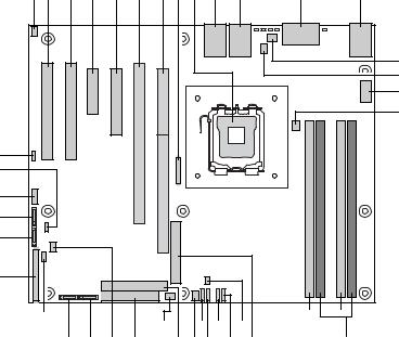
Connector and Header Locations
A B C D E F G H I J K L M
N
O
P
Q
MM
LL
KK
JJ
II
HH |
|
|
|
|
BB |
Y W |
U |
|
|
|
|
GG |
FF EE DD CC AA Z X V |
T |
|
S R |
||||||
|
|
|
|
|
|
|
|
|
|
TP01781 |
|
|
|
|
|
|
|||||
A. Intrusion Header |
|
N. SysFan1 |
|
|
AA.PATA IDE Connector |
|||||
|
|
|
|
|
||||||
B. PCI (32bit/33MHz) Slot 1 |
O. SysFan2 |
|
|
BB.SysFan3 |
||||||
|
|
|
||||||||
C. PCI (32bit/33MHz) Slot 2 |
P. 2x4 Processor Power |
CC.Floppy Connector |
||||||||
|
|
|
|
|||||||
D. PCI Express* x4 (x1 Lane) |
Q. Processor Fan |
|
DD.SCSI LED Connector |
|||||||
Slot 3 |
|
|
|
|
|
|
|
|
||
|
|
|
|
|||||||
E. PCI Express* x8 (x4 Lane) |
R. Memory Bank 2 |
|
EE.SATA Port 3 |
|||||||
Slot 4 |
|
|
|
|
|
|
|
|
||
|
|
|
|
|||||||
F. PCI-X (64bit/100MHz) Slot 5 - |
S. Memory Bank 1 |
|
FF.SATA Port 2 |
|||||||
LX version only |
|
|
|
|
|
|
|
|
||
|
|
|
|
|
||||||
G. PCI Express* x8 (x8 Lane) |
T. Main Power |
|
|
GG.Clear CMOS Jumper |
||||||
Slot 6 - LC version only; Riser |
|
|
|
|
|
|
|
|||
Card Slot - LX version only |
|
|
|
|
|
|
|
|
||
|
|
|
|
|||||||
H. Battery |
|
U. Hardware Management |
HH.Front Panel Connector |
|||||||
|
|
|
|
Controller |
|
|
|
|
|
|
|
|
|
|
|||||||
I. Processor Socket |
|
V. SysFan8 - LX version only |
II. SATA Port 1 |
|||||||
|
|
|
|
|||||||
J. NIC1 and USB1-2 |
|
W. SysFan7 - LX version only |
JJ.SATA Port 0 |
|||||||
|
|
|
|
|||||||
K. NIC2 |
|
X. SysFan6 - LX version only |
KK.External USB Connector |
|||||||
|
|
|
|
|||||||
L. Serial A and Video Port |
|
Y. SysFan5 - LX version only |
LL.CMOS Config Jumper |
|||||||
|
|
|
|
|
||||||
M. PS2 Stacked Mouse/Keyboard |
Z. SysFan4 |
|
|
MM.HSBP Connector |
||||||
|
|
|
|
|
|
|
|
|
|
|
Figure 2. Server Board Connector and Component Locations
4 |
Intel® Server Board SE7230NH1-E and Intel® Server Platform SR1475NH1-E User’s Guide |
Configuration Jumpers |
|||
CMOS Configuration |
|||
|
Jumper (J9H3) |
||
A |
3 |
Config |
|
|
2 |
Normal |
|
|
|
||
|
Off - Recovery |
||
|
Clear CMOS |
||
|
Jumper (J9G3) |
||
B |
3 |
Clear |
|
2 |
|||
|
Normal |
||
|
|
||
|
|
TP01794 |
|
Table 2. Configuration Jumpers
Jumper Name |
What happens at system reset... |
|
|
CMOS Configuration |
Pins 1-2 should be jumpered for normal system operation. |
|
If pins 2-3 are jumpered, the system will enter a configuration menu |
|
that is only available by jumpering these pins. These pins should not |
|
be jumpered for normal operation. |
|
If the jumper is removed, the system will attempt to recover the BIOS |
|
by loading the BIOS code into the flash device from a floppy disk. |
|
This is typically used when the BIOS has become corrupted. The |
|
jumper should not be removed for normal operation. |
|
|
Clear CMOS |
Pins 1-2 should be jumpered for normal system operation. |
|
If pins 2-3 are jumpered, the CMOS settings will be cleared on the |
|
next reset. These pins should not be jumpered for normal operation. |
|
|
Intel® Server Board SE7230NH1-E and Intel® Server Platform SR1475NH1-E User’s Guide |
5 |
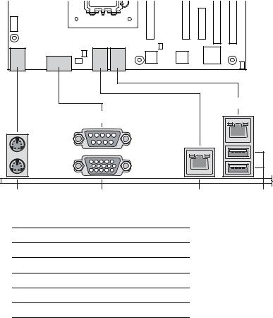
Back Panel Connectors
E
B
A C D F
TP01783
A.Stacked PS2 Mouse/Keyboard Ports
B.Serial A
C.Video
D.NIC2 (10/100/1000Mb)
E.NIC1 (10/100/1000Mb)
F.USB1-2
The NIC LEDs at the right and left of each NIC provide the following information.
Table 3. LED Information
LED |
LED State |
Description |
|
|
|
Left |
Off |
No network connection |
|
|
|
|
Solid Amber |
Network connection in place |
|
|
|
|
Blinking Amber |
Transmit/receive activity |
|
|
|
Right |
Off |
10 Mbps connection (if left LED is on or blinking) |
|
|
|
|
Solid Amber |
100 Mbps connection |
|
|
|
|
Solid Green |
1000 Mbps connection |
|
|
|
6 |
Intel® Server Board SE7230NH1-E and Intel® Server Platform SR1475NH1-E User’s Guide |
Hardware Requirements
To avoid integration difficulties and possible board damage, your system must meet the requirements outlined below. For a list of qualified components, see the links under "Additional Information and Software."
Processor
One Intel® Pentium® 4 processor, Pentium® D processor, Celeron® D processor, or Pentium® processor Extreme Edition. For a complete list of supported processors, see the links under "Additional Information and Software."
Memory
The Server Board SE7230NH1-E provides four DIMM sockets across two channels, Channel A and Channel B. Channel A consists of DIMM sockets 1A and 2A. Channel B consists of DIMM sockets 1B and 2B.
A minimum of one 256MB DIMM is required in DIMM socket 1A. This uses singlechannel interleave. However, for dual-channel interleave, providing optimum performance, a minimum of two DIMMs should be installed in DIMM sockets 1A and 1B. Except for the option of installing a single DIMM in socket 1A or 1B, DIMMs must be installed in pairs and populated as follows:
•DIMM1A and DIMM 1B: Populate these two sockets together first.
•DIMM 2A and DIMM 2B: Populate these sockets in addition to DIMM 1A and DIMM 1B if four DIMMs are to be used.
DIMMs must meet the following requirements:
•DDR2 400/533/667 , un-buffered, DDR2 DIMM modules
•DIMM organization: x72 ECC or x 64 Non-ECC
•Pin count: 240
•DIMM capacity: 256 MB, 512 MB, 1 GB and 2 GB DIMMs
•Serial PD: JEDEC Rev 2.0
•Serial PD: JEDEC Rev 2.0
•Interface: SSTL2
For a complete list of supported memory DIMMs, see the links under "Additional Information and Software."
In order to operate in Dual Channel Dynamic Paging Mode, the following conditions must be met:
•Two identical DIMMs are installed, one each in DIMM_1A and DIMM_1B
•Four identical DIMMs are installed (one in each socket location)
Intel® Server Board SE7230NH1-E and Intel® Server Platform SR1475NH1-E User’s Guide |
7 |
Installing only 3 DIMMs is not supported. Do not use DIMMs that are not “matched” (same type and speed). Use of identical memory parts is always the preferred method.See the Intel® Server Board SE7230NH1-E Technical Product Specification for additional information regarding the memory sub-system.
Power Supply
A minimum of 350 Watts is required. Your supply must provide a minimum of 1.2A of 5V standby current or the board will not boot.
Optional Hardware
Hard Disk Drives
The Server Board SE7230NH1-E supports up to four SATA devices.
See the documentation included with your server chassis for additional drive information and drive installation instructions.
8 |
Intel® Server Board SE7230NH1-E and Intel® Server Platform SR1475NH1-E User’s Guide |

2 Server Utilities
Using the BIOS Setup Utility
This section describes the BIOS Setup Utility options, which is used to change server configuration defaults. You can run BIOS Setup with or without an operating system being present. See “Additional Information and Software” for a link to the Technical Product Specification where you will find details about specific BIOS setup screens.
Starting Setup
You can enter and start BIOS Setup under several conditions:
•When you turn on the server, after POST completes the memory test
•When you have moved the CMOS jumper on the server board to the “Clear CMOS” position (enabled)
In the two conditions listed above, during the Power On Self Test (POST), you will see this prompt:
Press <F2> to enter SETUP
In a third condition, when CMOS/NVRAM has been corrupted, you will see other prompts but not the <F2> prompt:
Warning: CMOS checksum invalid
Warning: CMOS time and date not set
In this condition, the BIOS will load default values for CMOS and attempt to boot.
If You Cannot Access Setup
If you are not able to access BIOS Setup, you might need to clear the CMOS memory. For instructions on clearing the CMOS, see “Clearing the CMOS”.
Setup Menus
Each BIOS Setup menu page contains a number of features. Except for those features that are provided only to display automatically configured information, each feature is associated with a value field that contains user-selectable parameters. These parameters can be changed if the user has adequate security rights. If a value cannot be changed for any reason, the feature’s value field is inaccessible.
Table 4 describes the keyboard commands you can use in the BIOS Setup menus.
Intel® Server Board SE7230NH1-E and Intel® Server Platform SR1475NH1-E User’s Guide |
9 |
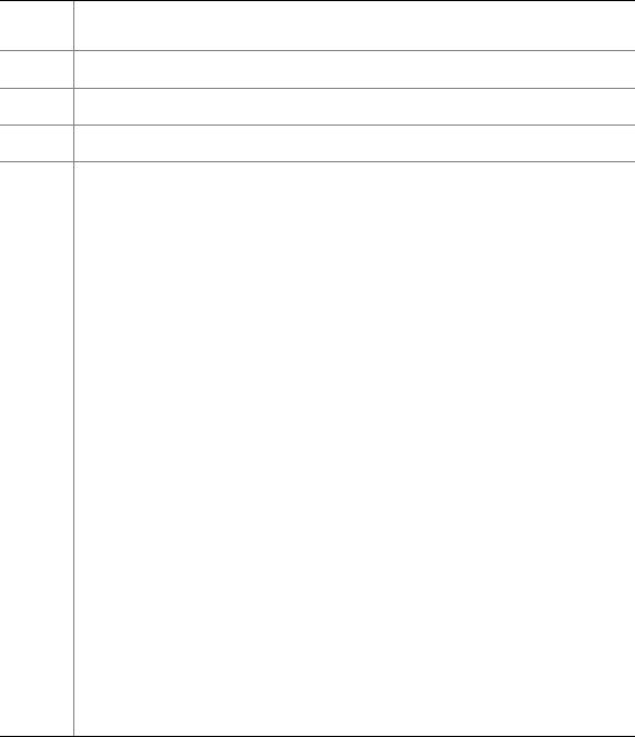
Table 4. Keyboard Commands
Press |
Description |
|
|
<F1> |
Help - Pressing F1 on any menu invokes the general Help window. |
←→ The left and right arrow keys are used to move between the major menu pages. The keys have no affect if a submenu or pick list is displayed.
¦Select Item up - The up arrow is used to select the previous value in a menu item’s option list, or a value field pick list. Pressing the Enter key activates the selected item.
ØSelect Item down - The down arrow is used to select the next value in a menu item’s option list, or a value field pick list. Pressing the Enter key activates the selected item.
F5/- |
Change Value - The minus key or the F5 function key is used to change the value of the |
|
current item to the previous value. This key scrolls through the values in the associated pick |
|
list without displaying the full list. |
|
|
F6/+ |
Change Value - The plus key or the F6 function key is used to change the value of the current |
|
menu item to the next value. This key scrolls through the values in the associated pick list |
|
without displaying the full list. On 106-key Japanese keyboards, the plus key has a different |
|
scan code than the plus key on the other keyboard, but it has the same effect. |
|
|
<Enter> |
Execute Command - The Enter key is used to activate submenus when the selected feature is |
|
a submenu, or to display a pick list if a selected feature has a value field, or to select a sub- |
|
field for multi-valued features like time and date. If a pick list is displayed, the Enter key will |
|
undo the pick list, and allow another selection in the parent menu. |
|
|
<Esc> |
Exit - The ESC key provides a mechanism for backing out of any field. This key will undo the |
|
pressing of the Enter key. When the ESC key is pressed while editing any field or selecting |
|
features of a menu, the parent menu is re-entered. When the ESC key is pressed in any |
|
submenu, the parent menu is re-entered. When the ESC key is pressed in any major menu, |
|
the exit confirmation window is displayed and the user is asked whether changes can be |
|
discarded. |
|
|
<F9> |
Setup Defaults - Pressing F9 causes the following to appear: |
|
Setup Confirmation |
|
Load default configuration now? |
|
[Yes] [No] |
|
If “Yes” is selected and the Enter key is pressed, all Setup fields are set to their default values. |
|
If “No” is selected and the Enter key is pressed, or if the ESC key is pressed, the user is |
|
returned to where they were before F9 was pressed without affecting any existing field values. |
|
|
<F10> |
Save and Exit - Pressing F10 causes the following message to appear: |
|
Setup Confirmation |
|
Save Configuration changes and exit now? |
|
[Yes] [NO] |
|
If “Yes” is selected and the Enter key is pressed, all changes are saved and Setup is exited. If |
|
“No” is selected and the Enter key is pressed, or the ESC key is pressed, the user is returned |
|
to where they were before F10 was pressed without affecting any existing values. |
10 |
Intel® Server Board SE7230NH1-E and Intel® Server Platform SR1475NH1-E User’s Guide |
Upgrading the BIOS
The upgrade utility allows you to upgrade the BIOS in flash memory. The code and data in the upgrade file include the following:
•On-board system BIOS, including the recovery code, BIOS Setup Utility, and strings.
•On-board video BIOS, SCSI BIOS, and other option ROMs for devices embedded on the server board.
•OEM binary area
•Microcode
•A way to change the BIOS language
Preparing for the Upgrade
The steps below explain how to prepare to upgrade the BIOS, including how to record the current BIOS settings and how to obtain the upgrade utility.
Note: In the unlikely event that a BIOS error occurs during the BIOS update process, a recovery process may need to be followed to return the system to service. See “Additional Information and Software” for a link to necessary software and instrutions.
Recording the Current BIOS Settings
1. Boot the computer and press <F2> when you see the message:
Press <F2> Key if you want to run SETUP
2. Write down the current settings in the BIOS Setup program.
Note: Do not skip step 2. You will need these settings to configure your computer at the end of the procedure.
Obtaining the Upgrade
Download the BIOS image file to a temporary folder on your hard drive. See “Additional Information and Software” for a link to the update software.
Note: Review the instructions and release notes that are provided in the readme file distributed with the BIOS image file before attempting a BIOS upgrade. The release notes contain critical information regarding jumper settings, specific fixes, or other information to complete the upgrade.
Intel® Server Board SE7230NH1-E and Intel® Server Platform SR1475NH1-E User’s Guide |
11 |
 Loading...