


C150-E192-01EN
fi-4990C Image Scanner
Operator's Guide
fi-4990C Image Scanner
Operator's Guide

Edition |
Date published |
Revised contents |
01 |
February, 2001 |
First edition |
|
|
|
|
Specification No. C150-E192-01EN |
|
This equipment has been tested and found to comply with the limits for a Class A digital device, pursuant to Part 15 of the FCC Rules. These limits are designed to provide reasonable protection against harmful interference when the equipment is operated in a commercial environment. This equipment generates, uses, and can radiate radio frequency energy and, if not installed and used in accordance with the instruction manual, may cause harmful interference to radio communications. Operation of this equipment in a residential area is likely to cause harmful interference in which case the user will be required to correct the interference at his own expense.
This digital apparatus does not exceed the Class A limit for radio noise emissions from digital apparatus set out in the Radio interference Regulations of the Canadian Department of Communications.
Le pésent appareil numérique n’ément pas de bruits radioélectriques dépassant les limites applicables aux appareils numériques de la classe A prescridtes dans le Réglesment sur le brouillage radioélectrique dicté par le ministere des Communications du Canada.
MaschinenlärmInformationsverordnung 3. GSGV, 18-01. 1991: Der arbeisplatzbezogene Schalldruckpegel beträgt 70 dB (A) oder weniger gemäß ISO7779.
The contents of this manual may be revised without prior notice.
All Rights Reserved, Copyright © 2001 FUJITSU LIMITED. Printed in Japan.
No part of this manual may be reproduced in any form without permission.
Please send your comments on this manual or on Fujitsu products to the following addresses:
North American contact: |
Asian contact: |
|
FUJITSU COMPUTER PRODUCTS OF |
FUJITSU HONG KONG LTD. |
|
AMERICA, INC. |
10/F, Lincoln House, 979 King’s Road, |
|
2904 Orchard Parkway, San Jose. |
Taikoo Place, Island East, Hong Kong |
|
California 95134-2009, U.S.A. |
Phone: (852) 2827-5780 Fax: (852) 2827-4724 |
|
Phone: (1-408) 432-6333 Fax: (1-408) 894-1709 |
HOME PAGE: http://www.fujitsu.com.hk/ |
|
HOME PAGE: http://www.fcpa.com/ |
FUJITSU KOREA LTD. |
|
FUJITSU CANADA, INC. |
||
6th Fl., Korea Financial center building, |
||
2800 Matheson Boulevard East, Mississauga, |
Yoido-Dong 23-6, Young DungPo-gu, Seoul, |
|
Ontario L4W 4X5, Canada |
Republic of Korea |
|
Phone: (1-905) 602-5454 Fax: (1-905) 602-5457 |
Phone: (82-2) 3787-6000 FaX: (82-2) 3787-6074 |
|
HOME PAGE: http://www.fujitsu.ca/ |
HOME PAGE: http://www.fujitsu.co.kr/ |
|
European contact: |
FUJITSU COMPUTER (SINGAPORE) PTE. LTD. |
|
FUJITSU EUROPE LTD. |
20 Science Park Road, #03-01, Tele Tech Park |
|
2, Longwalk Road, Stockley Park, Uxbridge, |
Singapore Science Park II, |
|
Middlesex UBII IAB, England |
Singapore 117674, Republic of Singapore |
|
Phone: (44-20) 8573-4444 Fax: (44-20) 8573-2643 |
Phone: (65) 777-6577 Fax: (65) 771-5669 |
|
HOME PAGE: http://www.fujitsu-europe.com/ |
HOME PAGE: http://www.fsl.com.sg/ |
|
FUJITSU DEUTSCHLAND GmbH. |
FUJITSU TAIWAN LTD. |
|
Frankfurter Ring 211, 80807 München, Germany |
8F, Hung Tai Center, 168-170 |
|
Phone: (49-89) 32-378-0 Fax: (49-89) 32-378-100 |
Tun Hwa North Road, 1st Sec. Taipei, Taiwan, R.O.C. |
|
FUJITSU ITALIA S.p.A. |
Phone: (886-2) 2545-7700 Fax: (886-2) 2717-4644 |
|
FUJITSU (MALAYSIA) SDN, BHD. |
||
Via Nazario Sauro, 38, 20099 Sesto S, |
||
Giovanni (MI), Italy |
7th Fl., Wisma Damansara, Jalan Semantan, |
|
Phone: (39-02) 26294-1 Fax: (39-02) 26294-201 |
50490. Kuala Lumpur, Malaysia |
|
FUJITSU NORDIC AB |
Phone: (60-3) 254-3644 Fax: (60-3) 253-3940 |
|
FUJITSU SYSTEMS BUSINESS (THAILAND) LTD. |
||
Kung Hans Väg 12, S-192 68 Sollentuna, Sweden |
||
Phone: (46-8) 626-4500 Fax: (46-8) 626-4588 |
12th Fl., Olympia Thai Tower, |
|
FUJITSU ICL ESPAÑA, S.A |
444 Rachadapisek Road, Samsennok, |
|
Huay Kwang, Bangkok 10320, Thailand |
||
Almagro, 40 28010 Madrid, Spain |
Phone: (66-2) 512-6066 Fax: (66-2) 512-6068 |
|
Phone: (34-91) 581-8000 Fax: (34-91) 581-8300 |
FUJITSU LIMITED (JAPAN) |
|
FUJITSU FRANCE S.A. |
||
Computer Products Business Group |
||
1, Place des Etats-Unis, SILIC 310, |
4-1-1, Kamikodanaka, Nakahara-ku, Kawasaki-shi, |
|
94588 Rungis cedex, France |
Kanagawa-ken 211-8588, Japan |
|
Phone: (33-1) 41-80-38-80 Fax: (33-1) 41-80-38-66 |
Phone: (81-44) 754-8347 Fax: (81-44) 754-8348 |
|
|
HOME PAGE: http://www.fujitsu.co.jp/hypertext/ |
|
Australian contact: |
scanner/eng/ |
|
FUJITSU AUSTRALIA LTD. |
|
|
Fujitsu House 2 Julius Avenue |
|
|
North Ryde N.S.W. 2113, Australia |
|
|
Phone: (61-2) 9776-4555 Fax: (61-2) 9776-4556 |
|
|
HOME PAGE: http://www.fujitsu.com.au/ |
|

IMPORTANT NOTE TO USERS
READ CAREFULLY ALL OF THIS MANUAL BEFORE USING THIS PRODUCT. IF NOT USED CORRECTLY, UNEXPECTED DAMAGES MAY BE CAUSED TO THE USERS OR THE BYSTANDERS.
While all efforts have been made to ensure the accuracy of all information in this manual, FUJITSU assumes no liability to any party for any damage caused by errors or omissions or by statements of any kind in this manual, its updates or supplements, whether such errors are omissions or statements resulting from negligence, accidents, or any other cause. FUJITSU further assumes no liability arising from the application or use of any product or system described herein; nor any liability for incidental or consequential damages arising from the use of this manual. FUJITSU disclaims all warranties regarding the information contained herein, whether expressed, implied, or statutory.
FUJITSU reserves the right to make changes to any products herein, to improve reliability, function, or design, without further notice and without obligation.
This Product is designed, developed and manufactured as contemplated for general use, including without limitation, general office use, personal use and household use, but is not designed, developed and manufactured as contemplated for use accompanying fatal risks or dangers that, unless extremely high safety is secured, could lead directly to death, personal injury, severe physical damage or other loss (hereinafter “High Safety Required Use”), including without limitation, nuclear power core control, airplane control, air traffic control, mass transport operation control, life support, weapon launching control.
You shall not use this Product without securing the sufficient safety required for the High Safety Required Use.
If you wish to use this Product for High Safety Required Use, please consult with our sale person in charge before such use.
i

Preface
This manual explains how to use the fi-4990C image scanner. This scanner can be equipped with an optional endorser; however, Illustrations in this manual do not include the endorser except those in Chapter 5. For details of the endorser, refer to its Operator Guide.
This manual contains COMPONENTS, INSTALLATION AND CONNEC-
TIONS, OPERATING INSTRUCTION, DOCUMENT SPECIFICATION,
SPECIFICATIONS, and SETUP, BROWSE, AND TEST MODES.
Refer to the CD-ROM for the information about the routine operation of the fi-4990C.
The CD-ROM contains OPERATING INSTRUCTION, CLEANING, RE-
PLACEMENT OF PARTS, ADJUSTMENT and TROUBLESHOOTING.
The fi-4990C is very fast and highly functional image scanner developed for volume filing, using charge-coupled device (CCD) image sensors. This scanner features duplex scanning and high quality image processing with an automatic document feeder (ADF).
ii

Conventions
Special information, such as warnings, cautions, and notes are indicated as follows:
WARNING
WARNING indicates that serious personal injury may result if you do not follow a procedure correctly.
CAUTION
CAUTION indicates that minor personal injury, loss of data, or damage to the scanner may result if you do not follow a procedure correctly.
NOTE
NOTE indicates remarks, tips, and other useful supplementary information.
The following symbols are used in this manual.
Used for general WARNING and CAUTION.
Used for NOTE.
iii

CONTENTS
q CHAPTER 1 COMPONENTS |
|
Checking the Components ......................................................... |
1-1 |
Units and Assemblies ................................................................ |
1-2 |
Operator Panel .......................................................................... |
1-5 |
Buzzer ....................................................................................... |
1-8 |
q CHAPTER 2 INSTALLATION AND CONNECTIONS |
|
Precautions ................................................................................ |
2-1 |
Inspection .................................................................................. |
2-2 |
Cable Connection ....................................................................... |
2-4 |
q CHAPTER 3 |
OPERATING INSTRUCTION |
|
|
Turning the Power On ............................................................... |
3-1 |
|
Basic Operation of the Operator Panel ...................................... |
3-2 |
q CHAPTER 4 |
DOCUMENT SPECIFICATION |
|
|
Document Size ........................................................................... |
4-1 |
|
Document Quality ...................................................................... |
4-2 |
|
Document Limitations ................................................................ |
4-5 |
|
Grounding Color Area ................................................................ |
4-7 |
|
Drop-out Color ........................................................................... |
4-8 |
|
Job Separation Sheet ................................................................ |
4-9 |
q CHAPTER 5 |
SPECIFICATIONS |
|
|
Installation Specifications .......................................................... |
5-1 |
|
External Dimensions .................................................................. |
5-2 |
|
Consumables ............................................................................. |
5-3 |
|
Options ...................................................................................... |
5-4 |
q CHAPTER 6 |
SETUP, BROWSE, AND TEST MODES |
|
|
Setup, Browse, and Test Modes ............................................... |
6-1 |
|
Activating the Setup or Browse Mode ....................................... |
6-2 |
|
Contents of the Setup or Browse Mode ..................................... |
6-4 |
|
Activating the Test Mode ......................................................... |
6-49 |
|
Contents of the Test Mode ...................................................... |
6-51 |
q GLOSSARY OF TERMS ................................................................................ |
GL-1 |
|
q INDEX ............................................................................................................. |
|
IN-1 |
v
CHAPTER 1  COMPONENTS
COMPONENTS
CHAPTER 2  INSTALLATION AND CONNECTIONS
CHAPTER 3  OPERATING INSTRUCTION
CHAPTER 4  DOCUMENT SPECIFICATION
INSTALLATION AND CONNECTIONS
OPERATING
INSTRUCTION
DOCUMENT SPECIFICATION
CHAPTER 5  SPECIFICATIONS
CHAPTER 6  SETUP, BROWSE, AND TEST MODES
GLOSSARY OF TERMS
INDEX
SPECIFICATIONS
SETUP, BROWSE, AND TEST MODES
GLOSSARY
OF TERMS
INDEX
vii

CHAPTER
1
COMPONENTS
Afterunpackingthescanner,confirmthatallthecomponentshavebeen received. This chapter describes the components of the scanner, part names,andoperatorpanelarrangementandtheirfunction.
CheckingtheComponents
UnitsandAssemblies
Operator Panel
Buzzer
Checking the Components
These are high precision components and must be handled with care.
Confirm that all the components shown in the following figure have been received. Mount the stop lever on the stacker of the scanner.
If any component is missing, please contact your sales agent.
* Stop lever
Operator’s Guide (this manual) and two CD-ROMs
Scanner |
Power cable |
Power cable |
|
for North America |
for Europe |
* |
|
|
|
|
or |
 1-1
1-1

Units and Assemblies
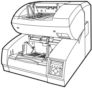
This section shows the exterior view and assemblies of the scanner. This section also provides names of each part and describes their functions.
Units
|
19 |
18 |
17 |
16 |
17 |
15 |
|
|
|
|
|
||
|
|
|
|
|
|
12 |
6 |
|
|
|
|
|
13 |
|
|
|
|
|
|
|
7 |
|
|
|
|
|
14 |
|
|
|
|
|
|
|
4 |
|
|
|
|
|
7 |
|
|
|
|
|
|
|
8 |
|
|
|
|
|
1 |
9 |
|
|
|
|
|
2 |
10 |
|
|
|
|
|
|
11 |
|
5 |
3 |
4 |
|
|
|
|
|
|
20
21
22
 1-2
1-2

No. |
Name |
Function |
|
|
|
1 |
Operator panel |
Used to operate the scanner. |
|
|
|
2 |
Power switch |
Used to power on or off. |
|
|
|
3 |
Hopper |
Document input tray. |
|
|
|
4 |
Hopper guides |
Used to adjust the document width. |
|
|
|
5 |
Hopper extension |
For use with long documents. |
|
|
|
6 |
Automatic document feeder (ADF) |
Feeds documents automatically. |
|
|
|
7 |
ADF release lever |
Used to open the ADF. |
|
|
|
8 |
Pick roller unit |
Picks top page in document stack. |
|
|
|
9 |
Guide plate |
The pad unit is mounted on. |
|
|
|
10 |
Pad |
Separates top page from document stack. |
|
|
|
11 |
Brake roller |
Separates top page from document stack. |
|
|
|
12 |
Upper transport unit |
Opens for easy access. |
|
|
|
13 |
Lever |
Used to open the upper transport unit. |
|
|
|
14 |
Side cover |
Opens to access back-side lamp. |
|
|
|
15 |
Stacker |
Document exit tray. |
|
|
|
16 |
Check stopper |
Adjustable stopper for shorter length documents. |
|
|
|
17 |
Stacker guides |
Helps guide documents into stacker. |
|
|
|
18 |
Stop lever |
Used to keep documents in the stacker. |
|
|
|
19 |
Stacker extension |
For use with long documents. |
|
|
|
20 |
Main line switch |
Controls supply of line power to the scanner. |
|
|
|
21 |
Power inlet |
Power cable connection. |
|
|
|
22 |
Interface connectors |
Ultra Wide SCSI (1pcs.) |
|
|
|
 1-3
1-3
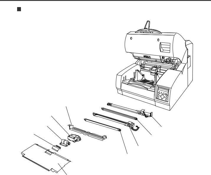
Assemblies
Lower sheet guide assembly
Pick roller unit
Brake roller
Lamp unit (back side)
Pad |
Lamp |
|
|
|
Lamp unit (front side) |
|
Lamp |
Guide plate
 1-4
1-4
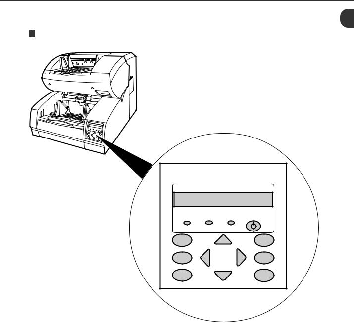
Operator Panel
The operator panel is located at the lower right hand side of the scanner. The panel consists of an LCD (24 character x 2 line), LEDs, and buttons.
Arrangement
Operator panel
|
|
LCD |
24 characters x 2 lines |
||
DATA |
CHECK |
POWER |
F1 |
|
MENU |
F2 |
|
ENTER |
F3 |
|
CANCEL |
 1-5
1-5
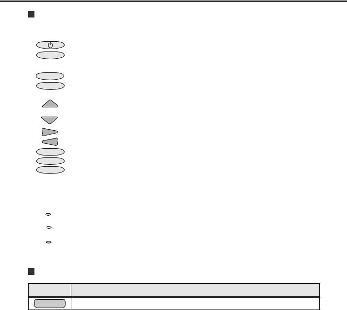
Button/LED Function
Button name |
Function |
|
|
|
|
|
Turns on or off the power when the main line switch is set to “I”. |
|
|
MENU |
Sets the scanner in setup or browse mode. It is also used to set test mode. (See Chapter 6) |
|
Setup mode is used for customizing the scanner. Browse mode is used for glancing conditions of the scanner. |
|
Test mode is used for testing the scanner offline. |
|
|
ENTER |
Used in setup, browse, or test mode. |
|
|
CANCEL |
• Clears an error if any. |
|
• Used in setup, browse, or test mode. |
|
|
|
• Lifts the hopper in normal mode without errors. |
|
• Used in setup, browse, or test mode. |
|
|
|
• Lowers the hopper in normal mode without errors. |
|
• Used in setup, browse, or test mode. |
|
|
|
Used in setup, browse, or test mode. |
|
|
|
Used in setup, browse, or test mode. |
|
|
F1 |
Available as shortcut keys when functions are defined in setup mode. |
F2 |
|
F3 |
|
|
|
LED |
Function |
|
|
|
|
POWER |
Lights when the power is on. |
|
|
DATA |
Lights when the image buffer contains data. |
|
|
|
|
CHECK |
Blinks when an equipment error occurs. |
|
|
|
|
LCD Display
LCD Function
Displays equipment status or error contents.
 1-6
1-6

Operation status display
After power is turned on, the LCD indicates the following messages in normal mode.
Please wait |
Wait for a moment. This is indicated when processing takes a long |
|
time. |
|
When this is displayed after turning power on, the second line |
|
indicates initializing messages. |
Ready |
The scanner can receive a command from the host computer or |
|
can be set in setup, browse, or test mode. |
Manual Feeding |
Load documents on the hopper table manually. |
Feeding |
The scanner is feeding documents. The second line indicates the |
|
number of documents fed per batch. |
Error status display
When the scanner detects errors, the LCD indicates the following messages. There are two types of errors: temporary errors and equipment errors.
Temporary errors (Ex.): |
The message is cleared just by following the next message. |
|
Hopper empty |
Mis-pick |
Cover open |
Equipment errors (Ex.): |
To clear the message, you must clean or replace the specified part. |
|
Optical error: Front |
Optical error: Back |
|
 1-7
1-7

Buzzer
The scanner has a buzzer to indicate that an error has occurred or an operator panel button is pressed. The buzzer function can be set on or off by following the procedure “Buzzer” in Chapter 6 SETUP, BROWSE, AND TEST MODES.
Sound condition |
Function |
Error occurred |
Sounds continuously. The buzzer turns off when any button is pressed or the |
|
power is turned off. Even when a button is pressed, the scanner continues |
|
to display the error. |
|
|
Button pressed |
Sounds briefly. This sound cannot be disabled by the buzzer setup. |
|
|
 1-8
1-8

CHAPTER
2
INSTALLATION AND CONNECTIONS
The chapter describes how to install and connect the scanner.
Precautions
Inspection
Cable Connection

Precautions
 WARNING
Place the machine with no portion of the scanner hangs over the desktop. Never attempt to move or relocate the machine without help. And hold the horizontal plane of the scanner bottom. (Not inclined plane)
 ACHTUNG
Stellen Sie den Scanner sicher auf eine waagerechte, ebene Flache. Bewegen Sie den Scanner nicht ohne Hilfe.
This section describes precautions when installing the scanner.
Do not install the scanner in the following places and environments.
•Place the scanner away from electrical noise sources, strong magnetic fields and air flow. If the scanner is used near an air conditioner, copying machine, or TV set, the scanner may operate incorrectly.
•Keep the scanner out of the sun and away from heaters. These environments may shorten the scanner life or cause hardware failures.
•Do not install the scanner in a place where vibrations may occur. This environment may cause hardware failures or may cause the scanner to operate incorrectly.
•Do not install the scanner in a humid, dusty, or damp places. These environments may shorten the scanner life or cause hardware failures. Do not place the scanner where liquid spills may occur.
•Be aware of the static electricity. Be sure that the flooring and the desk are made of materials that do not generate the static electricity.
See Chapter 5 SPECIFICATIONS for the information such as the size of the installation space.
 2-1
2-1
Inspection
This section describes how to check the labels.
Three labels
Label C |
Label A |
Label B |
Label A (An example)
 2-2
2-2

Label B (An example)
MODEL fi-4990C |
IMAGE SCANNER |
|
||
PART NO. CA04315-B107 |
AC100-240V |
|
||
SER. NO. |
|
|
1 phase |
50/60Hz |
DATE |
2001-02 |
|
2.9/1.5A |
65 kgf |
FUJITSU LIMITED |
|
MADE IN |
JAPAN |
|
Label C (An example)
MODEL NAME fi-4990C |
|
|
|
|
|
|
||||
PART NO. |
CA04315-B107 |
|
|
|
|
|||||
MODEL |
- 0 |
1 |
2 |
3 |
4 |
5 |
6 |
7 |
8 |
9 |
REV. |
- 0 |
1 |
2 |
3 |
4 |
5 |
6 |
7 |
8 |
9 |
|
- 0 1 2 3 4 5 6 7 8 9 |
|||||||||
 2-3
2-3
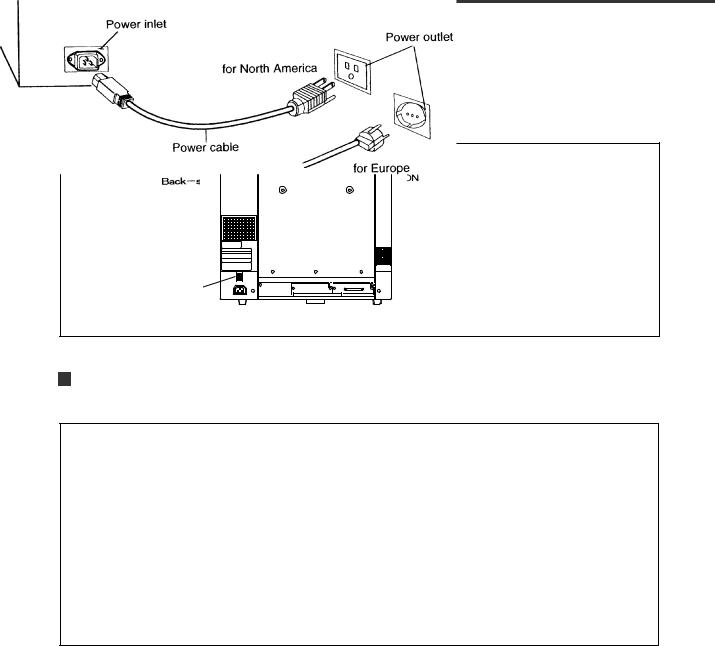
Cable Connection
This section describes how to connect the cables.
Connect the cables as follows:
Turning the main line switch off
Press “O” side of the main line switch to turn the power off.
Main line switch |
Connecting the power cable
Connect the power cable to the power inlet of the device and a power outlet.
 2-4
2-4

Connecting the interface cable
Connect the appropriate SCSI interface cables and secure them with hooks or screws.
Interface connector |
for SCSI |
Back – side |
Interface cable |
for SCSI |
 NOTE
NOTE
• SCSI-ID is set to No. 5 at shipment. Refer to Chapter 6 when changing the setting.
 2-5
2-5
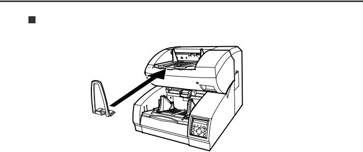
Attach the stop lever to the scanner.
Insert the stop lever to the scanner. (Into the gap in the stacker)
 2-6
2-6

CHAPTER
3
OPERATING INSTRUCTION
This chapter describes how to turn the power on, and also describes how to operate the operator panel (basic operation). Refer to Reference Guide about information on loading document and opening/closingtheuppertransportunit.
Turning the Power On
Basic Operation of the Operator Panel
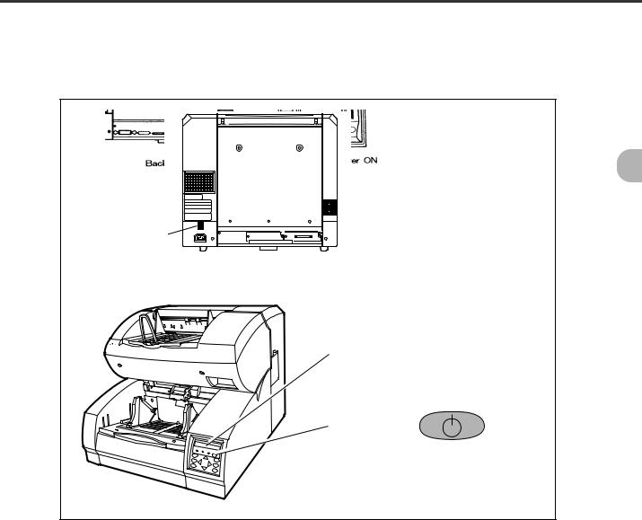
Turning the Power On
This section describes how to turn the power on.
Press “I” side of the main line switch located at the back of the scanner. Press the power switch of the operator panel. The power goes on and the green POWER lamp at the operator panel lights.
Main line switch |
Operator panel
Power switch
 3-1
3-1

Basic Operation of the Operator Panel
This section describes basic operation of the operator panel including how to enter the mode selection mode in which you can use setup mode, browse mode, and test mode.
Displaying detailed information if an error occurred
If an error occurs, the CHECK LED blinks and the error message is displayed on the LCD. For example, the LCD indicates as follows:
Hopper empty
Press CANCEL to clear the error (Temporaly errors will clear, equipment errors will not).
 3-2
3-2

Lifting or lowering the hopper
When the scanner has no error (the CHECK LED does not light), pressing  lifts the hopper and pressing
  lowers the hopper.
 CAUTION
During hopper height adjustment, do not touch the hopper table or do not put anything on the hopper table to prevent your fingers from being caught. If something is caught in the mechanism, the scanner may be damaged.
This function is valid when:
Ready |
is displayed. |
In details:
•The DATA LED does not light (the scanner contains no data),
•The scanning operation is not in progress,
•The scanner is not in test mode (except the offline feed test), and
•The scanner is not in setup or browse mode.
The hopper stops at the pick position or at the 250-, 500-, or 1000-sheet position depending on the hopper height adjustment in setup mode. At the pick position, the top paper of stack (the hopper table when no paper is loaded on the hopper) is aligned to the pick roller. At the 250-sheet position, for example, the hopper table can load about 250 sheets of paper.
Each time you press or
or , the hopper lifts or lowers by one position. Pressing
 when paper is loaded, the hopper lifts up to the pick position.
 3-3
3-3

Clearing a consumable life alarm
This scanner has the consumable counter to estimate consumable life of the scanner. When the consumable counter reaches the prescribed value, the LCD indicates an alarm that the consumable may be expired. For example, the following message appears:
Consumable life alarm
AAAAAAAA MMMM
In this case, press CANCEL . The LCD indicates the following message:
Reset Consumable Counter?
Yes:Enter No:Cancel
Yes (press ENTER
No (press CANCEL
): The scanner resets the consumable counter to zero.
): The scanner does not reset the consumable counter. In this case, the consumable life alarm recurs when the next sheet is fed.
 3-4
3-4
 Loading...