


TechNotes V1.0
Industrial Mainboard Series
Mini-ITX
D3433-S
D3434-S

Content
1 |
|
Safety Instructions |
|
|
6 |
|
|
|
|
|
|
|
|
2 |
|
Feature Overview |
|
|
7 |
|
|
|
|
|
|
|
|
2.1 |
Summary: Feature overview D343x-S |
|
|
7 |
|
|
|
|
|
|
|
|
|
2.2 |
Basic Layout & External Connectors D3433-S |
|
|
9 |
|
|
|
|
|
|
|
|
|
2.3 |
Basic Layout & External Connectors D3434-S |
|
|
10 |
|
|
|
|
|
|
|
|
|
2.4 |
Block Diagram D3433-S |
|
|
11 |
|
|
|
|
|
|
|
|
|
2.5 |
Block Diagram D3434-S |
|
|
12 |
|
|
|
|
|
|
|
|
|
2.6 |
Onboard components D3433-S & D3434-S |
|
|
13 |
|
|
|
|
|
|
|
|
|
2.7 |
I/O-Shield |
|
|
14 |
|
|
|
|
|
|
|
|
|
3 |
|
Interfaces & Connectors |
|
|
15 |
|
|
|
|
|
|
|
|
3.1 |
Frontpanel Connector |
|
|
15 |
|
|
|
|
|
|
|
|
|
3.2 |
Internal Serial (COM) Port Connector |
|
|
16 |
|
|
|
|
|
|
|
|
|
3.3 |
External Serial (COM) Port Connector |
|
|
16 |
|
|
|
|
|
|
|
|
|
3.4 |
Internal USB2.0 Connector (2 Ports) |
|
|
17 |
|
|
|
|
|
|
|
|
|
3.5 |
Internal USB3.0 Pin Connector (2 Ports) |
|
|
17 |
|
|
|
|
|
|
|
|
|
3.6 |
Internal USB3.0 Stick Socket |
|
|
18 |
|
|
|
|
|
|
|
|
|
3.7 |
External USB3.0 Connector |
|
|
18 |
|
|
|
|
|
|
|
|
|
3.8 |
PS/2 Keyboard Port |
|
|
19 |
|
|
|
|
|
|
|
|
|
3.9 |
PS/2 Mouse Port |
|
|
19 |
|
|
|
|
|
|
|
|
|
3.10 |
LAN Connector |
|
|
20 |
|
|
|
|
|
|
|
|
|
3.11 |
DVI-D Connector |
|
|
20 |
|
|
|
|
|
|
|
|
|
3.12 |
DisplayPort V1.2 Connector |
|
|
21 |
|
|
|
|
|
|
|
|
|
3.13 |
Embedded DisplayPort Connector |
|
|
22 |
|
|
|
|
|
|
|
|
|
3.14 |
Serial ATA Connector |
|
|
23 |
|
|
|
|
|
|
|
|
|
3.15 |
mSATA Pinout / Mini-PCIe Pinout – Fullsize |
|
|
24 |
|
|
|
|
|
|
|
|
|
3.16 |
mSATA / Mini-PCIe BIOS Setup Options |
|
|
25 |
|
|
|
|
|
|
|
|
|
3.17 |
m-SATA / Mini-PCIe Socket Assembly Note |
|
|
26 |
|
|
|
|
|
|
|
|
|
3.18 |
M.2 (Key M) – 2242 & 2260 |
|
|
27 |
|
|
|
|
|
|
|
|
|
|
|
|
|
|
|
|
|
|
TechNotes |
D343x-S V0.2 |
Page 2 of 88 |
http://www.fujitsu.com/fts/products/computing/pc/accessories/mainboards |
|

3.19 |
M.2 Socket Assembly Note |
|
|
28 |
|
|
|
|
|
|
|
|
|
3.20 |
Possible configurations for M.2 & Minicard –Modules |
|
|
29 |
|
|
|
|
|
|
|
|
|
3.21 |
PCIe x16 Slot Configuration for Riser cards (only supported for D3433-S) |
|
|
30 |
|
|
|
|
|
|
|
|
|
3.22 |
Fan Connectors |
|
|
31 |
|
|
|
|
|
|
|
|
|
3.23 |
Rear Audio / Frontpanel Audio Connector |
|
|
32 |
|
|
|
|
|
|
|
|
|
3.24 |
S/PDIF Connector |
|
|
34 |
|
|
|
|
|
|
|
|
|
3.25 |
GPIO (Feature Connector) |
|
|
35 |
|
|
|
|
|
|
|
|
|
3.26 |
Power Supply Connector (Multirail) |
|
|
36 |
|
|
|
|
|
|
|
|
|
3.27 |
Additional Power Supply Connector (12V for Processor) |
|
|
36 |
|
|
|
|
|
|
|
|
|
3.28 |
Power Supply Connectors (ATX Multirail or Single 12V Operation) |
|
|
37 |
|
|
|
|
|
|
|
|
|
3.28.1 |
ATX Multirail Operation |
|
|
37 |
|
|
3.28.2 |
Single 12V Operation |
|
|
38 |
|
|
3.28.3 |
Single 12V Operation – Config |
|
|
39 |
|
|
3.29 |
Chassis Intrusion |
|
|
40 |
|
|
|
|
|
|
|
|
|
4 |
|
System Monitoring |
|
|
41 |
|
|
|
|
|
|
|
|
4.1 |
D343x-S: Temperature Sensors and Fan Connectors (preliminary) |
|
|
42 |
|
|
|
|
|
|
|
|
|
4.2 |
SystemGuard |
|
|
43 |
|
|
|
|
|
|
|
|
|
4.3 |
SystemGuard - Details |
|
|
44 |
|
|
|
|
|
|
|
|
|
4.4 |
SilentFanConfigManager – Customize System Monitoring Settings |
|
|
45 |
|
|
|
|
|
|
|
|
|
4.5 |
Components for continous 24/7 operation @ +60°C |
|
|
46 |
|
|
|
|
|
|
|
|
|
4.6 |
Capacitor Endurance Time Comparison |
|
|
47 |
|
|
|
|
|
|
|
|
|
4.7 |
Temperature Reference Points D343x-S |
|
|
48 |
|
|
|
|
|
|
|
|
|
4.8 |
Temperature Reference Points D343x-S (rear) |
|
|
49 |
|
|
|
|
|
|
|
|
|
4.9 |
BMC – BIOS Default Settings D343x-S |
|
|
50 |
|
|
|
|
|
|
|
|
|
5 |
|
Power Supply |
|
|
51 |
|
|
|
|
|
|
|
|
5.1 |
ATX Power Supply |
|
|
51 |
|
|
|
|
|
|
|
|
|
5.2 |
Typcial Power Consumption (to be added soon) |
|
|
52 |
|
|
|
|
|
|
|
|
|
6 |
|
USB Implementation |
|
|
53 |
|
|
|
|
|
|
|
|
6.1 |
USB Ports & USB Power Fuses (D3433-S) |
|
|
53 |
|
|
|
|
|
|
|
|
|
6.2 |
USB Ports & USB Power Fuses (D3434-S) |
|
|
55 |
|
|
|
|
|
|
|
|
|
7 |
|
Display Options |
|
|
57 |
|
|
|
|
|
|
|
|
7.1 |
Summary: Video Output Options D343x-S |
|
|
57 |
|
|
|
|
|
|
|
|
|
7.2 |
LVDS Display & Backlight Inverter |
|
|
59 |
|
|
|
|
|
|
|
|
|
7.3 |
LVDS Connector Details |
|
|
60 |
|
|
|
|
|
|
|
|
|
|
|
|
|
|
|
|
|
|
TechNotes |
D343x-S V0.2 |
Page 3 of 88 |
http://www.fujitsu.com/fts/products/computing/pc/accessories/mainboards |
|

7.4 |
Backlight Inverter Connector Details |
|
|
61 |
|
|
|
|
|
|
|
|
|
7.5 |
LVDS Timing & Screen Resolution |
|
|
62 |
|
|
|
|
|
|
|
|
|
7.6 |
LVDS Tool |
|
|
65 |
|
|
|
|
|
|
|
|
|
7.7 |
LVDS – Influence on Graphics Output (prelim.) |
|
|
66 |
|
|
|
|
|
|
|
|
|
7.8 |
LVDS Cabling Reference |
|
|
67 |
|
|
|
|
|
|
|
|
|
7.9 |
LVDS Sample Cabling for AuO-G150 |
|
|
68 |
|
|
|
|
|
|
|
|
|
7.10 |
Embedded DisplayPort (prelim.) |
|
|
69 |
|
|
|
|
|
|
|
|
|
7.11 |
Embedded Display Port Power |
|
|
70 |
|
|
|
|
|
|
|
|
|
8 |
|
Operating System Support |
|
|
71 |
|
|
|
|
|
|
|
|
8.1 |
Support for Windows 7 / Windows 8.1 / Windows 10 |
|
|
72 |
|
|
|
|
|
|
|
|
|
8.2 |
Linux Support (to be added soon) |
|
|
73 |
|
|
|
|
|
|
|
|
|
9 |
|
Mainboard Tools |
|
|
74 |
|
|
|
|
|
|
||
Common Mainboard Tools |
|
|
74 |
|
||
|
|
|
|
|
|
|
9.1 |
BIOS Boot Logo Tool |
|
|
74 |
|
|
|
|
|
|
|
|
|
9.2 |
EditCMOS |
|
|
74 |
|
|
|
|
|
|
|
|
|
9.3 |
OEMIDENT |
|
|
74 |
|
|
|
|
|
|
|
|
|
9.4 |
SystemGuard |
|
|
75 |
|
|
|
|
|
|
|
||
Industrial Tools |
|
|
76 |
|
||
|
|
|
|
|
|
|
9.5 |
SilentFanConfig-Manager |
|
|
76 |
|
|
|
|
|
|
|
|
|
9.6 |
Windows System-Monitoring API (BMCAPI) |
|
|
77 |
|
|
|
|
|
|
|
|
|
9.7 |
Linux System-Monitoring Driver (“LM-Sensors”) To be added soon |
|
|
77 |
|
|
|
|
|
|
|
|
|
10 |
Known Issues & Important Notes |
|
|
78 |
|
|
|
|
|
|
|
|
|
10.1 |
USB 2.0 / MS Windows 7 |
|
|
78 |
|
|
|
|
|
|
|
|
|
10.2 |
TPM2.0 / MS Windows 7 |
|
|
78 |
|
|
|
|
|
|
|
|
|
11 |
Miscellaneous |
|
|
79 |
|
|
|
|
|
|
|
|
|
11.1 |
Battery Lifetime |
|
|
79 |
|
|
|
|
|
|
|
|
|
11.2 |
RealTime Clock (RTC) Accuracy |
|
|
80 |
|
|
|
|
|
|
|
|
|
11.3 |
System Watchdog (WD) |
|
|
81 |
|
|
|
|
|
|
|
|
|
11.4 |
BIOS Update / BIOS Recovery |
|
|
84 |
|
|
|
|
|
|
|
|
|
11.5 |
BIOS/CMOS: Reset Defaults |
|
|
85 |
|
|
|
|
|
|
|
|
|
11.6 |
BIOS integrated HW Diagnostic Tool |
|
|
86 |
|
|
|
|
|
|
|
|
|
11.7 |
BIOS integrated Erase Disk Tool |
|
|
86 |
|
|
|
|
|
|
|
|
|
11.8 |
Power indicator |
|
|
87 |
|
|
|
|
|
|
|
|
|
|
|
|
|
|
|
|
|
|
TechNotes |
D343x-S V0.2 |
Page 4 of 88 |
http://www.fujitsu.com/fts/products/computing/pc/accessories/mainboards |
|

Revision History:
V1.0 |
First Version |
22.02.2016 |
Technical data are subject to change without prior notice. Fujitsu accepts no responsibility with regards to technical or editorial mistakes or omissions.
TechNotes |
D343x-S V0.2 |
Page 5 of 88 |
http://www.fujitsu.com/fts/products/computing/pc/accessories/mainboards |
Safety Instructions
1 Safety Instructions
Do not connect or disconnect any cables or modules to or from any onboard connectors (except for the rear I/O connectors) until the mainboard is completely powered down.
Any damage caused to the mainboard by misuse of the onboard connectors is excluded from the standard warranty. Fujitsu Technology Solutions cannot be held liable for any damage that results from incorrect use of any onboard connectors.
The system integrator is fully responsible for the usage of appropriate connectors and cables in order to fulfill the technical requirements (electrical contact, durability, power/current levels, signal integrity etc.)
TechNotes D307x-S V1.1 |
3 |
Copyright 2011 FUJITSU |
TechNotes |
D343x-S V0.2 |
Page 6 of 88 |
http://www.fujitsu.com/fts/products/computing/pc/accessories/mainboards |

2 Feature Overview
2.1 Summary: Feature overview D343x-S
Feature |
D3433-S |
D3434-S |
Note |
|
|
|
|
|
|
Chipset (PCH) |
Q170 |
H110 |
incl. heatsink |
|
|
|
|
|
|
Memory Sockets / max. RAM / ECC Support |
2 / 32GB DDR4-2133 |
2 / 32GB DDR4-2133 |
SO-DIMM |
|
/ Non-ECC |
/ Non-ECC |
|||
|
|
|||
Intel® Core™ i7 / i5 / i3 – (6th gen.) processor series (max. 65W TDP) |
x |
x |
K-Series not supported! |
|
|
|
|
|
|
Intel® Pentium® / Celeron® processor series (max. 65W TDP) |
x |
x |
|
|
|
|
|
|
|
TPM V1.2 / TPM V2.0 |
-- / Infineon |
-- / Intel integrated |
|
|
|
|
|
|
|
mSATA Socket 1) / Mini-PCIe Socket 1) / 8 Bit GPIO |
x / x / x |
-- / x / x |
halfsize / fullsize possible, |
|
|
|
|
incl. USB2.0 |
|
|
PCIe x2 & SATA based M.2 |
SATA based M.2 |
Mechanical support for |
|
M.2 Socket |
42mm and 60mm modules; |
|||
modules supported |
modules supported |
|||
|
Key M |
|||
|
|
|
||
USB2.0 Ports internal / external |
2 / 4 |
2 / 3 |
|
|
|
|
|
|
|
USB3.0 Ports internal / external / USB 3.0 Stick Socket onboard |
2 / 4 / x |
2 / 2 / - |
|
|
|
|
|
|
|
Fan 1 /2 / 3 / 4 |
x / -- / x / -- |
x / -- / x / -- |
|
|
|
|
|
|
|
FAN3: PWM or 3Pin |
x |
x |
BIOS Setup option |
|
|
|
|
|
|
Onboard LVDS 24bit / eDP (2 lanes) |
x / x |
x / x |
Simultaneous use possible |
|
|
|
|
|
|
SATA3 / RAID Support (0/1/5/10) |
4 / x |
2 / -- |
|
|
|
|
|
|
|
S/P-DIF / Intrusion |
x / x |
x / x |
|
|
|
|
|
|
1) Shared socket mSATA / Mini-PCIe
TechNotes |
D343x-S V0.2 |
Page 7 of 88 |
http://www.fujitsu.com/fts/products/computing/pc/accessories/mainboards |

Feature Overview
Summary: Feature overview D343x-S (continued)
Feature |
D3433-S |
D3434-S |
Notes |
|
|
|
|
|
|
|
Gen3; Support for lane split |
Gen3 |
|
|
Slot #1: PCIe x16 (PEG Slot) |
Riser: 2x PCIe x8 or 1x |
|
||
No lane split support |
|
|||
|
PCIe8 and 2x PCIe4 |
|
||
|
|
|
||
COM-Port external / COM-Port internal / Parallel Port internal |
1 / 1 / -- |
1 / 1 / -- |
|
|
|
|
|
|
|
DVI-I / DVI-D / DisplayPort 1 / DisplayPort 2 / LVDS / Emb. DisplayPort |
-- / x / x / x / x / x |
-- / x / x / -- / x / x |
Up to 3 independent displays |
|
(D3434 / H110: max. 2) |
||||
|
|
|
||
Dual LAN / Intel iAMT 11 - vPro 2015 Manageability 1) |
x / x |
x / -- |
Incl. Teaming Support; |
|
BIOS-POST / BIOS-Boot / OS – HW Watchdog onboard |
x / x / x |
x / x / x |
|
|
|
|
|
|
|
|
|
|
Improved electrical signal |
|
8 Layer PCB |
x |
x |
quality & |
|
|
|
|
improved durability |
|
Approved for 24/7 operation @ 60°C / full load |
x |
x |
|
|
|
|
|
|
|
UL/CSA 60950-1 certification |
planned |
planned |
|
|
|
|
|
|
|
FCC/B approval |
planned |
planned |
|
|
|
|
|
|
|
EraseDisk (BIOS Feature) included |
x |
x |
|
|
|
|
|
|
1) iAMT (Q170) requires appropriate Core i5 / Core i7 processor;
TechNotes |
D343x-S V0.2 |
Page 8 of 88 |
http://www.fujitsu.com/fts/products/computing/pc/accessories/mainboards |
Feature Overview
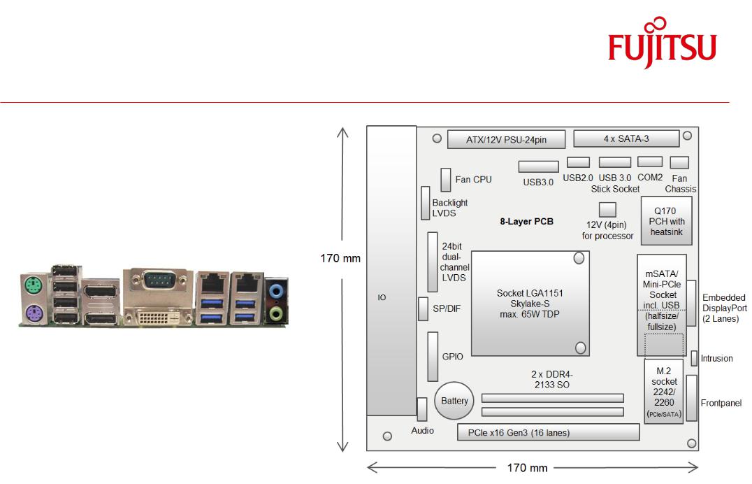
2.2 Basic Layout & External Connectors D3433-S
Mouse 4x USB2.0 |
COM1 |
LAN2 |
LAN1 (iAMT) |
Kbd |
2x DisplayPort V1.2 |
DVI-D |
4x USB 3.0 |
Audio |
TechNotes |
D343x-S V0.2 |
Page 9 of 88 |
http://www.fujitsu.com/fts/products/computing/pc/accessories/mainboards |
Feature Overview
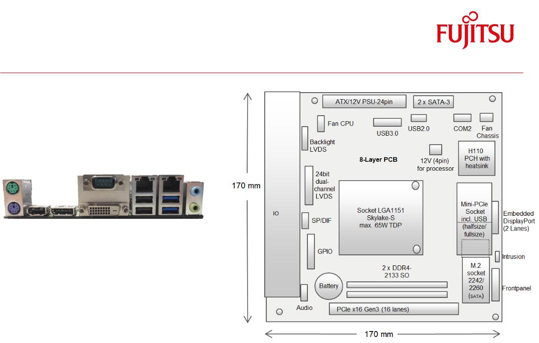
2.3 Basic Layout & External Connectors D3434-S
Mouse |
1x USB2.0 |
COM1 |
LAN2 |
LAN1 |
Kbd |
1x DisplayPort V1.2 |
DVI-D |
2x USB 2.0 2x USB 3.0 Audio |
TechNotes |
D343x-S V0.2 |
Page 10 of 88 |
http://www.fujitsu.com/fts/products/computing/pc/accessories/mainboards |
Feature Overview
2.4 Block Diagram D3433-S
TechNotes |
D343x-S V0.2 |
Page 11 of 88 |
http://www.fujitsu.com/fts/products/computing/pc/accessories/mainboards |
Feature Overview
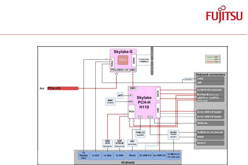
2.5 Block Diagram D3434-S
TechNotes |
D343x-S V0.2 |
Page 12 of 88 |
http://www.fujitsu.com/fts/products/computing/pc/accessories/mainboards |
Feature Overview
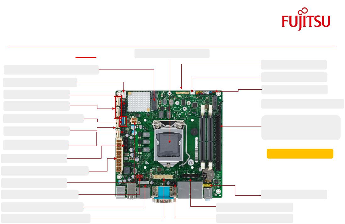
2.6 Onboard components D3433-S & D3434-S |
CPU LGA1151 max. 65W |
mSATA(D3433-S only) / Mini-PCIe |
|
Fan3 (4 pin PWM / 3 pin) |
|
COM2 Port |
|
4 x SATA-III = D3433-S |
|
USB 3.0 Socket (D3433-S only) |
|
2 x SATA-III = D3434-S |
|
2 x USB 2.0 (Internal) |
|
2x USB 3.0 (Frontpanel) |
|
24 pin ATX PSU / 12V DC Supply |
|
12V Supply (Processor) |
|
Processor Fan (4 Pin) |
|
Backlight LVDS |
|
24bit dual channel LVDS |
|
eDP (2Lanes)
Intrusion
Frontpanel
 M.2 - SATA / PCIe (D3433-S only)
PCIe x16 (16 Lanes, Gen3) D3433-S only: Lane split supported
8 Layer PCB
Frontpanel Audio
GPIO Port
S/PDIF Output
TechNotes |
D343x-S V0.2 |
Page 13 of 88 |
http://www.fujitsu.com/fts/products/computing/pc/accessories/mainboards |
Feature Overview
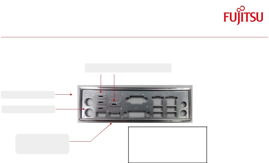
2.7 I/O-Shield
Spring Steel Sheet
Enforcement Sheet
Rear Side: EMI Gasket (Foam with Copper Nickel fabric)
USB/DP-cover to be removed for D3433-S
Nominal force: ~ 75 N
for specified ATX IO “letterbox”
Note: ATX Chassis “letterbox” for I/O shield:
Nom. size = 158.75 x 44.45mm
Tolerance = +/- 0.2mm
TechNotes |
D343x-S V0.2 |
Page 14 of 88 |
http://www.fujitsu.com/fts/products/computing/pc/accessories/mainboards |
3 Interfaces & Connectors
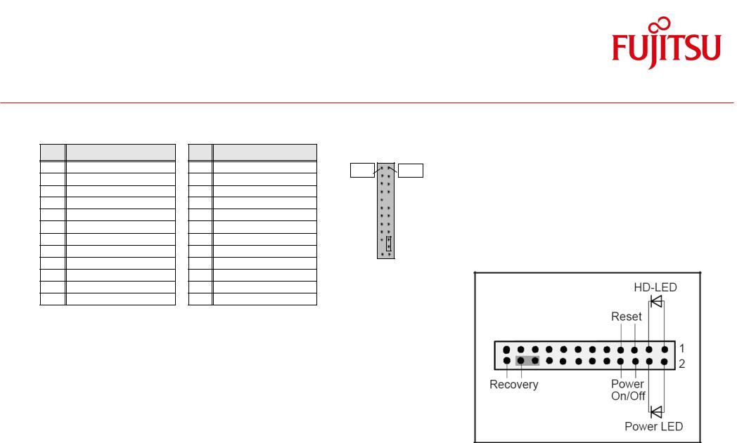
3.1 Frontpanel Connector
Pin |
Signal |
Pin |
Signal |
|
|
1 |
HD-LED + |
2 |
Power LED + |
Pin 1 |
Pin 2 |
3 |
HD-LED - |
4 |
Power LED - |
|
|
5 |
GND |
6 |
Power_Button |
|
|
7 |
RST_L |
8 |
GND |
|
|
9 |
reserved |
10 |
Key |
|
|
11 |
reserved |
12 |
GND |
|
|
13 |
BMC Alert LED + |
14 |
BMC Alert LED - |
|
|
15 |
reserved |
16 |
reserved |
|
|
17 |
Speaker + |
18 |
BIOS Testmode (reserved) |
|
|
19 |
GND |
20 |
GND (0,1K) |
|
|
21 |
Key |
22 |
GND (0,1K) |
|
|
23 |
Speaker - |
24 |
Recover BIOS |
|
|
Power LED:
Anode: Pin 2 – current source 3mA up to 4V
Cathode: Pin 4 (suitable for various LED colors)
HDD LED:
Anode: Pin 1 – current source 3mA up to 4V
Cathode: Pin 3 (suitable for various LED colors)
Internal Speaker Output:
Differential audio signal; mono, max. 2W RMS / 4Ohm
Note: System Beeps are audible via the internal speaker output only,
even if a device is connected to the external audio ports (rear/front) .
TechNotes |
D343x-S V0.2 |
Page 15 of 88 |
http://www.fujitsu.com/fts/products/computing/pc/accessories/mainboards |

Interfaces & Connectors
3.2 Internal Serial (COM) Port Connector
Pin |
Signal |
|
Pin |
Signal |
1 |
DCD 2 |
|
2 |
DSR 2 |
3 |
SIN 2 |
|
4 |
RTS 2 |
5 |
SOUT 2 |
|
6 |
CTS 2 |
7 |
DTR 2 |
|
8 |
RI 2 |
9 |
GND |
|
10 |
Key |
Note: D3433/34: The internal COM-Port is COM2
3.3 External Serial (COM) Port Connector
Pin |
Signal |
|
Pin |
Signal |
|
|
|
|
|
1 |
DCD 1 |
|
6 |
DSR 1 |
2 |
SIN 1 |
|
7 |
RTS 1 |
3 |
SOUT 1 |
|
8 |
CTS 1 |
4 |
DTR 1 |
|
9 |
RI 1 |
5 |
GND |
|
|
|
Pin 1 |
|
|
|
Pin 2 |
|
||||
|
|
|
|
|
|
|
|
|
|
|
|
|
|
|
|
|
|
|
|
|
|
|
|
|
Pin 1
Pin 6
TechNotes |
D343x-S V0.2 |
Page 16 of 88 |
http://www.fujitsu.com/fts/products/computing/pc/accessories/mainboards |
Interfaces & Connectors |
|
|
|
|
|
|
|
|
|
|
|
|
|
|
|
|
||||||||||||||
3.4 Internal USB2.0 Connector (2 Ports) |
|
|
|
|
|
|
|
|
|
|
|
|
|
|
|
|
||||||||||||||
|
|
|
|
|
|
|
|
|
|
|
|
|
|
Note: |
|
|||||||||||||||
|
|
|
|
|
|
|
|
|
|
|
|
|
|
|
|
|
|
|
|
|
|
|
|
|
|
|
|
|
|
|
|
|
|
|
|
|
|
|
|
|
|
|
|
|
|
|
|
|
|
|
|
|
|
|
|
|
|
|
|
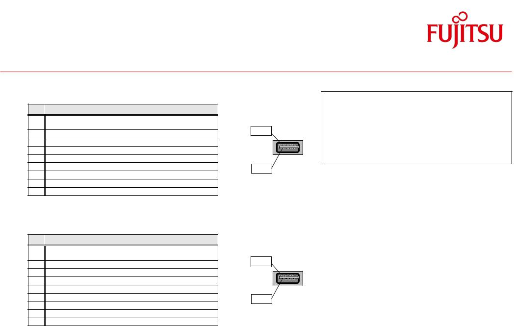
All USB3 connectors provide separate signal |
|
|
|
|
|
|
|
|
|
|
|
|
|
|
|
|
|
|
|
|
|
|
|
|
|
|
|
|
|
|
lines for USB3.0 and USB2.0! |
|
|
Pin |
|
|
Signal |
|
|
|
Pin |
|
Signal |
|
|
|
|
|
|||||||||||||||
|
|
|
|
|
|
|
|
|
|
|
|
|
|
|
|
|
|
|
|
|
|
|
|
|||||||
|
1 |
|
|
VCC AUX (fuse protected) |
|
|
2 |
|
|
VCC AUX (fuse protected) |
|
|
Pin 1 |
|
|
|
|
Pin 2 |
|
|
|
|
|
All “fused” ports provide max. 500mA |
|
|||||
|
|
|
|
|
|
|
|
|
|
|
|
|
|
|
|
|
|
|
||||||||||||
|
|
|
|
|
|
|
|
|
|
|
|
|
|
|
|
|
|
|
|
|
|
|||||||||
|
3 |
|
|
Data negative Port X |
|
|
4 |
|
|
Data negative Port Y |
|
|
|
|
|
|
|
|
|
|
|
|
|
|
|
|||||
|
5 |
|
|
Data positive Port X |
|
|
6 |
|
|
Data positive Port Y |
|
|
|
|
|
|
|
|
|
|
|
|
|
|
(USB2.0) resp. . 900mA (USB3.0) for each |
|
||||
|
7 |
|
|
GND |
|
|
8 |
|
|
GND |
|
|
|
|
|
|
|
|
|
|
|
|
|
|
port |
|
||||
|
|
|
|
|
|
|
|
|
|
|
|
|
|
|
|
|
||||||||||||||
|
9 |
|
|
Key |
|
|
10 |
|
|
Not connected |
|
|
|
|
|
|
|
|
|
|
|
|
|
|
|
|
||||
3.5 Internal USB3.0 Pin Connector (2 Ports) |
|
|
|
|
|
|
|
|
|
|
|
|
|
|
|
|
||||||||||||||
|
|
|
|
|
|
|
|
|
|
|
|
|
|
|
|
|||||||||||||||
|
|
|
|
|
|
|
|
|
|
|
|
|
|
|
|
|
|
|
|
|
|
|
|
|
|
|||||
|
Pin |
|
|
Signal |
|
|
Pin |
|
|
Signal |
|
|
|
|
|
|
|
|
|
|
|
|
|
|
|
|
||||
|
|
|
|
|
|
|
|
|
|
|
|
|
|
|
|
|
|
|
Pin 1 |
|
|
|
||||||||
|
1 |
|
|
VCC AUX (polyswitch fused and power |
|
2 |
|
|
|
USB3_RX negative (P2) |
|
|
|
|
|
|
Pin 19 |
|
|
|
|
|
|
|
|
|||||
|
|
|
|
|
|
|
|
|
|
|
|
|
|
|
|
|
|
|
|
|
||||||||||
|
|
|
|
supervision with over current detection) |
|
|
|
|
|
|
|
|
|
|
|
|
|
|
|
|
|
|
|
|
|
|
|
|||
|
|
|
|
|
|
|
|
|
|
|
|
|
|
|
|
|
|
|
|
|
|
|
|
|
|
|
||||
|
3 |
|
|
USB3_RX positive (P2) |
|
4 |
|
|
|
GND |
|
|
|
|
|
|
|
|
|
|
|
|
|
|
|
|
||||
|
5 |
|
|
USB3_TX negative (P2) |
|
6 |
|
|
|
USB3_TX positive (P2) |
|
|
|
|
|
|
|
|
|
|
|
|
|
|
|
|
||||
|
7 |
|
|
GND |
|
8 |
|
|
|
Data negative (P2) [USB2.0] |
|
|
|
|
|
|
|
|
|
|
|
|
|
|
|
|
||||
|
9 |
|
|
Data positive (P2) [USB2.0] |
|
10 |
|
|
|
FP Detect |
|
|
|
|
|
|
|
|
|
|
|
|
|
|
|
|
||||
|
11 |
|
|
Data positive (P3) [USB2.0] |
|
|
|
|
Data negative (P3) [USB2.0] |
|
|
|
|
|
|
|
|
|
|
|
|
|
|
|
|
|||||
|
13 |
|
|
GND |
|
14 |
|
|
|
USB3_TX positive (P3) |
|
|
|
|
|
|
|
|
|
|
|
|
|
|
|
|
||||
|
15 |
|
|
USB3_TX negative (P3) |
|
16 |
|
|
|
GND |
|
|
|
|
|
|
|
|
|
|
|
|
|
|
|
|
||||
|
17 |
|
|
USB3_RX positive (P3) |
|
18 |
|
|
|
USB3_RX negative (P3) |
|
|
|
|
|
|
|
|
|
|
|
|
|
|
|
|
||||
|
19 |
|
|
VCC AUX (polyswitch fused and power |
|
|
|
|
|
|
|
|
|
|
|
|
|
|
|
|
|
|
|
|
|
|
|
|||
|
|
|
|
supervision with over current detection) |
|
|
|
|
|
|
|
|
|
|
|
|
|
|
|
|
|
|
|
|
|
|
|
|||
TechNotes |
D343x-S V0.2 |
Page 17 of 88 |
http://www.fujitsu.com/fts/products/computing/pc/accessories/mainboards |
Interfaces & Connectors
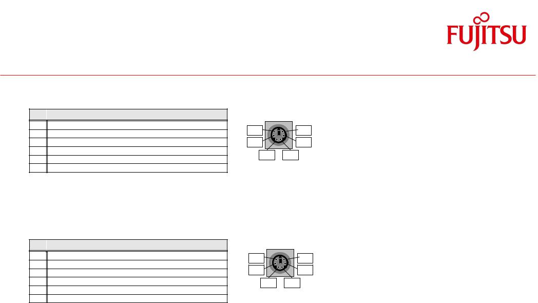
3.6 Internal USB3.0 Stick Socket
Pin 
 Signal
1VCC auxiliary
(polyswitch fused and power supervision with over current detection)
2Data negative [USB2.0]
3Data positive [USB2.0]
4GND
5USB3_RX negative
6USB3_RX positive
7GND
8USB3_TX negative
9USB3_TX positive
3.7External USB3.0 Connector
Pin 
 Signal
1VCC auxiliary
(polyswitch fused and power supervision with over current detection)
2Data negative [USB2.0]
3Data positive [USB2.0]
4GND
5USB3_RX negative
6USB3_RX positive
7GND
8USB3_TX negative
9USB3_TX positive
Note:
All USB3 connectors provide separate signal lines for USB3.0 and USB2.0!
Pin 9
All “fused” ports provide max. 500mA (USB2.0) resp. . 900mA (USB3.0) for each port
Pin 1
Pin 9
Pin 1
TechNotes |
D343x-S V0.2 |
Page 18 of 88 |
http://www.fujitsu.com/fts/products/computing/pc/accessories/mainboards |
Interfaces & Connectors
3.8 PS/2 Keyboard Port
Pin 
 Signal
1KBD Data
2Not connected
3GND
4VCC (polyswitch fused)
5KBD CLK
6Keyboard_On (low asserted pulse)
3.9PS/2 Mouse Port
Pin 
 Signal
1MOUSE Data
2Not connected
3GND
4VCC (polyswitch fused)
5MOUSE CLK
6Not connected
Pin 6 |
Pin 5 |
Pin 4 |
Pin 3 |
Pin 2 |
Pin 1 |
Pin 6 |
Pin 5 |
Pin 4 |
Pin 3 |
Pin 2 |
Pin 1 |
TechNotes |
D343x-S V0.2 |
Page 19 of 88 |
http://www.fujitsu.com/fts/products/computing/pc/accessories/mainboards |
Interfaces & Connectors
3.10 LAN Connector
Pin |
|
Signal with 10/100/1000 |
|
Signal with 10/100 |
|
|
|
|
|
|
|
|
|
|
|
|
|
|
|
|
|
1 |
|
MX1 + |
|
TX + |
|
|
|
|
|
|
|
|
|
|
|
|
|
|
|
|
|
2 |
|
MX1 - |
|
TX - |
|
|
|
|
|
|
3 |
|
MX2 + |
|
RX + |
|
|
|
|
|
|
|
|
|
|
|
|
|
|
|||
4 |
|
MX3 + |
|
TERMPLANE |
|
|
|
|
|
|
5 |
|
MX3 - |
|
TERMPLANE |
|
|
|
|
|
Pin 1 |
6 |
|
MX2 - |
|
RX - |
|
|
|
|
|
|
7 |
|
MX4 + |
|
TERMPLANE |
|
|
|
|
|
|
8 |
|
MX4 - |
|
TERMPLANE |
|
|
|
|
|
|
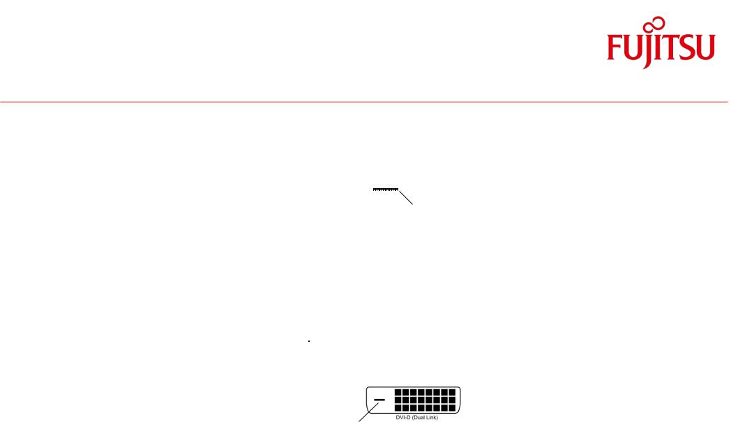
3.11 DVI-D Connector
Pin |
Signal |
|
Pin |
Signal |
1 |
Data2+ |
|
13 |
NC |
2 |
Data2- |
|
14 |
Vcc (fused) |
3 |
GND |
|
15 |
ND |
4 |
NC |
|
16 |
Hot_Plug_detect |
5 |
NC |
|
17 |
Data0- |
6 |
DDC_CLK |
|
18 |
Data0+ |
7 |
DDC_DAT |
|
19 |
GND |
8 |
NC |
|
20 |
NC |
9 |
Data1- |
|
21 |
NC |
10 |
Data1+ |
|
22 |
GND |
11 |
GND |
|
23 |
CLK+ |
12 |
NC |
|
24 |
CLK- |
C5 |
GND |
|
C3 |
Blue (DVI-I) |
C1 |
Red (DVI-I) |
|
C4 |
H-Sync (DVI-I) |
C2 |
Green (DVI-I) |
|
|
|
C5
Note: Supports Single-Link only!
TechNotes |
D343x-S V0.2 |
Page 20 of 88 |
http://www.fujitsu.com/fts/products/computing/pc/accessories/mainboards |
Interfaces & Connectors
3.12 DisplayPort V1.2 Connector
Pin |
|
Signal |
|
Pin |
|
Signal |
|
|
|
|
|
|
|
|
1 |
|
Link0+ |
|
11 |
|
GND |
|
19 |
|
|
1 |
|
|
|
|
|
|
|
|
|
|
|
|
|
|
||||
|
|
|
|
|
|
|
|
|
|
|
|
|
|
|
2 |
|
Link0- |
|
12 |
|
Link1+ |
|
|
|
|
|
|
|
|
|
|
|
|
|
|
|
|
|
|
|
||||
3 |
|
GND |
|
13 |
|
Link1- |
|
|
|
|
|
|
|
|
4 |
|
Link2+ |
|
14 |
|
GND |
|
20 |
|
|
2 |
|
|
|
|
|
|
|
|
|
|
|
|
|
|
||||
|
|
|
|
|
|
|
|
|
|
|
||||
5 |
|
Link2- |
|
15 |
|
Link3+ |
|
|
|
|
|
|
|
|
6 |
|
GND |
|
16 |
|
Link3- |
|
|
|
|
|
|
|
|
7 |
|
DVI dongle detect / (GND |
|
17 |
|
GND / (CEC for HDMI (N/A)) |
|
|
|
|
|
|
|
|
|
|
(N/A)) |
|
|
|
|
|
|
|
|
|
|
|
|
8 |
|
AUX+ |
|
18 |
|
GND |
|
|
|
|
|
|
|
|
9 |
|
AUX- |
|
19 |
|
Hotplug detect |
|
|
|
|
|
|
|
|
10 |
|
GND (Return) |
|
20 |
|
P3V3P |
|
|
|
|
|
|
|
|
TechNotes |
D343x-S V0.2 |
Page 21 of 88 |
http://www.fujitsu.com/fts/products/computing/pc/accessories/mainboards |

Interfaces & Connectors
3.13 Embedded DisplayPort Connector
Pi |
|
Signal Assignment |
Comment |
1 |
|
NC |
|
2 |
|
GND |
|
3 |
|
Link1- |
|
4 |
|
Link1+ |
|
5 |
|
GND |
|
6 |
|
Link0- |
|
7 |
|
Link0+ |
|
8 |
|
GND |
|
9 |
|
AUX+ |
|
10 |
|
AUX- |
|
11 |
|
GND |
|
12 |
|
LCD VCC |
3,3V or 5V |
13 |
|
LCD VCC |
|
|
|
||
14 |
|
NC |
|
15 |
|
LCD GND |
|
Pi |
|
Signal Assignment |
Comment |
|
|
|
|
16 |
|
LCD GND |
|
|
|
|
|
17 |
|
Hotplug detect |
|
|
|
|
|
18 |
|
Backl. GND |
|
|
|
|
|
19 |
|
Backl. GND |
|
|
Pin 1 |
|
Pin 30 |
|
|
|
|
|
|
||
20 |
|
Backl. GND |
|
|
|
|
|
|
|
|
|
|
|
||
21 |
|
Backl. GND |
|
|
|
|
|
22 |
|
Backl enable |
activ high |
|
|
|
|
23 |
|
Backl PWM / Dimm |
|
|
|
|
|
24 |
|
NC |
|
|
|
|
|
25 |
|
NC |
|
|
|
|
|
26 |
|
Backl 12V |
|
|
|
|
|
27 |
|
Backl 12V |
|
|
|
|
|
28 |
|
Backl 12V |
|
|
|
|
|
29 |
|
Backl 12V |
|
|
|
|
|
30 |
|
NC |
|
|
|
|
|
Note: Connector type:
Onboard: I-PEX: 20455-030E-12 (or compatible)
eDP Cable (mating housing): I-PEX: 20453-030T-11 (or compatible) Cable requires 1:30 connection (pin 1 to pin 30, pin2 to pin29 etc.)
TechNotes |
D343x-S V0.2 |
Page 22 of 88 |
http://www.fujitsu.com/fts/products/computing/pc/accessories/mainboards |

Interfaces & Connectors
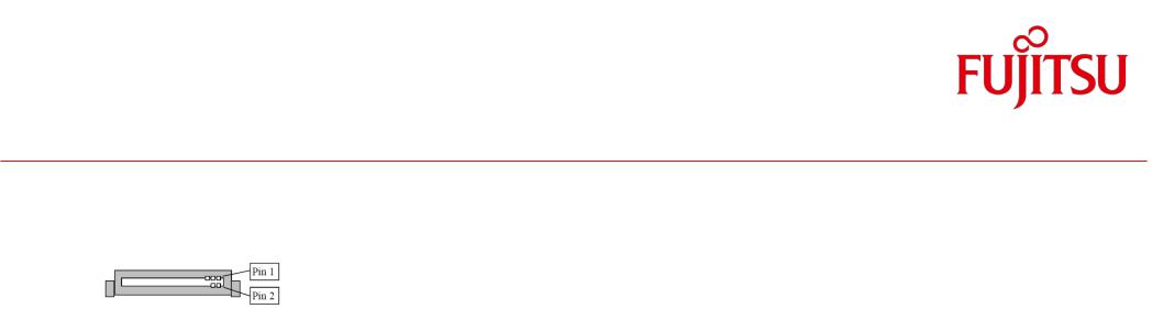
3.14 Serial ATA Connector
|
Pin |
|
Signal |
|
|
Pin |
|
Signal |
|
|
|
|
|
|
|
|
|
|
|
|
|
||||
|
|
|
|
|
|
|
|
|
|
|
|
|
1 |
|
GND |
|
2 |
|
Transmit data positive |
|
|
|
|||
|
|
|
|
|
|
|||||||
|
|
|
|
|
|
|||||||
|
|
|
|
|
|
|||||||
|
|
|
|
|
|
|||||||
|
|
|
|
|
|
|
|
|
|
|
|
|
3 |
|
Transmit data negative |
|
4 |
|
GND |
|
|
|
|||
|
|
|
|
|
|
|||||||
|
|
|
|
|
|
|||||||
|
|
|
|
|
|
|||||||
|
|
|
|
|
|
|
|
|
|
|
|
|
5 |
|
Receive data negative |
|
6 |
|
Receive data positive |
1 |
|
|
|||
|
|
|
|
|
||||||||
|
|
|
|
|
||||||||
|
|
|
|
|
||||||||
7 |
|
GND |
|
|
|
|
|
|
|
|||
|
|
|
|
|
|
|
|
|
||||
TechNotes |
D343x-S V0.2 |
Page 23 of 88 |
http://www.fujitsu.com/fts/products/computing/pc/accessories/mainboards |
Interfaces & Connectors
3.15mSATA Pinout / Mini-PCIe Pinout – Fullsize
Fullsize socket can be used for mSATA (D3433 only!) or Mini-PCIe (D3433 and D3434) and supports auto
detection mode.
(D3433: Mode also selectable via BIOS Setup)
NC: pin not connected to mainboard RSVD: pin reserved, connected on mainboard
Pin |
|
Signal Assignment |
|
Comment |
|||
|
|
mSATA |
|
|
Mini PCIe |
|
|
1 |
|
NC |
|
WAKE# |
|
||
2 |
|
+3.3V |
|
+3.3V STBY |
|
||
3 |
|
NC |
|
|
|
|
|
4 |
|
GND |
|
|
|
|
|
5 |
|
NC |
|
|
|
|
|
6 |
|
+1.5V |
|
|
|
|
|
7 |
|
NC |
|
|
|
|
|
8 |
|
NC |
|
|
|
|
|
9 |
|
GND |
|
|
|
|
|
10 |
|
NC |
|
|
|
|
|
11 |
|
RSVD |
|
REFCLK- |
|
||
12 |
|
NC |
|
|
|
|
|
13 |
|
RSVD |
REFCLK+ |
|
|||
14 |
|
NC |
|
|
|
|
|
15 |
|
GND |
|
|
|
|
|
16 |
|
RSVD |
|
|
|
|
|
17 |
|
NC |
|
|
|
|
|
18 |
|
GND |
|
|
|
|
|
19 |
|
NC |
|
|
|
|
|
20 |
|
EN_WLAN |
|
|
|
for PCIe miniCard |
|
21 |
|
GND |
|
|
|
|
|
22 |
|
NC |
PERST# |
|
|||
23 |
|
SATA TX+ |
PCIe TX+ |
|
|||
24 |
|
+3.3V |
+3.3V STBY |
|
|||
25 |
|
SATA TX- |
PCIe TX- |
|
|||
26 |
|
GND |
|
|
|
|
|
Pin |
|
Signal Assignment |
|
Comment |
|||
|
|
mSATA |
|
|
Mini PCIe |
|
|
27 |
|
GND |
|
|
|
|
|
28 |
|
+1.5V |
|
|
|
|
|
29 |
|
GND |
|
|
|
|
|
30 |
|
NC |
|
|
|
|
|
31 |
|
SATA RX- |
|
PCIe RX- |
|
||
32 |
|
NC |
|
|
|
|
|
33 |
|
SATA RX+ |
|
PCIe RX+ |
|
||
34 |
|
GND |
|
|
|
|
|
35 |
|
GND |
|
|
|
|
|
36 |
|
USB Data negative |
selectable by BIOS |
||||
37 |
|
GND |
|
|
|
|
|
38 |
|
USB Data positive |
selectable by BIOS |
||||
39 |
|
+3.3V |
|
+3.3V STBY |
|
||
40 |
|
GND |
|
|
|
|
|
41 |
|
+3.3V |
|
+3.3V STBY |
|
||
42 |
|
NC |
|
|
|
|
|
43 |
|
GND |
|
|
|
|
|
44 |
|
NC |
|
|
|
|
|
45 |
|
NC |
|
|
|
|
|
46 |
|
NC |
|
|
|
|
|
47 |
|
NC |
|
|
|
|
|
48 |
|
+1.5V |
|
|
|
|
|
49 |
|
NC |
|
|
|
|
|
50 |
|
GND |
|
|
|
|
|
51 |
|
MSATA Present low |
|
||||
52 |
|
+3.3V |
|
+3.3V STBY |
|
||
TechNotes |
D343x-S V0.2 |
Page 24 of 88 |
http://www.fujitsu.com/fts/products/computing/pc/accessories/mainboards |
fInterfaces & Connectors
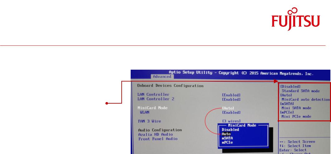
3.16 mSATA / Mini-PCIe BIOS Setup Options
Mini-PCIe Card Mode (only for D3433-S):
The Halsize / Fullsize socket always supports Mini-PCI Express, mSATA and USB 2.0.
The socket can be configured as:
-Standard SATA mode - [Disabled]
-MiniCard auto detection – [Auto]
-Mini SATA mode – [mSATA]
-Mini PCIe mode – [mPCIe]
(BIOS Setup option; default = auto).
Note: BIOS Setup option “WLAN” (for D3433-S and D3434)
This option can be used to enable/disable Mini-PCIe WLAN modules. (BIOS Setup option; default = Enabled).
TechNotes |
D343x-S V0.2 |
Page 25 of 88 |
http://www.fujitsu.com/fts/products/computing/pc/accessories/mainboards |
Interfaces & Connectors
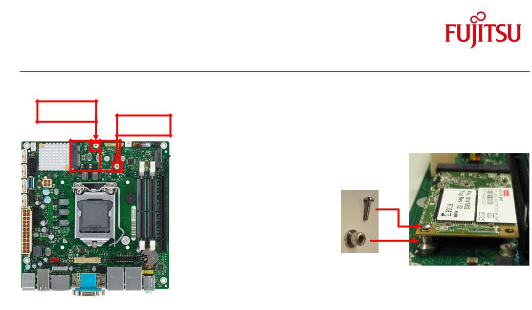
3.17 m-SATA / Mini-PCIe Socket Assembly Note
Solder nut for
Halfsize Minicard
Solder nut for
Fullsize Minicard
Module Assembly Kit (included in mainboard shipment) contains 1metal spacers and 1 mounting screws.
Mandatory torque for mounting screws: 0.25Nm +/- 0.05Nm
Max. torque must never be exceeded, otherwise the mainboard (solder nuts) may be damaged.
Note: Damaged solder nuts are not covered by any warranty!
(mounting screw)
(spacer)
TechNotes |
D343x-S V0.2 |
Page 26 of 88 |
http://www.fujitsu.com/fts/products/computing/pc/accessories/mainboards |

Interfaces & Connectors
3.18 M.2 (Key M) – 2242 & 2260
D3433-S: M.2 cards with SATA or PCIe are supported. PCIe is connected via 2lanes. D3434-S: M.2 SATA only supported.
TechNotes D343x-S V0.2
 Loading...